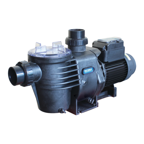
Evolution Evoflow TUF User manual

EVOFLOW
POOL AND SPA PUMPS
Installation and Operation Manual for
EVOFLOW POOL AND SPA PUMPS
TUF | TUF ECO-V | STREAM
This equipment must be installed and serviced by a qualied technician. Improper installation can create electrical
hazards which could result in property damage, serious injury or death. Improper installation will void the warranty.
This manual contains important information about the installation, operation and safe use of this product. Once
the product has been installed this manual must be given to the owner/operator of this equipment.

1.0 FOREWORD
1.1 Congratulations on your recent purchase of an Evolution Evoflow Pump. Please take a
moment to read through the entire manual before using the pump. The pump must be
installed and operated as specified.
2.0 ELECTRICAL SAFETY NOTICE
2.1 The electrical installation is to be done by a licensed electrician.
2.2 Each pump requires a circuit breaker to separate the pump from the electrical supply.
2.3 The contact separation has to provide full disconnection in all poles under over voltage
category III conditions.
2.4 If the pump is to be installed on a swimming pool or pond situation it is mandatory that
an earth leakage circuit breaker with a rated tripping current not exceeding 30mA be
installed.
2.5 Check the pumps nameplate for the following: Voltage, Amp draw and Cycle.
2.6 The power cord, including the ground wire shall have a qualityof 60245 IEC 66 (H07RN-F)
for models greater than 1kW power input.
2.7 For models less than 1kW input the quality shall be of 60245 IEC 57 (H05RN-F).
2.8 All installations must comply with local codes, based on IEC 60364-7-702 requirements.
3.0 ELECTRICAL CONNECTION
3.1 Check that the information on the nameplate corresponds to the power supply.
3.2 Employ a competent electrician to ensure wiring installation is made in accordance with
any local/national rules in the country where the pump is installed. The national wiring
rules in Australia & New Zealand is AS/NZS 3000.
3.3 Install and set the safety devices according to the current stated in the nameplate.
3.4 Single phase motors have a built in thermal overload switch.

1
4.0 SAFETY
4.1 The equipment mentioned in the manual is specially designed for the filtering and
recirculation of water in swimming pools.
4.2 They are designed to work with clean water at temperatures not exceeding 45°C (113°F).
4.3 The user should make sure that assembly and maintenance tasks are carried out
by qualified authorised persons and that these persons have first carefully read the
instructions for service and installation.
4.4 The installation should be carried out in accordance to the safety instructions of
swimming pools, especially Standard HD 60364-7-702, and the specific instructions for
each facility.
4.5 Follow any general safety rules or guidelines and any safety legislation and directives
given by local, state or national authorities.
4.6 Any modification of the pump requires the prior consent of the manufacturer. Original
replacement parts and accessories authorised by the manufacturer ensure a high
level of safety. The manufacturer of the pump assumes no liability for the damage and
injuries caused by unauthorised replacement parts and accessories.
4.7 During operation, some parts of the pump are subject to dangerous electric voltage.
Work may only be performed on the pump or on the equipment connected to it after
disconnection from power sources and after disconnecting the starting device.
4.8 The operating safety of the pump is only guaranteed if the installation and service
instructions are correctly followed.
4.9 The limit values stated in the technical table should not be exceeded under any
condition.
4.10 In the event of defective operation or fault, contact the manufacturer’s technical
support department or its nearest authorised agents.
4.11 If the supply cord is damaged, it must be replaced by an authorised service agent.
4.12 This appliance is not intended for use by children or persons with reduced physical,
sensory or mental capabilities or lack of experience and knowledge unless they have
been given supervision or instruction concerning the use of the appliance by a person
responsible for their safety.

2
5.0 GENERAL INSTALLATION
5.1 The pump must be located as close as practical to the pool. The pump must also be in a
position that enables easy access for periodic servicing.
5.2 Care must also be taken to position the pump in an area that is free from flooding in a
well-ventilated and dry location.
5.3 The pump motor cooling fan must have a minimum clearance of 150mm (6”).
5.4 The pump suction line should be not smaller than 40mm (1.5”).
5.5 The suction line is to have as few bends or elbows as possible. There must not be an air
trap on the suction line.
5.6 Use only the pump barrel unions supplied with the pump.
5.7 Ensure the pump is securely fastened to a level surface in the required position to
prevent movement.
5.8 The pump electrical cable must be wired for the proper voltage and rotation in
accordance with the wiring instructions.
5.9 All wiring and electrical work must be carried out by licensed electricians and installed
in accordance with applicable local codes.
5.10 The motor must be grounded.
5.11 The weight of the plumbing and fittings is to be independently supported and not
carried by the pump.

3
6.0 PRIMING
6.1 The pump will prime and reprime providing the hair and lint pot bowl is full of water and
there is sufficient supply from the suction point.
6.2 If you lose water from the hair and lint pot bowl, it will be necessary to refill it before
starting.
6.3 Remove the clear lid and fill the hair and lint pot bowl with water. Replace the lid,
ensuring the o-ring is correctly located.
6.4 Ensure all suction and discharge valves are open before you start the pump. Operating
the pump with these valves shut can damage the pump.
6.5 Start the pump.
6.6 Allow a few minutes (maximum) for the pump to start delivering water.
6.7 iWARNING: High suction lift or long suction lines will require additional time to prime
and can severely affect the performance of the pump. If the pump will not prime or
produce flowing water, repeat the steps above.
6.8 iWARNING: If allowed to run dry, mechanical seals can be damaged rapidly and may
need to be replaced.
6.9 Ensure that there is always adequate water in the hair and lint pot bowl before starting
the pump.
6.10 If you are unable to prime the pump see 8.0 Troubleshooting.

4
7.0 MAINTENANCE
7.1 The hair and lint pot should be inspected and cleaned at regular intervals.The procedure
for inspection and cleaning is as follows:
1. Remove the lid and lift out the hair and lint pot.
2. Remove debris and hose off with clean water if necessary.
3. Inspect the lid gasket, lubricate with silicon-based grease only if needed. If it is
damaged, replace.
4. Replace the hair and lint pot.
5. Reprime the hair and lint pot bowl.
6. Correctly locate the o-ring.
7. Replace the lid, hand tight only.
8. Switch on pump.
7.2 In climates where the pump may be exposed to frost or freezing, care must be taken
to ensure the pump is protected from damage. It is recommended that if the pump is
not used during this winter period, it should be drained completely. Drain plugs can be
supplied for this purpose. The winterising procedure is as follows:
1. Drain the pump.
2. Do not replace the drain plug. Store it in a safe place until you require the use of the
pump. An example would be within the hair and lint pot bowl basket.
3. If possible, remove the pump and store it in a dry location during this period.
4. When you reactivate the pump, ensure all seals and o-rings are in operational
condition and replace them if necessary—Regrease o-rings and gaskets with silicon-
based grease on refitting.
5. Check that the motor shaft moves freely before reactivation.
6. Reprime pump as per 6.0 Priming.

5
8.0 TROUBLESHOOTING
Fault/Problem Possible Cause Remedy
Pump will not
prime
Suction air leak.
Make sure water level is correct through suction points.
Ensure baskets and strainers are free of debris. Tighten all
ttings/unions on the suction side of the pump, remove and
replace mechanical seal.
No water in the pump. Make sure hair and lint pot is full of water.
Closed valves or blocked
lines.
Open all valves in system, clean skimmer and pump basket,
check pump impeller for blockage.
Motor will not run
No power to motor.
Check that all electrical switches are on. Ensure the circuit
breakers are properly set. Check if timer is set properly. Check
motor wiring at terminals.
Pump jammed. With power switched o, turn pump shaft (should spin freely).
If not contact electrician or Evolution for service.
Low ow
Dirty lter. Backwash lter or clean/replace cartridge lter element.
Dirty skimmer and pump
strainer. Clean skimmer and pump strainer.
Suction air leak. Refer to Pump will not prime.
Closed valve or blocked
line. Refer to Pump will not prime.
Motor runs hot
Be aware some heat from motors is normal. Do not touch hot motors. Thermal overload
protector will deactivate pump if there is an overload or high temperature problem.
Low or incorrect voltage. Supply to be corrected by electrician.
Cooling fan clearance. The pump motor cooling fan must have a minimum clearance
of 150mm.
Installed in direct
sunlight. Shield from the weather.
Poor ventilation. Do not tightly cover or enclose motor.
Noisy pump
operation
Bad bearing. Have electrician replace.
Air leak in suction. Refer to Pump will not prime.
Suction blockage. Locate and clear blockage.
Foreign matter in
impeller.
Dismantle pump and remove foreign matter and debris
from around impeller.
Cavitations.
Improve suction, reduce suction lift, reduce number of
ttings, increase pipe size, increase discharge pressure
and reduce ow by throttling discharge valve
Motor overload
cut outs
Motor not connected
properly. Have electrician check wiring.
Low incoming voltage. Have electrician check voltage, ensure pump is not running on
an extension cord. Report low supply to authorities.
Overload due to binding
in pump or wrong size
impeller.
Contact Evolution for service.

Evolution Water and Lighting Solutions
1/33 Hinkler Drive, Highland Park QLD 4211, Australia +61 7 5565 0000
Unless otherwise indicated, copyright in the content of this document is the property of Evolution Water and
Lighting Solutions under Australian copyright law. Unless otherwise indicated, content may not be reproduced
or transmitted without our prior written permission.
(W99188EV) 09/2022
© 2022 Evolution Water and Lighting Solutions. All rights reserved.
This manual suits for next models
2
Table of contents
Other Evolution Swimming Pool Pump manuals
Popular Swimming Pool Pump manuals by other brands

Viron
Viron P280 eVo Installation and operating instructions

Hayward
Hayward TriStar owner's manual

Hidrotermal
Hidrotermal HIDRO-BPS050 user manual

Pentair Pool Products
Pentair Pool Products SuperFlo Installation and user guide

Aqua
Aqua Simpool Timer instruction manual

atecpool
atecpool ATECF11 Installation Guide and User Manaul