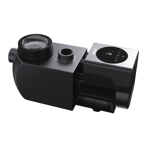
CLS VICTORIA PLUS SILENT User manual

VICTORIA PLUS SILENT MANUAL
VICTORIA PLUS SILENT
SWIMMING POOL PUMPS

Installation and general maintenance manual - POOL PUMPS 3
ENGLISH
IMPORTANT
Thismanualcontainsbasicinformationonthesafetymeasurestobe adopted during installation and start-up.
Thetterandthe user must thereforereadthe instructions before installationandstart-up.
Themanualcan bedownloadedas a PDF le from thewebsite:www.astralpool.com
1. GENERAL SAFETY INSTRUCTIONS
These symbols ( ) indicate the possibility of danger where the corresponding instructions
are not followed.
DANGER.Risk of electrocution.
Failuretoabide by theseinstructionsmayleadtothe risk ofelectrocution.
DANGER.
Failuretoabidebytheseinstructionsmayleadtotheriskofinjurytopeople ordamageto property.
WARNING.
Failuretoabidebytheseinstructionsmayleadtotheriskofdamagetothepumportheinstallation.
2. GENERAL SAFETY REGULATIONS
GENERAL
-The units described in this Manual are specially designed for the pre-ltering and recirculation of
water in swimming pools.
-They are designed to work with clean water at temperatures that do not exceed 35 ºC.
-Install them in line with the specic instructions for each installation.
-Respect current regulations regarding accident prevention.
-All modifications to the pump require prior authorization from the manufacturer. Original spare parts
and accessories authorized by the manufacturer ensure greater safety. The pump manufacturer is
exemptfrom allliability regarding anydamagecausedbyunauthorized spare parts or accessories.
-When working on each unit or others connected to them, disconnect the unit from the power
supply and the start-up devices, as the electrical parts of the pump are live during operation.
-All assembly and maintenance work must be carried out by qualied, authorized personnel who
havecarefullyreadthe installation and service instructions.
-To guarantee safety when operating the machine, you must comply with the installation and
service instructions.
-Inthe eventof defective operationor faults, contact your supplier or nearest dealer.

Installation and general maintenance manual - POOL PUMPS
4
ENGLISH
WARNINGS DURING INSTALLATION AND ASSEMBLY WORK
-In cases of junction box connections only: when connecting the electrical wiring to the mo-
tor, check the layout inside the connection box and make sure there are no pieces of wiring
inside after it has been closed and that the earthing conductor is correctly connected. Con-
nect the motor in line with the wiring diagram attached to the machine.
-In cases of junction box connections only: make sure that the electrical wiring connections
to the terminal box are well mounted and screwed tightly to the connection terminals.
-The unit should be connected to an alternating current supply (see data on the pump’s
plate) with an earth connection, protected by a residual current device (RCD) with a rated
residual operating current that does not exceed 30 mA.
-Ensure the seal of the motor’s junction box is properly tted to prevent water getting in.
Likewise, position and tighten the gland inside the cable duct of the junction box.
- Make sure that water is unable to enter the motor or the live electrical parts.
-Wheretheintendeduseisnotasindicated,additionaltechnicaladaptationsand regulations
may apply.
WARNINGS DURING START-UP
-Before starting the machine, check the calibration of the electric protection devices on the mo-
tor and that the protection against electrical and mechanical contacts is correctly positioned and
secure.
NOTE
The pool should not be used while the pump unit is running.
Do not use the pump if anyone is in contact with water.
WARNINGS DURING ASSEMBLY AND MAINTENANCE WORK
-Follow local installation regulations when assembling and installing the pumps.
-Make sure that water is unable to enter the motor or the live electrical parts.
-Avoid contact at all times - even accidentally - with moving parts while the unit is running and/or
before it comes to a complete standstill.
-Wait for the unit to come to a halt before handling it.
-Before any electrical or mechanical maintenance operation, disconnect the unit from the power
supply and block the start-up devices.

Installation and general maintenance manual - POOL PUMPS 5
ENGLISH
-Follow the steps below before handling the unit:
1. Disconnect the unit from the mains.
2. Block all start-up devices.
3. Check thatthere is no voltagein the circuits, even inthe auxiliarycircuits and additional features.
4. Wait for the impeller to come to a complete standstill.
The above list is a guideline only as there may be other requirements in addition to local laws for safety
reasons.
-For regular control:
Check that the mechanical parts are tightly secured and check the condition of the screws sup-
porting the machine.
Check that the power conductors and isolating parts are in their correct position, are secure and
in a good state of repair.
Check the temperature of the machine and the electric motor. In the event of a fault, stop the
machine immediately and contact the nearest Technical Assistance Service.
Check formachinevibrations. Inthe eventof afault, stopthe machine immediately andcontact
the nearest Technical Assistance Service.
-Due to the complex nature of the cases described, the installation, user and maintenance instruc-
tions contained in this manual do not seek to examine all possible and imaginable cases of service
and maintenance. Should you require additional instructions or have specic problems, please do
not hesitate to contact the nearest Technical Assistance Service.
The electrical installation should be done by someone qualied in working with electrical equipment. This
unit is not designed for those with a physical, sensory or mental handicap or people lacking in experience,
unless done under supervision or with instructions of use from a person in charge of safety.
Do notpermitchildren noradults tosit or lean onthe unit.Childrenshouldbe supervised toensurethat they
do not play with the unit.
This appliance can be used by children aged from 8 years and above and persons with a reduced physical,
sensory, or mental handicap or lack of experience and expertise if they are supervised or have been given
instructions on the safe use of the appliance and understand the hazards involved.
Cleaning and user maintenance must not be done by children without supervision.

Installation and general maintenance manual - POOL PUMPS
6
ENGLISH
3. INSTALLATION AND ASSEMBLY
GENERAL
-Our pumps may only be assembled and installed in pools or ponds that are compliant with stan-
dard HD 384.7.702. Should you have any doubts, please consult your dealer.
-The installation should follow standard IEC 60364-7-702 for swimming pools.
-The pump can be installed in zones 1 or 2.
-Fit the pump horizontally in order to accommodate the pre-lter. The pumps are tted with a
pre-lter with a basket inside to collect any large particles, as they may damage the hydraulic
parts inside the pump.
-All pumps are tted with a stand with holes in it to anchor it to the ground (Fig. 1).
PIPING
-To connect the piping, glue the pipes and the connectors, supplied together with the pump; the
tting connections to the suction and return ports on the pump are threaded and include seals to
prevent water loss (Fig. 2).
-Fit thereturnpipes completely perpendicularandcenteredin relation tothe portto beconnected
to prevent the pump and the pipe from being subjected to external stress, which apart from ma-
king tting dicult, could break them (Fig. 2).
-Fit thesuctionpiping ona slight2% slopetowards thepump to avoid theformationof airpockets
(Fig. 2).
-To ensure the pump works correctly, prime the pump pre-lter until water rises up through
the suction pipe (Fig. 3).
LOCATION
-Fit the pump below the water level in the pool to improve pump performance.
-If a self-priming pump is to be tted above the water level, the pressure dierential to the pump
suction pipe should not be higher than0.02 MPa (2mH2O). Ensure thatthe suction pipe isas short
as possible as a longer pipe would increase suction time and the installation’s load losses.
-Make sure that the pump is safe from possible ooding and receives dry ventilation.

Installation and general maintenance manual - POOL PUMPS 7
ENGLISH
ELECTRICAL INSTALLATION
-It is essential that you use a multiple disconnection device with a space of at least 3 mm between
surfaces to disconnect the unit from the electrical current.
-Use a rigid cable to connect the pump to the mains. If you use a exible cable to connect it to the
mains, it must have cable lugs to connect it to the terminals of the pump’s motor.
-The unit shouldbe connected toan alternatingcurrentsupply (seedata on thepump’s plate) with
an earth connection, protected by a residual current device (RCD) with a rated residual operating
current that does not exceed 30 mA.
-Adjust the value of the ground fault circuit interrupter in line with pump intensity.
-Before connecting the motor, check the type of fuse required.
-Check the layout and connection of the earthing cable in the unit.
-Respect the electrical installation and connection instructions. Failure to do so may lead to the
pump’s manufacturer declining all liability and rendering the warranty null and void.
-The installation may be subject to special regulations.
-Unsuitable mains connections involve the risk of electrocution.
For pumps with a single-phase motor:
• Thermal protection is incorporated.
• Use a motor guard with magneto-thermal protection.
• The adjustment data for the thermal relay is to be used as a guideline, as the motor is already
tted with protection.
• For 230 V, use a H07 RN-F3 type connection sleeve with a cable section that adapts to the power
of the motor and to the length of the cable.
For pumps with o three-phase motor:
• Use a motor guard with magneto-thermal protection.
• Protect the pump against overloads with a cut-o switch for the motor.
• Adjust the thermal value according to the thermal protection table. For the connection Δ
(3 x 230 V network), use the protection with the highest indicated value. For the connec-
tion Υ (3 x 400 V network), use the protection with the lowest indicated value.
• Connect the lowest voltage at Δ and the highest at Υ for voltage intervals other than 230/400 V;
400/690 V.
• For AC, use a H07 RN-F3 type connection sleeve with a cable section that adapts to the power of
the motor and the length of the cable.
• The mains cable may only be connected by skilled, authorised personnel.
Installation and general maintenance manual - POOL PUMPS
8
ENGLISH
4. START-UP INSTRUCTIONS
PRIOR TO START-UP
- Measurements prior to rst start-up:
1. Remove the pre-lter cap by unscrewing the nut holding it in place (Fig. 5).
2. Fill the pump with water through the pre-lter until it rises up through the suction pipe.
3. Should the basket be removed during these operations, do not forget to replace it to
prevent large particles from entering the pump that could block it.
4. Check that the mains voltage and frequency correspond with those indicated on the
pump’s rating plate.
-Fit the pre-lter cap and screw on tightly, without forgetting to t the seal in its housing (Fig. 5).
-The pumps must not be run without the pre-lter having rst been lled with water. Where
this is not the case, the mechanical gasket may be damaged, leading to a loss of water.
-Check that the motor rotates in the correct direction by means of the fan located at the back
of the motor that can be seen through the view hole on the fan cover (Fig. 6).
START-UP
- Open all the valves and connect the motor.
- Activate the self-priming mode and wait a reasonable time for this to be completed.
5. MAINTENANCE
Depending on the level of water cleanliness, the following should be done every 100 operating hours:
-Clean the pre-lter basket regularly to avoid drops in pressure. To prevent the basket from brea-
king, do not hit it during the cleaning process.
-Should the pump stop, check that the consumption in amperes of the motor that is running is
equalto or below that indicatedon the manufacturer’srating plate.Ifthis informationis notavai-
lable, contact the nearest Technical Assistance Service.
-Empty the pump if it is to remain at a standstill for a certain length of time, especially in cold
countries where there is a risk of freezing.
-Remove the purge cap to empty the pump.
-Every time the pre-lter is opened, clean the seal and its housing of any impurities to ensure air-
tightness when the cap is closed (Fig. 5).

Installation and general maintenance manual - POOL PUMPS 9
ENGLISH
-Pump components that, due to their normal use, suer wear and/or tear must be regularly repla-
ced to ensuregood pumpperformance.The followingtableliststhe fungible and/ orconsumable
components of the pump and the period of time in which they must have been replaced.
DESCRIPTION OF THE COMPONENT TIME BETWEEN REPLACEMENTS
Condenser 10,000 h
Bearings 10,000h
Mechanical seal 10,000h
O-rings and other sealing components (1) 10,000h
(1) The opening and closing of the pump for the replacement of any of the inner spare parts does not
guarantee the subsequent sealing. For this reason, it is recommended that the O-rings and sealing
components are replaced whenever the mechanical seal and / or bearings are changed.
The estimated working life of the above parts has been established according to normal product use and
installation conditions.
Follow the instructions in the installation manual to maintain the working life of the pump.
6. REMOVAL
-The motor unit can be removed from the pump body without having to disconnect the pump’s
suction and return pipes.
-To remove the motor unit from the pump body, remove the screws that join them together.

Installation and general maintenance manual - POOL PUMPS
10
ENGLISH
7. TROUBLESHOOTING
1. The pump is not primed 4. The pump will not start
2. The pump only releases a small ow of water 5. The motor is making a noise but will not start
3. The pump makes a noise 6. The motor has stopped
123456 CAUSES SOLUTIONS
Air entering the suction pipe Check the condition of connections
and seals on the suction pipe
Filter cap badly sealed Clean the lter cap and check the
condition of the rubber seal
Motor turning in wrong direction Invert 2 power phases
Wrong voltage Check the voltage on the rating plate
and that of the mains
Pre-lter blocked Clean the lter
Load loss in the installation Prevent parts from causing load loss
wherever possible
Pump incorrectly secured Secure the pump correctly
Motor blocked Remove the motor and contact the
technical service
Increased temperature in the terminal
box due to electric arc
Check the junction box connections
The thermal protection trips Connect the cables correctly to the
junction boxes
Incorrect junction box connections Tighten the cable correctly to the
junction box / Adapt the size of the
cable connection to the junction box

59MT
Anchor detail
ANCHOR DETAIL
CORRECT INCORRECT
Fig. 1
Fig. 2
Gasket / Joint Gasket / Joint
Union
Union
Union
Union

6160
Fig. 3
Fig. 4
Priming
Pump
Max. 2 m

6160
Fig. 5
Fig. 6
Pre-lter cover nut
Pre-lter cover
Seatin joint to be cleaned Tower joint
Pre-lter
Basket
Fan Cover
CORRECT INCORRECT

MT62
Condensor
SINGLE PHASE MOTORS
THREE PHASE MOTORS
SINGLE PHASE THREE PHASE
Fig. 6

Installation and general maintenance manual - POOL PUMPS 63
ENGLISH
GUARANTEE CERTIFICATE
1. GENERAL TERMS
1.1. In accordance with this provisions, the seller guarantees that the Astral Product corresponding to this guarantee ( “The Product”)
doesn’t have any default in conformity at this time of delivery.
1.2. The guarantee term for the product is three (3) years and will be calculate from the date of delivery to the purchaser .
1.3. In the event of any default in conformity of the product and the purchaser noties the seller of such default during the guarantee
period, the seller is obliged to repair o replace the Product at its own cost in the place that he consider convenient, unless it is
impossible or disproportionate.
1.4. When it is not possible to repair or replace , the purchaser may request a proportional reduction in the price, or, if the default in
conformity is sucient signicant , the termination of the contract.
1.5. The parts replaced or repaired under this guarantee will not extend the guarantee term of the Product, although will have their
own guarantee.
1.6. In order for this guarantee to come into eect, the purchaser must prove the date of acquisition and delivery of the Product.
1.7. If after six months from the delivery of the Product to the purchaser , a default of the conformity of the product is notied, the
purchaser must prove the origin and existence of said defect.
1.8. This Guarantee Certicate does not limit or prejudge the rights corresponding to the consumers by virtue of national compulsory
standards.
2. INDIVIDUAL TERMS
2.1. This Guarantee covers the following AstralPool products and product ranges: “Victoria Plus Silent”.
2.2. This Guarantee Certicate will be applicable exclusively in countries of the European Union.
2.3. In order for this guarantee to be eective the purchaser must strictly follow the manufacturer’s instructions included in the docu-
mentation accompanying the Product, if said documentation is applicable depending on the range and model of the Product.
2.4. When a schedule is given to replace, maintain or clean certain parts or components of the Product, the guarantee will only be valid
if this schedule has been followed correctly.
3. LIMITATIONS
3.1. This guarantee will apply exclusively to sales made to consumers. A “consumer”, is understood to be the person who acquires the
Product for purposes not connected with his professional activity.
3.2. No guarantee is given for the normal wear through using the product. With regard to parts, components and/or expendable equip-
ment such as mechanical seals, bearings and water tightness, the documentation accompanying the product will be applicable, as
the case may be.
3.3. The guarantee does not cover accessory elements of the product “Victoria Plus Silent” not explicitly included on it, such as panel
board, converter, protection devices, etc.
3.4. The guarantee covers Product’s failures originated only and exclusively by materials defect and/or performance works. The guarantee
doesn’t cover cases such us the Product: (I) has been object of an incorrect handling; (II) has been installed, repaired, maintained or
manipulated for an non-authorized person or (III) has been repaired or maintained with non original spares. It’s out of the present
guarantee the slight damages originated by accidental tears or inadequate as:
• Pump working without water
• Incorrect dosication of chemical products on the swimming pool
• Water damage originate in external elements to the pumping conditions.
• Inadequate ventilation
• Use in dierent applications of swimming pool water ltration.
3.5. The guarantee does not cover cases of incorrect installation or start-up unless said installation or start-up is included in the sales
contract of the Product and has performed by the seller or under his responsibility. This cases are covered by the installer or the
seller who installed the product.

ASTRAL VICTORIA PLUS SILENT PUMP SPECIFICATIONS - PRODUCT AND ACCESSORIES DESCRIPTION
The body of the pump is made of the latest generation thermoplastics. The pumps are self-priming and range from 0.50 HP up
to 3 HP, and are provided with both single-phase and three-phase motors. A pre-lter has been integrated into the body of the
pump to prevent the entry of any foreign bodies which could cause damage to the hydraulic parts of the pump.
The motors supplied with the motor pump unit have been protected with IP-55 protection and are adapted to withstand hot
atmospheres and high humidity levels.
ENGLISH


TECHNICAL CHARACTERISTICS
CODE
MOTOR H
max.
(m)
NOISE DIMENSIONS (mm) PVC
PIPE
D.HP
P1
Kw
VOLTAGE
(V) dB A B C De Di E F G H I
65557
½0,58 230
C.71
13
61
581 281 246 ACME D.75 2" GAS 359 322 321 164 254
50
65558 0,55 230 - 400 581 281 246 ACME D.75 2" GAS 359 322 321 164 254
65560
¾0,65 230 14 581 281 246 ACME D.75 2" GAS 359 322 321 164 254
65561 0,82 230 - 400 581 281 246 ACME D.75 2" GAS 359 322 321 164 254
65562
10,98 230 17 581 281 246 ACME D.75 2" GAS 359 322 321 164 254
65563 1,02 230 - 400 581 281 246 ACME D.75 2" GAS 359 322 321 164 254
65564
1 ½ 1,46 230
C.80
18
66
615 281 246 ACME D.75 2" GAS 359 356 321 164 254
63
65565 1,4 230 - 400 615 281 246 ACME D.75 2" GAS 359 356 321 164 254
65566
21,85 230 18 615 281 246 ACME D.75 2" GAS 359 356 321 164 254
65567 1,91 230 - 400 615 281 246 ACME D.75 2" GAS 359 356 321 164 254
65569
32,56 230 C.90 22,5 646 281 246 ACME D.75 2" GAS 359 387 321 164 254 75
65570 2,4 230 - 400 C.80 615 281 246 ACME D.75 2" GAS 359 356 321 164 254
Cod. 65557-0008 / Rev. 03
−We reserve the right to change all or part of the features of the articles or contents of this document, without prior notice.
Table of contents
Other CLS Swimming Pool Pump manuals
Popular Swimming Pool Pump manuals by other brands

Polygroup
Polygroup SUMMER WAVES ST1100 owner's manual

Gemas
Gemas RANGER instruction manual

Hayward
Hayward Super Pump VS SP2603VSP owner's manual

G&F Manufacturing
G&F Manufacturing 5005001B Install & Operation Manual

UK POOL STORE
UK POOL STORE UKPS16 instructions

OKU Obermaier
OKU Obermaier SPS25 instruction manual

Pentair Pool Products
Pentair Pool Products Sta-Rite CF6EF-81L owner's manual

Wayne
Wayne WAPC250 Operating instructions & parts manual

atecpool
atecpool ATECF11 Installation Guide and User Manaul

Pahlen
Pahlen WaterVISE manual

Astral Pool
Astral Pool VICTORIA DUAL SPEED manual

HydroPro
HydroPro + premium 7 Installation instructions manual