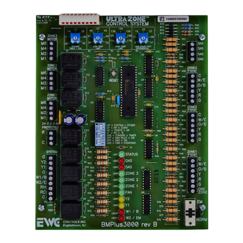
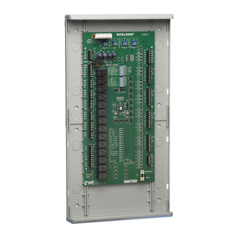
EWC Controls ULTRA-ZONE ULTRA-TALK UT-3000 User manual

©2015GoodmanManufacturingCompany,L.P.
68°
74°
74°
76°
68°
76°
76°
74°
UT‐3000ZoningControl

©2015GoodmanManufacturingCompany,L.P.
ZoneControlFeatures
Installation
ProgrammingandSet‐up
LCDScreens
TroubleshootingandBiasDataVoltages
Agenda

©2015GoodmanManufacturingCompany,L.P.
ZoneControlFeatures
Providesintelligentcontrolof
communicationor24Vlegacy
HVACsystems.
Uptofivezonesusing24V
motorizeddampers.
100%plugandplaywhen
connectedtocommunicating
HVACsystemandnetwork
thermostats.
Modulatingandstaged
operation,autoequipment
recognition,anddualfuel
functions.
Precisecontrolofsupplyair
targetandlimitsetpoints.

©2015GoodmanManufacturingCompany,L.P.
ZoneControlFeatures
Controls2‐3zoneswith24Vacpoweropen/closeorspringassistedmotorized
dampers.
Canbeexpandedtofive(5)zonesbytwinning two(2)UT3000controls
together.(refertoEWCTB‐241forinstructionsontwinning)
ControlsanycommunicatingHVACsystembasedonClimateTalkopenprotocol,
orany:
24V2heat/1coolgas/electricsystem.
24v2heat/1coolconventionalordualfuelheatpump.
ClimateTalk

©2015GoodmanManufacturingCompany,L.P.
ZoneControlFeatures
Theliquidcrystaldisplay
rotatestoshoweach
zonesdemand.
LiquidCrystalDisplay
Theoutsideandsupply
airtemperaturesare
alsodisplayed.
Thedisplaywillshowthethermostatdemandinput,
andtheHVACsystemoutput.

©2015GoodmanManufacturingCompany,L.P.
ZoneControlFeatures
FourbuttonsareprovidedjustbelowtheLCDscreen.
ThebuttonsareusedtoscrollthroughthemenuontheLCDandmake
yourselections.
Also,usedtoprogramtheUT‐3000andselectthefeaturesyoulike.
4ButtonLCDProgramming
Back Forward
SelectUp
SelectDown

©2015GoodmanManufacturingCompany,L.P.
ZoneControlFeatures
SystemLED’sprovidevisual
indicationoftheHVAC
systemstatusandcurrent
modeofoperation.
Atotalofthree(3)green
damper LED’slabeledzone1
throughzone3,indicate
whichdampersare
energizedtoopen.
Zone1=LED12,Zone2=LED
11,andZone3=LED10.
SystemLED’sandDamperLED’s

©2015GoodmanManufacturingCompany,L.P.
ZoneControlFeatures
Atotaloffour(4)green
pulsingLED’sareprovidedto
indicateifacommunication
linkhasbeenestablished
betweeneach
communicatingt‐stat,and
thecommunicatingHVAC
system.
Aseriesofrapid andrandom
pulsesindicateasuccessful
comm‐link anddata
transmission.
(LED’s19,20,21,and22)
CommunicatingLED’s

©2015GoodmanManufacturingCompany,L.P.
ZoneControlFeatures
TheUT‐3000comespre‐
programmedwithdefault
operatingparametersforzoned
HVACsystems.
Thedefaultprogramsettingsfree
thetechnicianfromprogramming,
andallowsfinetuningofthe
systemtooptimizeits
performance.
TheUT‐3000operatesinstaged
andmodulatingmodeatalltimes.
Minimizesblowerspeed,
maximizestemperaturecontrol,
andimprovessystem
performance.
FaultFreeProgramming&IntuitiveTemperatureControl
Table1.FromEWCControlsTechnicalBulletin:TB‐241
Feature Default RangetoSelect
SystemType Heat/Cool HeatPumporHeat/Cool
HPType NONDual Fuel DualFuelorNon‐DualFuel
T‐StatType Heat/Cool HeatPumporHeat/Cool
RevValve RV‘O’ ‘O’TypeRVor‘B’TypeRV
FanMode Gas GASorHYDRO(Electric)
OASSP 15° OFFor7° to42°F
O.T.Offset 15° 5° to20°F
U.T.Offset 8° 5° to10°F
SASHPTGT 100° 90° to120°F
SASGasTGT 130° 120° to170°F
SASCoolTGT 50° 42° to60°F
SASRSPDLY 30s 10s– 180s
W2Threshold 80% 65‐100%
(Adj.in5pointincrements)
PURGEFAN 25% 25‐100%
(Adj. in25pointincrements)
LegacyDMD 50% 25%,50%,75%,or100%
TotalZones 3 2or3zones
LimitSASPID N YesorNo

©2015GoodmanManufacturingCompany,L.P.
ZoneControlFeatures
TheUT‐3000controlboard
includesaSPDTindoorair
quality(IAQ)dryrelay.
Thisrelayhasadigitalor
24vinputtriggerthatcan
beusedtointerlockand
controlancillarydevices.
Freshairdamper
Wholehousehumidifier
Wholehouse
dehumidifier(viathe
ComfortNetsystem)
Energyrecoveryventilator
AncillaryIAQDryRelayProvided

©2015GoodmanManufacturingCompany,L.P.
ZoneControlFeatures
Thedryrelayoperationcanbe
utilizedviaaauxiliarycontroller
attachedtotheR,C,andRelay
terminalsinzone1.
Whentheauxiliarycontroller
initiatesthecall,terminalsNO
andConthedryrelaywill
close.
Thisconnectionwill
bringonyourancillary
IAQdevice.
AncillaryIAQDryRelayOperation

©2015GoodmanManufacturingCompany,L.P.
ZoneControlFeatures
AncillaryIAQDryRelayLocationsonUT‐3000

©2015GoodmanManufacturingCompany,L.P.
ZoneControlFeatures
ConfigurationsandTypesofThermostatsUsed
UT‐3000 +Communicating T‐Stats
inallzones
UT‐3000 +(1)CommunicatingT‐stat,
(2) 24vT‐Stats
UT‐3000 +24vT‐statsinallzones

©2015GoodmanManufacturingCompany,L.P.
ZoneControlFeatures
Installation
ProgrammingandSet‐up
LCDScreens
TroubleshootingandBiasDataVoltages
Agenda

©2015GoodmanManufacturingCompany,L.P.
Installation
Chooseasuitablelocationtomount
theUT‐3000housing.
Preferred locationswouldbeareturn
duct,nearbywall,orconvenientstuds
whereplywoodcanbeinstalledto
supportthehousing.
AVOID:Supplyduct,airhandler,
furnacehousing,evaporatorhousing,
orhotwatercoilsofanytype.
Follownationaland/orlocal
electricalcodes.
MountingControlBoard

©2015GoodmanManufacturingCompany,L.P.
Installation
EWCalwaysrecommendsto
installaseparatetransformer
topowertheUT‐3000.
FollowNECand/orlocal
electricalcodes.
PowerandWiring
R
C
InstallaSeparate
Transformer
ToPowertheUT3000
Power
Supply
ToProtected
LineVoltage
OPTIONAL
CondensatePump
SafetyFloatSwitch
ToZone
ControlPanel
FieldSupplied“Dedicated”
ListedTransformer
24vac40vaMin/60vaMax

©2015GoodmanManufacturingCompany,L.P.

©2015GoodmanManufacturingCompany,L.P.
Installation
Whenpossible,trytoadheretotheClimate
Talkcolorcode.(red,green,yellow,white)
However,ifyouusestandard18/4wiring,it
mighthaveslightlydifferentcolors.
Chooseyourcolorcodes,andstickwiththat
samecodethroughoutinstallation.
PowerandWiring
Communicating
OutdoorHeatPump
orCondensingUnit
Communicating
AirHandler
orFurnace
W
Y
G
R
G
RH
RC
C
JMP1
RC/RH
LINK
C
2
1
R
SYSTEM
1
2
R
1
2
R
CWHITE
YELLOW
GREEN
RED
C

©2015GoodmanManufacturingCompany,L.P.
Installation
Standard24vacdampercontrol.(2or3wire)
TerminalPC‐24vacpowertoclose thedamper.
TerminalPO‐24vacpowertoopen adamper.
TerminalC‐24vaccommon.(neutral)
WiringDamperstoBoard‐TerminalBlockDesignation&Function

©2015GoodmanManufacturingCompany,L.P.
Installation
Youcanconnectuptoeighteen (18)genuineND,URD,orSIDdamperstoa
singleterminalblockbeforerelayisolationisrequired.
Youcanonly connectone (1)RSDorcompetitor’sspring typedampertoasingle
terminalblock.
Three setsofdamperwirescanterminate(piggyback)intoone damper
terminal.(twoshownhere)
WiringMultipleDampersIntoOneDamperTerminalontheUT‐3000
Table of contents
Other EWC Controls Controllers manuals
