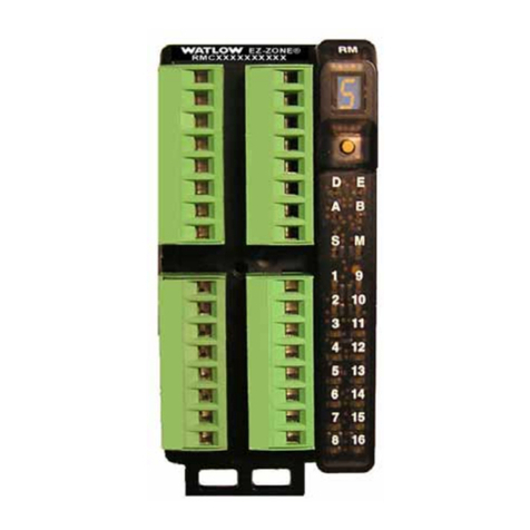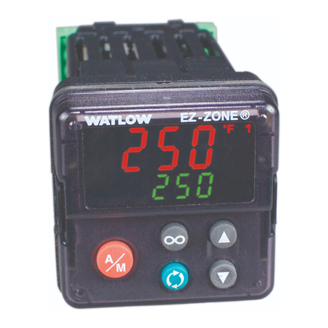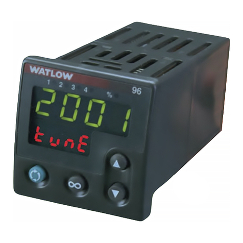
Watlow EZ-ZONE®RM System •4 •Chapter 1 Overview
A Conceptual View of the RM System
The flexibility of the RM’s software and hardware al-
lows a large range of configurations. Acquiring a bet-
ter understanding of the controller’s overall function-
ality and capabilities while at the same time plan-
ning out how the controller can be used will deliver
maximum effectiveness in your application.
The system at a high level can have a total of 17
modules installed, one of which can be an Access
module and the others (16 maximum) can be any
combination of Control or Expansion modules. With
the exception of the Access module, the user will de-
fine each address via the button on the face of each
module. Each installed Control or Expansion module
must have a unique Standard Bus address ranging
from 1-9, A-F, H. The Access module will be delivered
with a default Standard Bus address of 17 (J).
The RMC (Controller) can be ordered with up to
four loops with default loop configurations (all loops)
out of the box as follows:
Analog Input functions set to thermocouple, type•
J
Control loops 1 through 4 use Analog Inputs 1•
through 4 respectively
Heat algorithm set for PID, Cool set to off•
Control mode set to Auto•
Set point set to 75° F•
So, for a heating application, to complete a heating
loop configuration simply configure one or more out-
put functions as Heat Power.
Note:
Zones can communicate with one another over the
backplane (local and split rail). Once the system is
configured and running changing zone addresses
without careful deliberation may cause disruption in
operation.
Some of the user selectable ordering options are
listed below:
1. Class 2 or SELV (Saftey Extra Low Voltage) equiv-
alent Power Supplies:
90-264 Vac to 24Vdc @ 31 watts•
90-264 Vac to 24Vdc @ 60 watts•
90-264 Vac to 24Vdc @ 91 watts•
2. RM Control Module can provide:
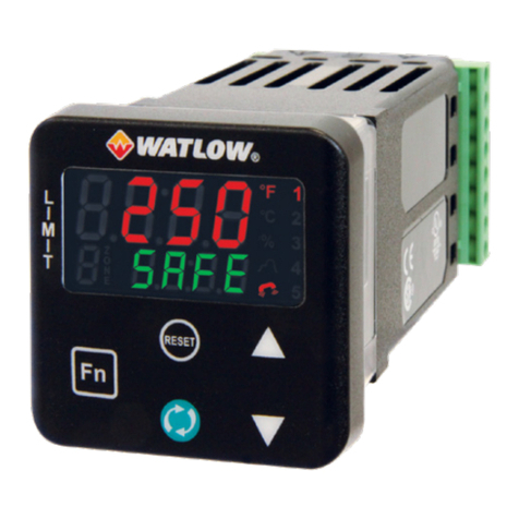
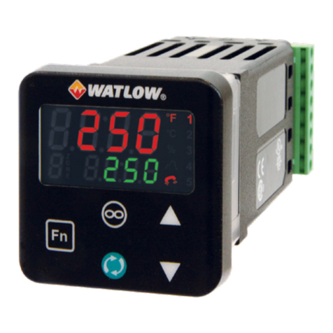
1 to 4 control loops, limits or CT inputs•
1 to 9 inputs (various types)•
1 to 12 outputs (various types)•
Modbus RTU communications•
3. RM Expansion Module can provide:
1 to 24 Digital Inputs/Outputs (I/O)•
4 to 12 Form A Mechanical Relays•
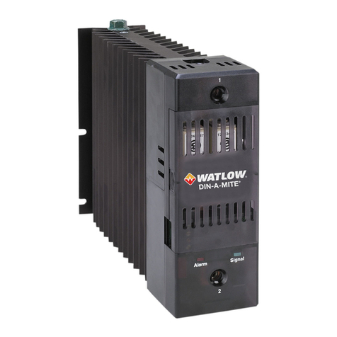
2 to 4 Form A 10A Solid-State Relays•
4 inputs for external Current Transformers•
(CT)
4. RM Access Module can provide:
Communications - DeviceNet, EtherNet/IP,•
Modbus RTU/TCP
Battery Backup•
Real Time Clock•
Data Logging•
Auto-Configuration Backup•
As can be seen above the RM system is fully scalable
with regards to power requirements, number of loops,
inputs, and outputs.
It is useful to think of the controller in three
parts: inputs (analog and digital), functions (math,
logic, PID, etc.), and outputs (relay, SSR, switched
DC, analog and or digital). Information flows from
an input to a function to an output when the control-
ler is properly configured. A single RM controller can
carry out several functions at the same time; for in-
stance: mathematical operations, closed-loop control,
monitoring for several different alarm situations and
operating switched devices, such as lights and mo-
tors. Each process needs to be thought out carefully
and the controller’s inputs, functions and outputs
configured properly.
What is an Instance?
The RM system has lots of features, in most cases
more than one. For example, an RM module can have
four control loops. They are named Control Loop 1,
Control Loop 2, Control Loop 3 and Control Loop 4.
Each is an instance of a control loop. They are num-
bered, 1, 2, 3 or 4 to distinguish between them and
that number indicates the specific instance of a con-
trol loop in the module. These instance numbers are
used when you link inputs, functions and outputs.
For example, when configuring a heat output the
control loop instance (1, 2, 3 or 4) to drive the output
must be defined.
Functions
Functions, in simple terms use input signals (real-
world or internal), to calculate a value and deliver an
output. A function may be as simple as configuring
the function of the analog input, i.e., thermocouple,
RTD, etc., or reading a temperature to set an alarm
state to on or off. Or, in differential control it could be
looking at the difference between two inputs for the
purpose of establishing a new set point value.
To use a function you will typically select the
source of its inputs and set its other options as well.
Some functions have a hardware input for which the
sources are preset and cannot be changed. The Ana-
log Input 1 function's input comes, not surprisingly,
from the sensor attached to the RM's first analog in-
put. Most functions, however, get their inputs from
other function's outputs. For example, the function
Alarm 1, can get its input from a variety of sources
including any of the instances of analog inputs or
current transformers in the controller. To select an
input for a function, you set the function's Source
Function, Source Instance and Source Zone param-
eters. To set Alarm 2 to monitor Analog Input 3
in a module with zone address 8, you set Alarm 2's
Source Function to "Analog Input", Source Instance
to "3" and Source Zone to "8". Most functions can ac-
cept more than one input. The source parameters for
the first input to a function are called Source Func-
