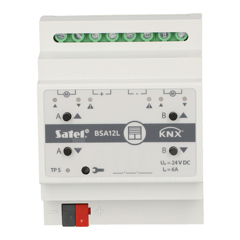
Satel KNX-BSA12H User manual

KNX-BSA12L (24 VDC)
KNX-BSA12H (230 VAC)
Blind/shutter Actuator
Quick installation guide
Full manual is available on www.satel.eu
Firmware version 1.02 knx-bsa_sii_en 11/19
SATEL sp. z o.o. •ul. Budowlanych 66 • 80-298 Gdańsk • POLAND
tel. +48 58 320 94 00
www.satel.eu

IMPORTANT
The device should be installed by qualified personnel.
Prior to installation, please read carefully this manual in order to avoid mistakes that can lead
to malfunction or even damage to the equipment.
Changes, modifications or repairs not authorized by the manufacturer shall void your rights
under the warranty.
SATEL aims to continually improve the quality of its products, which may result in changes in
their technical specifications and software. Current information about the changes being
introduced is available on our website.
Please visit us at:
http://www.satel.eu
The declaration of conformity may be consulted at www.satel.eu/ce
The following symbols may be used in this manual:
- note;
- caution.

This manual only regards the installation of modules KNX-BSA12L and KNX-BSA12H. For
more information about modules and their configuration, please refer to the full manual
available at www.satel.eu.
1. Description
The KNX-BSA12L and KNX-BSA12H are KNX blind/shutter actuators that allow you to
control the movement of sun protection products such as horizontal (Venetian) blinds, vertical
blinds, roller shutters and awnings. They also enable control of the movement of electrically-
operated windows. The KNX-BSA12L module is designed to control devices having the
24 VDC motor. The KNX-BSA12H module instead can control devices equipped with the
230 VAC motor.
The KNX-BSA12L and KNX-BSA12H modules have two physical outputs with two
corresponding logic channels. Each channel allows control of one selected type of
blind/shutter or window.
connecting terminals for blind/shutter motors and power supply.

2 KNX-BSA12L • KNX-BSA12H SATEL
LEDs indicating state of blinds/shutters / channels and errors ( and –green, -
orange) –see Table 1.
LED
State of channel / blind/shutter
no blind/shutter / channel not used
blind/shutter not synchronized with module
/
/
blind/shutter travel time detection (synchronization of
blind/shutter with module)
blind/shutter fully open
position other than fully open
blind/shutter move up
blind/shutter move down
restoring module factory settings
Error type
blind/shutter error* when move up
blind/shutter error* when move down
–OFF, –ON, –flashing, / and / –LEDs are OFF and ON
alternately.
* incorrect position, mechanical jam, no power / supply circuit fault, motor overheating
or obstacle detection by smart motor.
Table 1.
Blind/shutter error does not block the channel. The blind/shutter travel can be
controlled for the entire duration of the error. The error is automatically cleared when
the blind/shutter reaches the end position in the opposite direction to that in which it
was moving when the channel reported an error.
Continuous operation for too long a time or repeated activation of the blind/shutter in
very short intervals can cause motor overheating. Re-starting of the motor is only
possible after it has cooled down. The maximum continuous operation time of the
motor and the time required for cooling down after overheating are specified in the
motor manual.
buttons for manual control of blinds/shutters / channels –see Table 2.
Button
How to use
Reaction
short press
blind/shutter move one step up* / stop
long press
blind/shutter fully open
short press
blind/shutter move one step down* / stop
long press
blind/shutter fully closed
+
long press
starts process of blind/shutter travel time
detection (synchronization of blind/shutter with
module)
* function available in normal operating mode (not available in service mode).
Pressing the button is interpreted by the module as a long press, when you press and
hold down the button for longer than 1 second.
Table 2.

SATEL KNX-BSA12L • KNX-BSA12H 3
Manual control is possible after configuring the module settings in the ETS program.
The buttons are also used for restoring the module to its factory default settings (see
“Restoring module factory default settings”).
red LED –ON during physical address assignment via the ETS program and flashes
when the service mode is active. Address assignment can be activated manually by
using the button on the enclosure or remotely from the ETS program.
programming button (used for physical address assignment). The button can also be
used to start the service mode in the module (see “Service mode”).
terminal to connect KNX bus.
1.1 Enclosure
Electronics of the KNX-BSA12L and KNX-BSA12H modules is installed in enclosures of
identical shape and dimensions. The enclosures only differ in their panels for manual control
of channel state. The figure shows enclosure dimensions based on the KNX-BSA12L
module. The module takes up 4 units on the DIN rail (35 mm).
1.2 Service mode
The service mode allows checking whether connections between the module and the
blind/shutter motors are made properly, and whether the module correctly detects the
blind/shutter movement. You can use the service mode before configuring the module
settings in the ETS program (e.g. to set limit switches).
To enter the service mode, press and hold the button on the module enclosure for about
5 seconds. The LED next to the button will start flashing. When the service mode is started,
the blind/shutter can only be moved by using the buttons located on the enclosure (see p. 2).
Scenes and other functions will be blocked.

4 KNX-BSA12L • KNX-BSA12H SATEL
Table 3 contains information on operating the module in service mode.
Control
Blind/shutter
state
LED
State of connection between
module and blind/shutter
motor
long press
move up
motor connected correctly, the
module detects blind/shutter
movement
long press
move down
long press
move down
motor connected incorrectly *
long press
move up
long press
move up
motor connected correctly, but
the module detects no
blind/shutter movement **
long press
move down
long press
no move
motor is defective / connected
incorrectly / receives no power
from the module
long press
no move
short press /
stop
–OFF, –ON.
* KNX-BSA 12L –reverse the wires connecting the module with the blind/shutter motor,
KNX-BSA 12H –reverse the wires controlling the direction of motor rotation.
** Check the current consumption by the blind/shutter motor:
–if it is lower than the minimum current detected by the module, the blind/shutter travel
time must be detected manually,
–if it is higher than the minimum current detected by the module, it means failure of the
motor detection circuit in the module.
Table 3.
If you want to end the service mode, press and hold the button on the module enclosure
for about 5 seconds.
2. Installation
Disconnect power before making any electrical connections.
The module is designed for indoor installation, in spaces with normal air humidity, e.g. in
distribution boxes on 35 mm DIN rail.
1. Mount the module on the mounting rail.
2. Connect the blind/shutter motors and power cables to the connection terminals as
indicated on the enclosure.
All connections should be made as recommended in section “Wiring diagram”.
3. Use the connection terminal to connect the KNX bus cable to the module.
4. Connect a computer running ETS program to the KNX bus and configure the module.
To configure the module, you will require a computer running the ETS program version
5.5 or newer, provided with USB or Ethernet (TCP/IP) connector. The SATEL ETS
application file, which can be downloaded from www.satel.eu/ets, must be imported
into the program.

SATEL KNX-BSA12L • KNX-BSA12H 5
2.1 Wiring diagram
3. Restoring module factory default settings
1. Press simultaneously the four channel state control buttons located on the module
enclosure (see “Description”). The and LED indicators will come on.
2. Hold the buttons down until the LEDs go out (about 5 seconds). The module will be
restarted and the factory settings will be restored.
4. Specifications
Power supply
Supply voltage (KNX bus)......................................................................................20…30 VDC
Current consumption from KNX bus ..............................................................................<20 mA
Load circuit
Unrated voltage
KNX-BSA 12L ...................................................................................................24 VDC
KNX-BSA 12H.................................................................................................230 VAC
Inrated current
KNX-BSA 12L ..........................................................................................................6 A
KNX-BSA 12H..........................................................................................................6 A
Connections
Maximum wire cross-section.........................................................................................2.5 mm2

6 KNX-BSA12L • KNX-BSA12H SATEL
Maximum tightening torque............................................................................................ 0.5 Nm
KNX parameters
Maximum time of reaction to telegram...........................................................................<20 ms
Maximum number of communication objects KNX-BSA12L/KNX-BSA12H...........................45
Maximum number of group addresses.................................................................................256
Maximum number of associations........................................................................................256
Other parameters
Operating temperature range..................................................................................0°C...+45°C
Storage/transport temperature range...................................................................-25°C...+70°C
IP code............................................................................................................................... IP20
Number of units on DIN rail......................................................................................................4
Enclosure dimensions..................................................................................... 70 x 92 x 60 mm
Weight
KNX-BSA 12L.......................................................................................................182 g
KNX-BSA 12H......................................................................................................188 g
Exceeding the limit values of the module working parameters may damage the
module and pose hazard to human health or life.
This manual suits for next models
1
Table of contents
Other Satel Controllers manuals

Satel
Satel ACU-280 User manual

Satel
Satel RXH-1K User manual

Satel
Satel ABAX 2 ACU-220 User manual

Satel
Satel ACU-250 User guide

Satel
Satel ACU-270 User manual

Satel
Satel KNX-BSA12L User manual

Satel
Satel VERSA-MCU User manual

Satel
Satel MICRA VERSA-MCU User manual

Satel
Satel KNX-DIM21 User manual

Satel
Satel ASW-210 User manual

Satel
Satel INT-CR User manual

Satel
Satel RX-2K User manual

Satel
Satel ACU-120 User manual
Satel
Satel MICRA VERSA-MCU User manual

Satel
Satel KNX-DIM21 User manual

Satel
Satel ACU-220 User manual

Satel
Satel Abax ACU-100 User manual
Satel
Satel ABAX 2 ACU-280 User manual

Satel
Satel RX1K User manual
Satel
Satel MTX-300 User manual