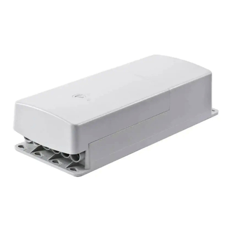
Ewellix SCU 1 User manual

CATEGORY
MAX 2 LINES
Control unit - SCU
INSTALLATION, OPERATION AND MAINTENANCE MANUAL


33
Contents
WARNING
Read this manual before installing, operating or maintaining this
actuator. Failure to follow safety precautions and instructions
could cause actuator failure and result in serious injury, death or
property damage.
1.0 General information......................................................4
1.1 Information on this manual..............................................4
1.2 Explanation of symbols and signal words ......................4
1.3 Limitation of liability ........................................................5
1.4 Copyright.........................................................................6
1.5 Spare parts......................................................................6
1.6 Warranty terms................................................................6
1.7 Customer service ............................................................6
2.0 Safety .............................................................................7
2.1 Use ...................................................................................7
2.2 Responsibility of the owner and processor....................8
2.3 Personnel requirements..................................................9
2.4 Specic dangers .............................................................9
2.5 Safety equipment.......................................................... 11
2.6 Safeguard against restart ............................................. 11
2.7 Modication & Information of device ............................ 11
2.8 Manufacturer‘s declaration of EMC compliance.......... 13
3.0 Technical data............................................................. 19
3.1 Ambient conditions ...................................................... 19
3.2 Product label.................................................................20
4.0 Structure and function...............................................21
4.1 O ve r vi ew ........................................................................21
4.2 Brief description............................................................22
4.3 Special features ............................................................23
4.4 Requirements for 3rd party power supply....................23
4.5 Connections.................................................................. 23
4.6 Operating elements....................................................... 24
4.7 Options .......................................................................... 24
4.8 Accessories...................................................................25
5.0 Transport, packaging and storage ...........................26
5.1 Safety information for the transportation......................26
5.2 Transport inspection..................................................... 26
5.3 Return to the manufacturer...........................................26
5.4 Packaging......................................................................26
5.5 Storage.......................................................................... 27
6.0 Installation and rst operation .................................28
6.1 Installation location .......................................................28
6.2 Inspections prior to rst operation ............................... 28
6.3 Installation..................................................................... 28
6.4 Connection to the actuators .........................................29
6.5 Connection to operating elements ...............................29
6.6 Connection to main power supply................................30
6.7 Requirements concerning the installation of the
actuators with options .........................................................30
6.8 Initial start-up ................................................................ 31
7.0 Operation .....................................................................34
7.1 Safety .............................................................................34
7.2 Actions before use / Preconditions...............................35
7.3 Turn on...........................................................................35
7.4 Turn o...........................................................................36
7.5 Actions during the operation.........................................36
7.6 Emergency disengagement ..........................................37
7.7 Action after use..............................................................38
8.0 Maintenance................................................................39
8.1 Maintenance plan..........................................................39
8.2 Maintenance work.........................................................39
8.3 Measures following completed maintenance...............40
9.0 Malfunctions................................................................ 41
9.1 Malfunction table........................................................... 41
9.2 Start of operation after malfunction repair...................43
10.0 Dismantling................................................................44
10.1 Disposal .......................................................................44
11.0 Appendix ....................................................................45

4
Control unit - SCU
1.0 General information
1.1 Information on this
manual
This manual provides important information on how to work
with the actuator (also called the device) safely and e-
ciently. The manual is part of the device, must always be
kept and should be available for personnel to read at any
time. All personnel working with the device must read and
understand this manual before starting any work. Strict
compliance with all specied safety notes and instructions is
a basic requirement for safety at work. Moreover, the acci-
dent prevention guidelines and general safety regulations
applicable at the place of use of the device must also be
complied with. For better representation of circumstances,
the illustrations in this manual are not necessarily to scale
and may vary from the actual design of the device. All infor-
mation and notes in this manual were compiled with due
consideration given to applicable standards and regulations,
the present status of technology and our years of knowledge
and experience.
Summary of contents
The operation manual serves as a reference work. The infor-
mation therein is organized into four task- and theme-related
parts:
Basic Principles The Basic Principles section gives the ba-
sic knowledge that every user should have.
Normal Operation The Normal Operation section contains
information needed for operating the product under normal
conditions, i.e. undisrupted operation for use according to
its intended application.
Special Operations The Special Operations section de-
scribes all jobs deviating from normal operation, such as in-
stallation, initial start-up, maintenance, xing faults and do-
ing repairs.
Appendix The Appendix contains information that the user
has to be able to access at any time. This includes informa-
tion on using the operation manual (indexes) as well as data
concerning the product itself (technical data).
Aids for accessing information
This manual has access aids that make it easier for you to
quickly access the desired information:
• You can most easily nd all information on a given topic in
the Table of Contents, as a result of the task and theme-re-
lated organization of the operation manual.
• Information on a specic activity or a special topic can be
found most quickly through the Index.
• Within the chapters of the operation manual, you can ori-
ent yourself with the help of the margin notes.
1.2 Explanation of symbols
and signal words
Safety precautions are identied by symbols and signal
words dened on the right hand side of this page.
These signal words indicate the severity of the hazard.
Adhere to these safety precautions and take caution in order
to avoid accidents that may result in personal injuries or
damage to property.

5
1.0 General information
1.3 Limitation of liability
All information and notes in this manual were compiled un-
der due consideration of valid standards and regulations,
the present status of technology and our years of knowledge
and experience. The manufacturer will not be liable for dam-
age resulting from:
• disregarding this manual
• unintended use
• employment of untrained personnel
• unauthorized conversions
• unauthorized technical modications
• manipulation or removal of the screws on the device.
Where the device has been customized, the actual product
delivered may be dierent from what is described in this
manual. In this case, ask Ewellix for any additional instruc-
tions or safety precautions relevant to these actuators.
We reserve the right to make technical modications to the
actuator to improve usability.
Validity
The instructions in this manual refer to the SCU control unit
with the following identication:
• Manufacturer: Ewellix
• Product name: SCU control unit
• Type designation: SCU1, SCU5, SCU9 (SCU4, SCU8 on re-
quest); ⮑ technical data chapter 3 and Appendix
chapter 11)
• Year of manufacture: from 2010
• CE-Mark: according technical documentation
• Serial number: from L04330000.
When the device has been customized by Ewellix, the actual
product delivered may be dierent from what is described in
the manual. In this case, ask Ewellix for any additional in-
structions or safety precautions relevant to these.
We reserve the right to make technical modications to the
device units to improve usability.
Target audience and obligation to read
The operating manual is intended for technical personnel
and authorized users who use the SCU control unit in their
products and work with them. The operating authority deter-
mines who is authorized as a user. We distinguish between
dierent user groups, as the requirements on the users vary,
depending on the activity they perform.
DANGER
Indicates a dangerous situation, which
will lead to death or serious personal
injury, if the precautionary measures are
ignored.
WARNING
Indicates a dangerous situation, which
can lead to minor or moderate injury or
property damage, if the precautionary
measures are ignored.
CAUTION
Indicates a dangerous situation, which
can lead to minor or moderate injury
the precautionary measures are ignored.
NOTICE
Indicates information considered
important, but not hazard-related (e.g.
messages relating to property damage).
NOTE
Emphasizes useful hints and
recommendations as well as information
for ecient and trouble-free operation.

6
Control unit - SCU
6
1.4 Copyright
This manual is protected by copyright law and to be used
exclusively by Ewellix customers internal purpose Passing
this manual on to third parties, duplication of any kind – even
in the form of excerpts – as well as the use and/or disclosure
of the contents without the written consent of the manufac-
turer is not permitted, except for internal purposes.
Violation of Ewellix’s copyright may become the subject of a
future claim for damages.
1.5 Spare parts
This control unit is not designed for repair work by the
owner/operator. All warranty and service claims are void if
repairs are not performed by the manufacturer or another
entity approved by the manufacturer.
Battery (underoor) with battery-charging-board: ZDV-
160208 (2x 12V/2.8Ah)
Ext. Battery charging box: ZDV-160207
Ext. Battery: ZDV160209 (2x 12V/4.5Ah)
Sealing stoppers for sockets “actuator outputs”:
ZDV-160307-0008
Sealing stoppers for socket “operating elements”:
ZDV-160308-0015.
Accessories:
Mains cable: 3pol Schuko ZKA-160637-3500
Mains cable: 3pol SEV ZKA-160638-3500
Mains cable: 3pol UL ZKA-160639-3500
Mains cable: 3pol UL hospital grade ZKA-160640-3500
Mains cable: 3pol UK ZKA-160609-3500.
WARNING
Safety hazard caused by wrong spare parts
Wrong or faulty spare parts can adversely aect safety and
cause damage, malfunctions or total failure.
Therefore:
• Use only genuine spare parts from the manufacturer.
• Spare parts in/on the device may only be replaced by the manu-
facturer.
If the device cannot be repaired on site by authorized per-
sonnel it must be dismantled and sent to the manufacturer.
1.6 Warranty terms
The warranty terms are included in the manufacturer’s terms
and conditions contained in the Ewellix sales contract that
governs this sale.
1.7 Customer service
Ewellix Customer Service is always available to provide
technical information and to answer questions. The contact
information for Ewellix Customer Service can be found on
www.ewellix.com.
In addition, our employees are always interested in acquiring
new information and experience gained from practical appli-
cation; such information and experience may help improve
our products.

7
2.0 Safety
7
2.0 Safety
This section provides an overview of important safety
aspects of installing, operating and maintaining this device.
Disregarding this manual and safety regulations specied
therein may result in considerable danger and possible
serious injury or death or damage to device or equipment.
The SCU control unit was designed and build in accordance
with the latest technical standards and accepted rules.
EU-Conformity is documented with the technical
documentation.
2.1 Use
2.1.1 Intended Use
The SCU control unit was designed and built in accordance
with the latest technical standards and accepted safety
rules.
The intended purpose is described in these instructions.
The authorized use of the SCU control unit is:
“Control up to six actuators for push- or pull loads”.
NOTICE
The control unit can only be parametrized for the actuators
of Ewellix. Please contact customer services to nd out
which actuators are approved for the SCU!
NOTE
For the operations data, please see the Appendix of this op-
erating manual.
If you use the SCU control unit for any use other that cited,
the manufacturer cannot be held the responsibility for defect
or damage resulting from this.
It is only intended for interior use and is implemented in
medical devices as well as in industrial and construction
technology.
Range of environmental conditions:
• Ambient temperature: 5°C to + 40 °C
• Relative humidity : 5% to 85%
• Atmospheric pressure: 700 hPa to 1060 hPa
• Use and operate at an altitude of 3000m (MOPP)
• Overvoltage category II
• Pollution degree classication 2.
2.1.1.1 Product life time
The SCU control unit is designed for a service life of 10
years or at least 100’000 cycles of operation per channel.
2.1.1.2 User groups
The organization and implementation of the operation man-
ual takes into account the dierent user groups
To ensure safety, we place requirements on the users of the
SCU control unit that must be adhered to under all circum-
stances. Only persons who meet the requirements are enti-
tled to use the SCU control unit.
We refer to all persons who operate, use, commission the
control unit, process it further or pass it on for further pro-
cessing as user groups. As the requirements of these user
groups strongly depend on their role, we distinguish be-
tween the following user groups:
The operating authority is the contractual partner of the
person doing the further processing or the reseller. They can
impose legal conditions on the operating authority when
purchasing the control unit. The operating authority ensures
that the user is instructed in the authorized use of the
equipment.
The processor is the contractual partner of the reseller or
the manufacturer. He assembles the control unit into a total
device. He is authorized by the manufacturer of the SCU
control unit to use the control unit in accordance with the
regulations and has the necessary expert knowledge.
The technician has the professional technical training to
implement the SCU control unit according to its authorized
use. Apart from the chapter on Safety, he is also familiar
with the chapter on Special operating modes. He will nd
the required technical data in the Appendix.
The reseller forwards the machine. Every other person who
uses the SCU control unit we dene as an operator. The
operator must have read the Safety chapter in this manual
before using the machine. Moreover, he must be instructed
about the normal operation by the operating authority.
2.1.1.3 Types of operation
The SCU control unit is exclusively intended for intermittent
operation (⮑ Technical data, page 43).
2.1.1.4 Danger zones
We dierentiate between two danger zones that must be
observed, depending on user role.

8
Control unit - SCU
8
The danger zone covering persons includes, aside from the
actual user, third persons as well (other personnel, visitors,
patients etc.) In case of injury, the operating authority is
responsible.
The danger zone device comes under the user group
Executor and Technician and covers the SCU control unit
and all the mounted-on elements.
2.1.2 Unintended Use
Any use other that the intended use, or modications to the
device without the manufacturer’s written agreement, or
operation beyond the technical limits, is considered
unauthorized.
See technical operating limits in the technical data of this
manual and on the label of the SCU.
NOTE
Any unauthorized use of the device can cause personal injury
and property damage. Always adhere to the instructions given in
this manual.
The SCU control unit is suitable only for internal use and
must not be subjected to weathering, strong UV radiation or
explosive atmospheric media. Specic application exemp-
tions are:
• Flammable anesthetic mixture with air
• Flammable anesthetic mixture with oxygen or nitrous oxide
• Increased radiation.
WARNING
Risk from misuse
Any utilization of this device beyond its intended purpose may
lead to potentially hazardous situations.
Therefore:
• Strictly adhere to all safety precautions and instructions in this
operating manual.
• Do not make this device subject to weather conditions, strong UV
rays, corrosive or explosive air media as well as other aggressive
media.
• Do not modify, retool or change the structural design or individual
components of the actuator.
• Never use the device outside of the technical application and op-
erational limits.
2.1.3 Essential performance
Supply electromechanical actuators / pillars by command.
2.2 Responsibility of the
owner and processor
The device is designed for commercial applications by its
owner or processor. The processor is the contracting part-
ner of the reseller or the manufacturer. The processor in-
stalls the device in a complete system (application).
The owner or processor of the system is therefore subject to
the requirements of the Occupational Health and Safety Act.
In addition to the safety instructions in this manual, the
owner or processor must do the following concerning these
safety and accident prevention guidelines and environmental
protection regulations applicable to the site of the system’s
installation:
• Inform themselves of applicable industrial safety regula-
tions. They must also determine additional hazards that
arise due to the specic working conditions prevailing at
the site where the device is installed using risk assess-
ment. The risk assessment must be implemented in the
form of work instructions for device operation.
• Conrm that the work instructions created for the system,
including the device satisfy current legal requirements and
must alter the instructions accordingly.
• Clearly regulate and specify the responsibilities for instal-
lation, operation, maintenance, and cleaning.
• Ensure that all employees who deal with the device have
read and understood this manual.
• Provide personnel with the required protective equipment.
• Provide training for personnel at regular intervals and in-
form personnel of the hazards.
In addition, the owner or processors must ensure that the
device is in adequate working condition. They must do the
following:
• Ensure that the maintenance intervals described in these
instructions are complied with.
• Have all safety devices inspected regularly for function and
completeness.
Areas of responsibility
Dierent areas of responsibility, corresponding to the dier-
ent user groups, arise.
The Operating Authority has the responsibility for the danger
zone covering persons and ensures that only authorized and
instructed users work with the SCU control unit. He or she is
responsible for the following:
• Determining the persons who may use the SCU control
unit (authorized persons).
• Instruction of the users.
• Complying with all relevant legal conditions and regula-
tions.

9
2.0 Safety
9
NOTICE
The Operating Authority may only authorize such persons for
using the SCU control unit, who conform to the requirements for
the user roles.
The processor is responsible for:
• Generation of a CE-conformant operation manual of the
device in which the SCU control unit has been integrated.
• Adherence to the safety regulations in accordance with
this operating manual.
The technician is responsible for:
• Observing the manufacturer’s instructions and the safe-
set-up of interfaces with other equipment.
• Installation and use of the SCU control unit in accordance
with its intended purpose-conformant use.
• Installation of optional modules and connecting cables.
The reseller is responsible for:
• Passing on this operating manual and the SCU control unit
to the executor.
• Passing on of a CE-conformant operating manual and the
device in which the SCU control unit has been integrated
to the Operating Authority.
The operator is responsible for:
• Ensures that nobody is endangered owing to the operation
of the SCU control unit.
• Operation of the SCU control unit in normal operation.
• Immediate and appropriate reaction to malfunctions.
2.3 Personnel
requirements
WARNING
lmproper installation, operation and maintenance can result
in serious injury, death or property damage.
Use only qualied, instructed, or trained personnel (as described
below) who have read, understand and follow these instructions.
2.3.1 Qualications
The following qualications are specied for dierent areas
of activity listed in this manual:
• An instructed person (operator): Instructed by the cus-
tomer in an orientation session on the assigned tasks and
possible dangers arising from in case of improper behav-
ior.
• Qualied personnel: Based on their professional training,
know-how and experience as well as knowledge of the ap-
plicable standards and regulations are able to inde-
pendently perform assigned work activities and to detect
and avoid possible dangers.
• Professional electrician: Based on his/her professional
training, know-how and experience as well as knowledge
of the applicable standards and regulations is able to inde-
pendently perform work on electrical systems and to de-
tect and avoid possible dangers.
In addition, the professional electrician has been trained
for the special location where he/she works and knows the
relevant standards and regulations.
Only persons who can be expected to perform their tasks
reliably are permitted as personnel. Persons whose reaction
capabilities are impaired, e.g. through the use of drugs, al-
cohol or medication for example, are not permitted.
2.4 Specic dangers
The manufacturer has constructively, and with protective
measures, minimized the eects of existing hazards. Pay at-
tention to the residual hazards and potential countermeas-
ures described and the warnings in the following chapters.
2.4.1 Residual hazards to people, objects
and property
Keep in mind the following residual dangers and the possi-
ble countermeasures in handling the SCU control unit.
DANGER
Danger to life caused by electric current.
Touching conductive parts causes a direct danger to life.
Damage to insulation or individual components can cause
danger to life.
Therefore:
• In the event of damage to insulation, switch o the power supply
immediately and have the defective parts repaired.
• Work on the electrical system must he carried out only by skilled
electricians.
• De-energize the machine for all work on the electrical system.
• Before maintenance, cleaning or repair work, switch o the power
supply and perform lockout procedures so it cannot he turned on
again.
• Do not bridge fuses or make them ineective. When changing
fuses, make sure you use the correct amperage.
• Keep moisture away from conductive parts. If you do not, this can
cause short circuit.

10
Control unit - SCU
10
WARNING
Electrical shack hazard
Check the mains voltage corresponds to the nominal values on
the product label.
• Ensure that power cables cannot become pinched or damaged.
• Warning regarding electrical shock owing to damaged plugs or da-
maged network cables. Never touch a damaged network plug or a
damaged network cable when the SCU control unit is running,
since the SCU control unit is supplied with 120 VAC or 230 VAC.
• Ensure, before you pull a defective plug out of the plug socket,
that the SCU control unit is disconnected from the power supply.
WARNING
Unintended, uncontrollable movement
• Due to a defect of a component, an uncontrollable movement of
the connected actuator[s) can occur.
• In worst case RAM or ROM failure can lead to a false or auto mo-
tion. This kind of failure has a low failure probability and it occurs
in such a way that a motion is started.
• If the button of the hand switch sticks when releasing it and the
user doesn't press the button for the opposite direction (⮑
chapter 7.3) then an auto motion occurs.
WARNING
Specic dangers during cleaning or washing the control unit
SCU
The control units are designed to comply with IPX4.
The cleaning or washing with water including chemical additives
must be pH-neutral. Excessively acidic or alkaline washing water
can destroy metal and plastic components of the control unit.
Manually and mechanically operated high-pressure steam
cleaners must not be used. Only isopropyl alcohol cleaning
agent may be used for disinfecting by manual wiping.
A SCU control unit must never be washed in a washing machine
or other equipment. The control unit would be destroyed by the
penetration of liquid.
The plastic housing must be checked periodically (every six
months) for mechanical damage (cracks).
WARNING
Injury due to cracks and related openings in the housing of the
actuator and/or its accessories:
If the housing is damaged due to stock, breakage or heavy wear,
stop using the device and follow the dismantling instructions.
CAUTION
Please be aware of damage to people or property as the result of
incorrect operation. Incorrect operation can endanger people in
the danger zone or objects.
• Before pressing a button on the operating device, ensure that you
press the right button.
• Take appropriate measures to ensure that the operating device
cannot be operated.
CAUTION
No function is considered as a safe condition.
CAUTION
The SCU control unit is only suitable for interior applications
and must not be subjected to weathering, strong UV radiation or
corrosive or explosive air (⮑ Ambient conditions).
The SCU control unit may only be operated when the safety
protective cover (⮑ g 8) is mounted.
CAUTION
Failure of the control unit due to interruption to the mains power
or an electronic defect should not pose any hazard to the
patient, to the operator or to the servicing personnel.
Ewellix actuators should be operated in accordance with the
application specied on the type label.
The nominal data for the actuators and the control unit must be
veried at the same time of installation. The ratings on the data
should not be exceeded. If this information is disregarded, the
actuator and the control unit will be damaged irreparably. Risk of
personal injury remains.
CAUTION
Any overload on the control unit will trip a temperature switch
in the mains transformer. After cooling of the transformer, the
thermal protector will reset, so the control unit SCU is ready
again to control the actuators.
CAUTION
Electric shock hazard
Take care about damage to the SCU from water sprays. The
control unit SCU is splash-proofed according to IPX4. Prevent
the SCU from being subjected to water sprays or hosing during
the operation time.
NOTICE
Prolonged overload will result in irreparable damage to the
control unit.
2.4.2 Specic dangers SCU with
batteries
Replacement batteries should only be ordered from Ewellix,
since they are a special type. The old batteries must be
properly disposed of. The user’s maintenance personnel
must be given instructions by the ultimate manufacturer on
opening and closing the battery compartment lid and on re-
placing the batteries.
WARNING
If unintended movements can cause serious injury, additional
protective means must be installed to stop or avoid such
movements.
WARNING
Disconnection from the mains power supply will not prevent
movement of the actuators in case of an electric defect while
batteries are connected.

11
2.0 Safety
11
2.5 Safety equipment
WARNING
Danger due to malfunctioning safety equipment
For safe operation, be sure all safety equipment is in good
working order.
Therefore:
• Always check functionality of safety equipment according to the
maintenance plan.
• Never disengage safety equipment.
• Safety equipment may never be by-passed or modied.
Integration in an emergency-stop system
required (for certain applications)
WARNING
Electric shock hazard
The SCU control unit do not have an on/o switch. If required
to be switched o, for example in an emergency, the control
unit must be disconnected from the power supply. Only this
measure will de-energize the control units. Applications where
the control units are built in must provide an emergency stop
switch or isolation from the power supply on all poles. Additional
protective means might be necessary in case of battery options.
The device is only intended for installation into an applica-
tion or system. It does not have its own operating control el-
ements and does not have an independent emergen-
cy-stop-function. Install the device so that it is part of an
emergency shut-o system and can be stopped if
necessary.
The emergency shut-o system has to be connected in such
a way that a disruption of the power supply or the reactiva-
tion of the power supply after a power disruption cannot
cause a hazardous situation for persons and objects.
The emergency shut-o systems must always be freely
accessible.
2.6 Safeguard against
restart
To secure the SCU control unit against unintentional restart:
Pull the power line plug o the control unit from the main
supply.
DANGER
Life-threatening situation through unauthorized restart
For work in hazard zones, there is a risk that the power supply
is turned on without prior authorization. This presents a life-
threatening situation for people in the hazard zone.
Therefore:
• Follow the information concerning the safeguarding against
re-starting of the power supply in the chapters of this operating
manual.
• Always follow the process to safeguard against a restart as de-
scribed below.
Protect the SCU control unit against restart:
0.1. Pull the power line plug out of the power outlet.
0.2. In case the SCU control unit is equipped with a bat-
tery, ensure to remove the battery.
2.7 Modication &
Information of device
WARNING
To avoid hazardous situations and to ensure optimal
performance, do not make any changes or modications to the
device unless they have been specically authorized by Ewellix.
2.7.1 Warning labels
For SCU control units no special warning labels are applied.
WARNING
Danger of injury because of illegible symbols
Over the course of time stickers and decals may become dirty or
illegible for various reasons.
Therefore:
• Keep any safety, warning and operation related decals in legible
condition at all times.
• Replace damaged decals or stickers immediately.
2.7.2 Information labels & lights
Labels
On the back side of the SCU control unit are two labels (⮑
fig. 1):
• Type label (⮑ chapter 3.2 Product label)
• Software parameter label (⮑ g. 2).
Fig. 1
Location of type label and SCU parameter label

12
Control unit - SCU
12
Fig. 2
Example “Smart Control Parameter” (SCP-Label)
An additional label (inside, under the case cover, ⮑ g. 3)
shows the socket pin assignment inputs / outputs (linear ac-
tuators, telescopic pillars, switches, operating elements,
battery, etc.)
Fig. 3
Example SCU socket pin assignment
For detailed information about the SCP-label (⮑ g. 2) and
the corresponding description label of the SCU sockets (la-
bel ⮑ g. 3) see type key (chapter 11.2.3) or contact
Ewellix business support!
Power indicator light
The indicator light secures the visualization of the readiness
of the control unit SCU (⮑ g. 4).
NOTICE
The SCU control unit is equipped with a green indicator light LED
to indicate ready for normal use.
Fig. 4
Power indicator light
In addition to that a LED on the connected operating ele-
ment (ex. hand switch) shows the status of the functionality
and the status about the SCU and the connected actuators
and gives (optional) information about the loading capacity
of a used battery.
CAUTION
Push-to-run operation (recommended):
The connected actuators, pillars operate as long as the button
on the hand switch is pressed. A green pilot lamp indicates the
actuation. The relevant function (up/down) is determined and
triggered by the button actuation.
If the actuator does not have signals to indicate operation,
depending on the application, it is recommended to have an
operational signal installed in the application.
Protective Earth, metal pin
The SCU control units SCU5 & SCU9 are dened as class I
devices. These models are connected to PE (protection
earth) on side of main supply. This PE is also connected to
the metal pin next to the main supply connector (⮑ g. 5)
on the SCU. This bolt pin can also be used to connect the -
nal application to ground (PE) with a protection earth con-
ductor (green/yellow).
LED

13
2.0 Safety
13
Fig. 5
Protective earth, metal pin
At this pin there is a possibility to connect other devices
from the applications to earth ground. This can also help in
case of improvements with EMC measurements.
NOTE
Take care! The maximum torque for the 6 edge screw is 0,8 Nm.
2.8 Manufacturer‘s
declaration of EMC
compliance
This section is only mandatory, if the devices are approved
and attended for use in medical applications or environment
(according IEC60601-1-2 ed. 4) This chapter shows the re-
sults and potential about EMC issues.
2.8.1 Instructions for use
Professional healthcare facility environment
Physician oces, dental oces, clinics, limited care facili-
ties, freestanding surgical centers, freestanding birthing
centers, multiple treatment facilities, hospitals (emergency
rooms, PATIENT rooms, intensive care, surgery rooms, ex-
cept near HF SURGICAL EQUIPMENT, an MR system out-
side a RF shielded room of an ME SYSTEM for magnetic
resonance imaging).
Essential performance
The essential performance about the SCU control unit is
„supply of electro-mechanic actuators and pillars on com-
mand”. The risk management (Document L5678,0002) iden-
ties the functions about safety of these control units. All
features or functions are performed properly. Unacceptable
risks for patients, operators or others are performed and as-
sessed to prevent or reduce harm. The follow points identify
and describe the EMC-risks about the SCU control unit ac-
cording the EMC-measurements:
Warning against the stacking of equipment
WARNING
Stacked with other equipment
Use of this equipment adjacent to or stacked with other
equipment should be avoided because it could result in improper
operation. If such use is necessary, this equipment and the other
equipment should be observed to verify that they are operating
normally.
List of cables, length of cables, accessories
WARNING
Use of accessories, transducers and cables
The use of accessories, transducers and tables other than
those specied or provided by the manufacturer of this
equipment could result in increased electromagnetic emissions
or decreased electromagnetic immunity of this equipment and
result in improper operation.

14
Control unit - SCU
14
RF Communication Equipment
WARNING
Portable RF communications equipment
Portable RF communications equipment (including peripherals
such as antenna cables and external antennas) should he
used no closer than 30 cm (12 inches) to any part at the SCU,
including cables specied by the manufacturer. Otherwise,
degradation of the performance of this equipment could result.
2.8.2 Technical description
Requirements applicable to all ME equipment
and ME systems
This chapter describes precautions to be taken to prevent
adverse events to the patent and operator due to electro-
magnetic disturbances.
2.8.2.1 Compliance for each Emissions and
Immunity standards
The SCU control unit is intended for use in the electromag-
netic environment specied. It complies with the standard
for emission class and group and immunity test level as
follows.
Description Plug Country Drawing-No Length Comment
Power cable, straight Schuko Euro ZKA-160637-3500 3,5 m
Power cable, straight SEV CH ZKA-160638-3500 3,5 m
Power cable, straight UL/CSA (NEMA 5-15p) USA/CAN ZKA-160639-3500 3,5 m SJT-cable
Power cable, straight UL/Hospital grade (NEMA 5-15p) USA/CAN ZKA-160640-3500 3,5 m SJT-cable
Power cable, straight British plug UK ZKA-160609-3500 3,5 m
Description Plug Drawing-No Type Length
Connecting cable coiled: SCU – Hand switch HD 15p 160600-1350 15 x AWG30 1,3/2,3 m
Connecting cable straight: SCU – Foot switch HD 15p 160632-2500 10 x AWG28 2,5 m
Connecting cable coiled: SCU – Foot switch HD 15p 160633-2500 10 x AWG28 1,2/2,5 m
Connecting cable straight: SCU – Desk switch HD 15p 160634-2500 10 x AWG28 2,5 m
Communication cable HD 15p / USB 160679-1500 3 x AWG24 1.5 m
Description Plug Drawing-No Type Length
Connecting cable straight:SCU – MD DIN 8p
Connecting cable straight: SCU – CAMT DIN 8p – Molex 6p
DIN 8p – open wire
777400-1000
777400-2300
2 x AWG16 &
4 x AWG24
1 m
2,3 m
Connecting cable straight: SCU – RU 160601
Connecting cable straight: SCU – MAX1, MAX3 DIN 8p 160622 2 x AWG18 &
5 x AWG24 1,5 m
Connecting cable straight: SCU – THG,TLG,TLT DIN 8p 1 m
2,3 m
Connecting cable straight: SCU – TFG10 DIN 8p
Power cables (Main <-> SCU control unit)
Connection cable (SCU control unit <-> Operating elements / RS232)
Connection cable (SCU control unit <-> Linear Actuators / Pillars)

15
2.0 Safety
15
Emissions test Compliance Electromagnetic environment - guidance
RF emissions CISPR 11 Group 1
The SCU uses RF energy only for its internal function. Therefore, its RF
emissions are very low and are not likely to cause any interference in
nearby electronic equipment.
RF emissions CISPR 11 Class B
The SCU is suitable for use in all establishments, including domestic
establishments and those directly connected to the public low-voltage
power supply network that supplies buildings used for domestic
purposes.
Harmonie emissions IEC 61000-3-2
[Class A, B, C, D, Not
applicable or No power
network input]
Voltage uctuations /
icker emissions IEC 61000-3-3
[Complies, Not applicable,
No power network input]
CISPR 11 Gr. 1 Cl. B
The SCU is intended for use in the electromagnetic environment specied below. The customer or the user
of the SCU should assure that it is used in such environment.
Immunity test IEC 60601 test level Compliance level Electromagnetic environment-guidance
Electrostatic discharge (ESD)
IEC 61000-4-2
± 8 kV contact
± 2, ± 4, ± 8, ± 15 kV air ± 8 kV contact
Floors should be wood, concrete, or ceramic tile. If
oors are covered with synthetic material, the relative
humidity should be at least 30%
Electrical fast transient/bust
IEC 61000-4-4
± 2 kV, 100 kHZ
for power supply lines
± 1 kV, 100 kHZ
for input/output lines
± 2 kV, 5 and 100 kHZ
for power supply lines
± 1 kV, 100 kHZ
for input/output lines
Mains power quality should be that of typical
commercial or hospital environment.
Not applicable for DC and I/O if cable <3 m
Surge
IEC 61000-4-5
± 0,5 , ±1 kV
line(s) to line(s)
± 0,5, ±1, ± 2 kv
line(s) to earth
± 0,5 , ±1 kV
line(s) to line(s)
± 0,5, ±1, ± 2 kv
line(s) to earth
Mains power quality should be that of typical
commercial or hospital environment.
Not applicable for DC and I/O if cable <3 m
Voltage dips, short
interruptions and voltage
variations on power supply
inputs lines
IEC 61000-4-11
0% UT: 0,5 cycle
At 0°, 45°, 90°, 135°, 180°,
225°, 270° and 315°
0% UT: 1 cycle
at 0°
0% UT: 250/300 cycle
At 05
0% UT: 25/30 cycle
At 0°
0% UT: 0,5 cycle
At 0°, 45°, 90°, 135°,
180°, 225°, 270° and
315°
0% UT: 1 cycle
at 0°
0% UT: 250/300 cycle
At 05
0% UT: 25/30 cycle
At 0°
Mains power quality should be that of typical
commercial or hospital environment.
Not applicable for DC and I/O if cable <3 m.
If the user of the SCU requires continued operating
during power mains interruptions, it is recommended
that the SCU be powered from an uninterruptible
power supply or batery.
UT is the a.c. mains voltage (120V/230V AC) prior to
application of the test level
Power frequency (50/60 HZ)
magnetic led
IEC 61000-4-8
30 A/m
50/60 HZ
30 A/m
50/60 HZ
Power frequency magnetic elds should be at levels
characteristics of a typical location in a typical
commercial or hospital environment.
Electromagnetic immunity environment tested
The SCU is intended for use in the electromagnetic environment specied below. The customer or the user
of the SCU should assure that it is used in such environment.

16
Control unit - SCU
16
Electromagnetic immunity environment tested
Portable and mobile RF communications equipment should be used no closer to any part of the SCU, including cables, than
the recommended separation distance calculated from the equation applicable to the frequency of the transmitter.
These guidelines may not apply in all situations. Electromagnetic propagation is aected by absorption and reection from
structures, objects and people. Field strengths from xed transmitters, such as base stations for radio (cellular/cordless)
telephones and land mobile radios, amateur radio, AM and FM radio broadcast and TV broadcast cannot be predicted theo-
retically with accuracy. To assess the electromagnetic environment due to xed RF transmitters, an electromagnetic site sur-
vey should be considered.
Immunity test IEC 60601 test level Compliance level Electromagnetic environment
Conducted RF
IEC 61000-4-6
3 V...
150 kHz to 80 MHz outside ISM
bands and radio amateur band*
10 Vrms
150 kHz to 80 MHz outside ISM
bands and radio amateur band*
If the measured eld strength in the
location in which the SCU is used
exceeds the applicable RF
compliance level, the SCU should be
observed to verify normal operation.
If abnormal performance is
observed, additional measures may
be necessary, such us reorienting or
relocating the SCU.
6 V...
150 kHz to 80 MHz in ISM bands
and radio amateur band*
10 Vrms
150 kHz to 80 MHz in ISM bands
and radio amateur band*
Radiated RF
IEC 61000-4-3
10 V/m
80 MHz to 2.7 GHz
80% AM at 1 kHz
10 V/m
80 MHz to 2.7 GHz
80% AM at 1 kHz
Minimum separation distance shall
be calculated by following equation:
E = P
6
d
E is the immunity test level in [V/m]
d is the minimum separation in [m]
P is the maximum power in [W]
Proximity eld from RF
wireless communication
equipment
IEC 61000-4-3
27 V/m
380-390 MHz
50% PM 18 Hz
28 V/m
430-470 MHz
FM ±5 kHz devation,
1kHz sine
9 V/m
704-787 MHz
50% PM 217 Hz
28 V/m
800-960 MHz
50% PM 18 Hz
28 V/m
1700-1990 MHz
50% PM 217 Hz
28 V/m
2400-2570 MHz
50% PM 217 Hz
9 V/m
5100-5800 MHz
50% PM 217 Hz
27 V/m
380-390 MHz
50% PM 18 Hz
28 V/m
430-470 MHz
FM ±5 kHz deviation,
1kHz sine
9 V/m
704-787 MHz
50% PM 217 Hz
28 V/m
800-960 MHz
50% PM 18 Hz
28 V/m
1700-1990 MHz
50% PM 217 Hz
28 V/m
2400-2570 MHz
50% PM 217 Hz
9 V/m
5100-5800 MHz
50% PM 217 Hz
RF wireless equipment maximum
output power and separation
distance tested (at 30 cm):
TETRA 400: max 1.8 W
GMRS 460, FRS 460: max 2 W
LTE Band 13 and 17: max 0.2 W
GSM 800/900: max 2 W
TETRA 800: max 2 W
iDEN 820: max 2 W
CDMA 850: max 2 W
LTE Band 5: max 2 W
GSM 1800/1900: max 2 W
CDMA 1900: max 2 W
DECT: max 2 W
LTE Band 1,3,4 and 25: max 2 W
UMTS: max 2 W
Bluetooth: max 2 W
RFID 2450: max 2 W
LTE Band 7: max 2 W
WLAN 802.11 a/n: max 0.2 W
Interference may occur in the vicinity
of equipment marked with the
following symbol:
*The ISM (industrial, scientic and medical) bands between 150 kHz and 80 MHz are 6.765 - 6.795 MHz, 13.553 - 13.567 MHz, 26.957 - 27.283 MHz and 40.66 - 40.7 MHz. The amateur
radio bands between 0.15 MHz and 80 MHz are 1.8 MHz - 2 MHz, 3.5 - 4.0 MHz, 5.3 - 5.4 MHz, 7 - 7.3 MHz, 10.1 - 10.15 MHz, 14 - 14.2 MHz, 18.07 - 18.17 MHz, 21.0 - 21.4 MHz, 24.89 -
24.99 MHz, 28.0 - 29.7 MHz and 50.0 - 54.0 MHz.
If the measured eld strength in the location in which the CAMT is used exceeds the applicable RF compliance level above, the CAMT should be checked to verify normal operation. If
abnormal performance is observed, additional measures may be necessary, such as reorienting or relocating the CAMT.

17
2.0 Safety
17
2.8.2.2 Results and Deviations from Standards
and allowances used
There are no deviations (⮑chapter 2.8.2.1)
Type of measure Requirement - Test Result/Comment Verdict
Emission Class Class B –
Group 1 or 2 Group 1 –
CISPR 11,14-1, or… CI SPR11 –
Conducted RF Emission – P
Radiated RF Emission – P
Disturbance Power /if applicable) –N/A
Harmonic Distortion per IEC 61000-3-2 (Class A,B,C,D) Class A P
Voltage Fluctuation and Flicker per IEC 61000-3-3 – P
Immunity Electrostatic discharges IEC 61000-4-2 P
Radiated RF EM Fields IEC 61000-4-3 P
Radiated RF EM Fields and Proximity Wireless elds IEC 61000-4-3 P
Electrical Fast Transients and bursts IEC 61000-4-4 P
Surges IEC 61000-4-5 P
Conducted Disturbances, induced by RF elds IEC 61000-4-6 P
Voltage Dips and Interruptions IEC 61000-4-11 (for EUT
120Vac/60Hz) P
Rated Power-frequency Magnetic elds IEC 61000-4-8 P
Recommended separation distances between portable and mobile RF communications equipment
and the SCU
The SCU is intended for use in the electromagnetic environment in which radiated RF disturbances are controlled. The cus-
tomer or the user of the SCU can help prevent electromagnetic.
The SCU intended for use in the electromagnetic environment in which radiated RF disturbances are controlled. The cus-
tomer or the user of the SCU can help prevent electromagnetic interference by maintaining a minimum distance between
portable and mobile RF communications equipment (transmitters) and the SCU as recommended below, according to the
maximum output power of the communication equipment.
Recommended separation distances between portable and mobile RF communications equipment and the CAMT
The CAMT is intended for use in the electromagnetic environment in which radiated RF disturbances are controlled. The customer or the
user of the CAMT can help prevent electromagnetic interference by maintaining a minimum distance between portable and mobile RF
communications equipment (transmitters) and the CAMT as recommended below, according to the maximum output power of the
communication equipment.
Rated maximum
output power of
transmitter [W]
Separation distance according to frequency of transmitter [m]
150 kHz to 80 MHz outside ISM
and radio amateur bands *
150 kHz to 80 MHz
in ISM and radio
amateur bands *
80 MHz to 2700 MHz
(for dene RF Wireless transmitters
see table before)
d = 0,35√P **
0,01 0,04 0,12 0,06
0,1 0,13 0,38 0,19
10,40 1,2 0,60
10 1,3 3,8 1,9
100 4,0 12 6,0
For transmitters rated at a maximum output power not listed above, the recommended separation distance d in meters [m] can be
determined using the equation applicable to the frequency of the transmitter, where P is the maximum output power rating of the
transmitter in watts [W] according to the transmitter manufacturer.
E = P
6
d
*The ISM (industrial, scientic and medical) bands between 150 kHz and 80 MHz are 6.765 - 6.795 MHz, 13.553 - 13.567 MHz, 26.957 - 27.283 MHz and 40.66 - 40.7 MHz. The amateur
radio bands between 0.15 MHz and 80 MHz are 1.8 MHz - 2 MHz, 3.5 - 4.0 MHz, 5.3 - 5.4 MHz, 7 - 7.3 MHz, 10.1 - 10.15 MHz, 14 - 14.2 MHz, 18.07 - 18.17 MHz, 21.0 - 21.4 MHz, 24.89 -
24.99 MHz, 28.0 - 29.7 MHz and 50.0 - 54.0 MHz.
**Formulas coming from Ed.3 of the IEC 60601-1-2

18
Control unit - SCU
18
2.8.2.3 Maintaining BASIC Safety and Essential
performance
Its mandatory to maintain the SCU control unit to save the
essential performance for the expected Service life.
One time approved in the nal application no change is al-
lowed due to the EMC inuence.
NOTE
Do not change the once installed nal application due to EMC
view.
WARNING
This product was tested against actual conditions of frequency
wireless environment present in Europe.
2.8.3 Environment nal application
In dependence of the nal application and the Environment
EMC-Tests (Immunity and Emission) are necessary to be in
accordance with the standards:
• Medical electrical equipment:
-Emission: IEC / EN 60601-1-2 (4th ed.)
-Immunity: IEC / EN 60601-1-2 (4th ed.)
• Industrial environment (Generic Standards):
-Emission: IEC / EN 61000-6-2
-Immunity: IEC / EN 61000-6-4
• Residential, commercial and light-industrial environments
(Generic Standards):
-Emission: IEC / EN 61000-6-3
-Immunity: IEC / EN 61000-6-1.

19
3.0 Technical data
19
3.0 Technical data
NOTE
The technical data (dimensions, weight, output, connection
values etc.) can be found in the enclosed drawings and data
sheets (⮑Appendix).
The datasheet of the SCU control units (⮑ chapter
Appendix 11) provides information on the product types
SCU1 (DC supply), SCU5 and SCU9 (AC supply, class I).
Other models are SCU4 and SCU8; these control units are
similar to SCU5 and SCU9, but are dened as device class II
(without connection to protective earth, but designed with
double insulation from main supply).
For detailed Information contact business support of Ewellix.
Content
• Features
• Technical data
• Dimensional drawing
• Connecting diagram
• Suitable actuators, pillars and accessories
• Pinning of limit switch connection
• Accessories (cables, batteries)
• Type key SCU - Model
• Type key SCU Software Parameter.
3.1 Ambient conditions
The SCU control unit are suitable for indoor use only and
must not be exposed weathering, strong UV-radiation elds
or corrosive or explosive atmospheric media.
• Ambient condition
• Temperature range: +5 °C to +40 °C
• Atmospheric humidity: 5% to 85%
• non-Condensing
• Atmospheric pressure: 700 to 1060 hPa
• IPX4
• Height above sea level: 3 000 m (MOPP)
• Overvoltage category II
• Pollution degree 2.
Table 1
Duty cycle
Information Value Unit
ON/OFF
Maximum operating time 1min
Break until next operation 9 min
Short time operation
Maximum operating time 2min

20
Control unit - SCU
3.2 Product label
The product label provides the following Information:
Fig. 6
Type label
Type Label:
1. Type designation
2. Manufacturer
3. Frequency
4. Maximum current consumption
5. Duty cycle of operation
6. Serial number
7. IP protection class
8. Input Voltage
9. Output Voltage
10. Software number & Version
11. Maximum output current
12. Manufacturer’s address
13. Date of manufacture (month, year)
14. Disposal information
15. CE mark
16. Recommendation to read operating manual
17. UL mark
18. For indoor use only
19. Designation of origin
1 2 4 5 6
7
8910
11 12 13 14 15
3
16 17 1918
This manual suits for next models
2
Table of contents
Other Ewellix Control Unit manuals
Popular Control Unit manuals by other brands

Tyco Fire Product
Tyco Fire Product RAPID RESPONSE RSV-1 manual

Ai-Thinker
Ai-Thinker TB-05 specification

GEM
GEM 205 Installation, operating and maintenance instructions

Det-Tronics
Det-Tronics Eagle Quantum Premier EQ3900K Series instructions

Miele professional
Miele professional A 306 operating instructions

LEVTECH
LEVTECH LSP-SC2-WIFI user manual