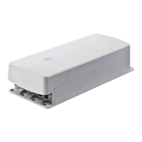
Ewellix SCU User manual

SCU
Brief instructions for
initialization
INSTALLATION INSTRUCTIONS
Safety, Operating manual, Troubleshooting
Before start-up, please read the operating instructions for the SCU control unit
carefully and pay special attention to the safety notes. The relevant notes an
operating manual can be found at https://medialibrary.ewellix.com/asset/16223.
www.ewellix.com/en/global/products/linear-actuators/control-units/scu.
Overview and connections for the SCU
control unit Fig. 1
Overview of SCU control unit, without protective cover
1
2
3
5
4
6
7
8
9
10
11
12
13
14
15
16
1. Housing
2. Space for software data label
3. Connection for operating elements (sockets 8, 9, 10)
4. Connection for 4 external end switches (socket 7)
5. Fastening for safety protective cover
6. Cable guides
7. Installation holes (4)
8. Under-oor rechargeable battery
9. Connection for operating actuators and pillars (sockets 1 to 6)
10. Not occupied (sockets 15, 16)
11. Not occupied (socket 14)
12. Optional rechargeable battery connection (socket 13)
13. Operational voltage indicator (not visible on this image)
14. Communication interface (socket 12)
15. Operational earthing bolt (not visible on this image)
16. Mains connection or connection for source of DC voltage (socket 11)
ewellix.com
© Ewellix
All contents of this publication are the property of Ewellix, and may not be reproduced or given to third parties (even extracts) without permission. Although great care has been taken in the
production of this catalog, Ewellix does not take any responsibility for damage or other loss resulting from omissions or typographical errors. The photo may dier slightly in appearance from the
actual product. Due to continuous improvements being made in our products, the product’s appearance and specications are subject to change without notice.
PUB NUM TC-08049-EN-April 2021
Initialization process (for standard
parameters)
1. Connect operating element(s)
Insert the HD15 connector of the operating element carefully and correctly
into the relevant socket of the SCU control unit (⮑position 3 in Fig. 1).
2. Connect drive(s)
Insert the connector (DIN8) for the drive into the relevant socket on the SCU
control unit (⮑item 9 in Fig. 1). Check that the letter on the marker clip for
the drive matches the letter on the data label (⮑position 2 in Fig. 1) of the
relevant socket.
When using several drives of the same type, the drives must be connected
according to the desired function.
3. Connect supply voltage
For the AC version: Insert the country-specic mains cable correctly into the
relevant socket (⮑position 16 in Fig. 1) of the SCU control unit. For the DC
version: Connect the wires of the DC cable to a suitable voltage source (the
DC supply must be short-circuit- proof or suitably protected), polarity: red +
and blue –.
4. Initialize the system
Press the Up and Down buttons of the rst level operating element at the
same time for 5 seconds. An intermittent signal conrms the action.
Move all the drives connected to the SCU control unit to the zero position by
pressing the Down button.
WARNING
If initialization is not performed correctly, the system will not operate prop-
erly and this may lead to errors that only become apparent later.
5. Test initialization
To assure correct initialization, you have to move all actuators. There must
not be any audible alarm and the speed of the actuators must comply with
the specications on the datasheet.
Adding, removing, replacing actuators
WARNING
If drives are added, removed or replaced after initialization, the initialization
process must be repeated.

SCU
Initialisierungs
Kurzanleitung
MONTAGEANLEITUNG
Sicherheit, Betriebsanleitung,
Fehlerbehebung
Bitte lesen Sie vor der Inbetriebnahme die Betriebsanleitung der SCU
Steuerung aufmerksam durch, und beachten Sie im speziellen die
Sicherheitshinweise. Die entsprechenden Hinweise und Betriebsanleitung
nden Sie unter https://medialibrary.ewellix.com/asset/16223.
www.ewellix.com/en/global/products/linear-actuators/control-units/scu
Gesamtansicht und Anschlüsse SCU
Steuerung Abb. 1
Gesamtansicht SCU Steuerung, ohne Sicherheits-Schutzdeckel
1
2
3
5
4
6
7
8
9
10
11
12
13
14
15
16
1. Gehäuse
2. Platz für Datenschild Software
3. Anschlüsse für Bedienelemente (Buchsen 8, 9, 10))
4. Anschlüsse für externe Endschalter
5. Befestigung für Sicherheits-Schutzdeckel
6. Kabelführungen
7. Montagelöcher (4 Stück)
8. Optionaler Unterur-Akku
9. Anschlüsse für Antriebe (Buchsen 1 bis 6)
10. nicht belegt (Buchsen 15, 16)
11. nicht belegt (Buchse 14)
12. Optionaler Akkuanschluss (Buchse 13))
13. Betriebsspannungsanzeige (nicht sichtbar auf dieser Abbildung)
14. Kommunikationsschnittstelle (Buchse 12)
15. Optionaler Erdungsbolzen (nicht sichtbar auf dieser Abbildung)
16. Netzanschluss bzw. Anschluss für Gleichspannungsquelle (Buchse 11)
ewellix.com
© Ewellix
Alle Inhalte dieser Publikation sind Eigentum von Ewellix und dürfen ohne Genehmigung weder reproduziert noch an Dritte (auch auszugsweise) weitergegeben werden. Trotz der Gewissenhafti-
gkeit beim Erstellen dieses Katalogs übernimmt Ewellix keine Haftung für Schäden oder sonstige Verluste in Folge von Versäumnissen oder Druckfehlern. Die Bilder können vom Aussehen des
tatsächlichen Produkts leicht abweichen. Durch die laufende Optimierung unserer Produkte können das Aussehen und die Spezikationen ohne vorherige Ankündigung Änderungen unterliegen.
PUB NUM TC-08049-DE-April 2021
Initialisierungs Prozess (für Standard
Parameter)
1. Bedienelement(e) anschliessen
Stecken Sie den HD-15 Stecker des Bedienelements vorsichtig und lagerichtig
in die entsprechende Buchse der SCU Steuerung (⮑Position 3in Abb. 1)
2. Antrieb(e) anschliessen
Stecken Sie den Stecker (DIN-8) des Antriebs an die entsprechende
Anschlussbuchse der SCU Steuerung (⮑Position 9in Abb. 1). Prüfen Sie, ob
der Buchstabe des Bezeichnungsclips des Antriebs mit dem Buchstaben des
Datenschilds (⮑Position 2 in Abb. 1) der entsprechenden Buchse übereinstimmt.
Bei mehreren Antrieben müssen die Antriebe gemäss der gewünschten
Funktion angeschlossen werden.
3. Versorgungsspannung anschliessen
Bei AC Ausführung: Schliessen Sie das länderspezische Netzkabel lageri-
chtig in die entsprechende Anschlussbuchse (⮑Position 16 in Abb. 1) der
SCU Steuerung an.
Bei DC Ausführung: Schliessen Sie die Litzen des DC Kabels an eine gee-
ignete Spannungsquelle an (die DC Speisung muss kurzschlussfest oder
entsprechend abgesichert sein) Polarität: rot + und blau -.
4. System initialisieren
Drücken Sie die Auf und Ab Tasten der ersten Bedienelement-Ebene gleichzeitig
während 5 Sekunden. Es erfolgt ein intermittierender Signalton zur Bestätigung.
Bewegen Sie sämtliche an der SCU Steuerung angeschlossene Antriebe
durch drücken der Ab Taste in die Nullstellung.
WARNUNG
Eine fehlerhaft durchgeführte Initialisierung verhindert die korrekte Funktion
des Systems und kann sich auch erst später als Fehler bemerkbar machen.
5. Initialisierung testen
Zum Überprüfen der Initialisierung bewegen Sie alle Antriebe. Es darf kein
Signalton hörbar sein und die Geschwindigkeit der Antriebe muss den
Angaben des Datenblattes entsprechen.
Antriebe hinfügen, entfernen oder
tauschen
WARNUNG
Werden nach der Initialisierung Antriebe hinzugefügt, entfernt oder ge-
tauscht, muss erneut eine Initialisierung durchgeführt werden.
Table of contents
Languages:
Other Ewellix Control Unit manuals
Popular Control Unit manuals by other brands

Siemens
Siemens 6ES5-424 Technical reference manual

Eaton
Eaton Crouse-hinds series operating instructions

FLOWROX
FLOWROX PV 80 Installation, operation and maintenance instructions

Baker Hughes
Baker Hughes Masoneilan V-Max 36005 Series instruction manual

Spectrum Digital
Spectrum Digital TMS320VC5509 Technical reference

GEM
GEM 653 Installation, operating and maintenance instructions