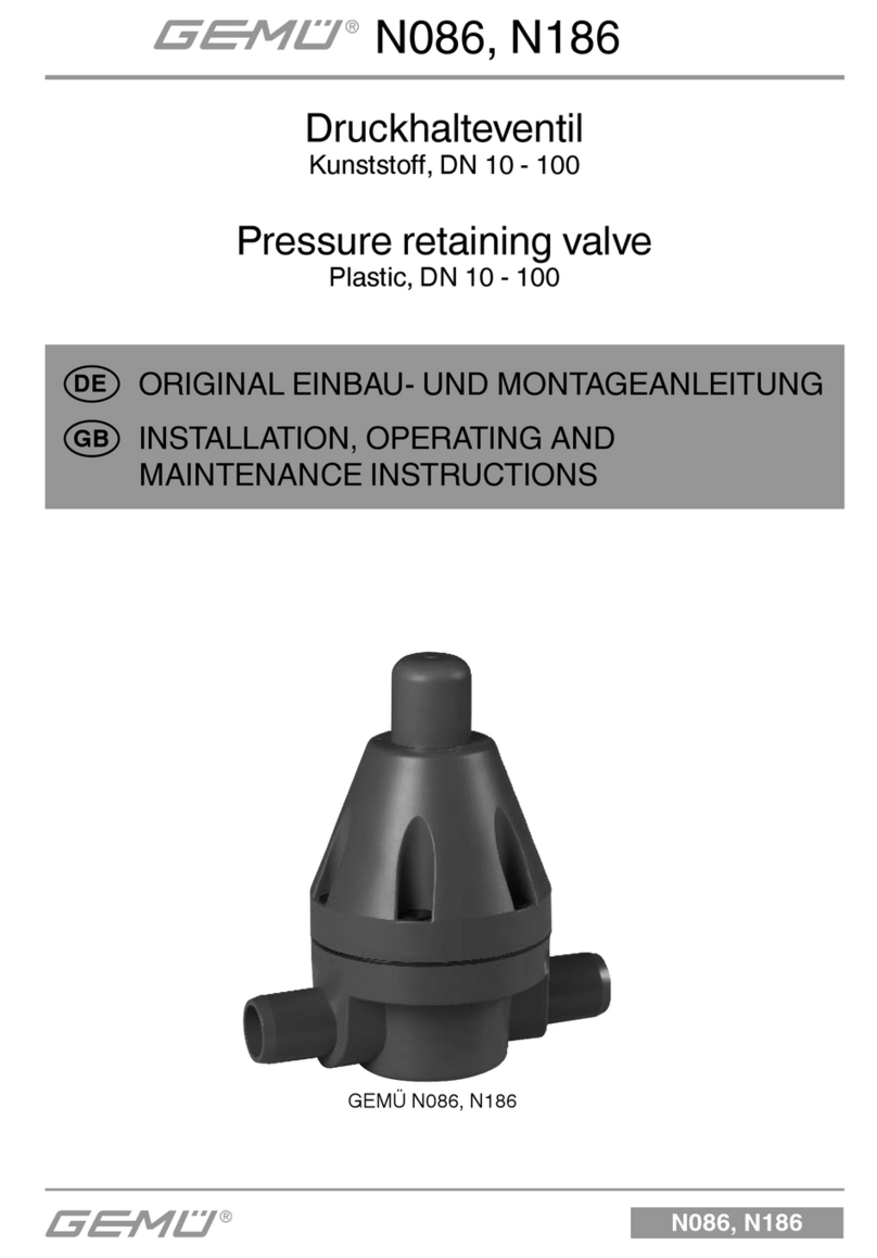
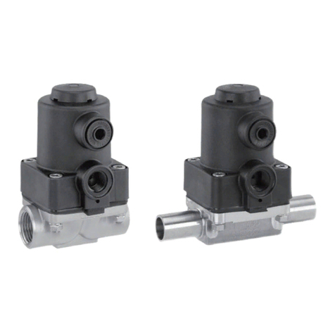
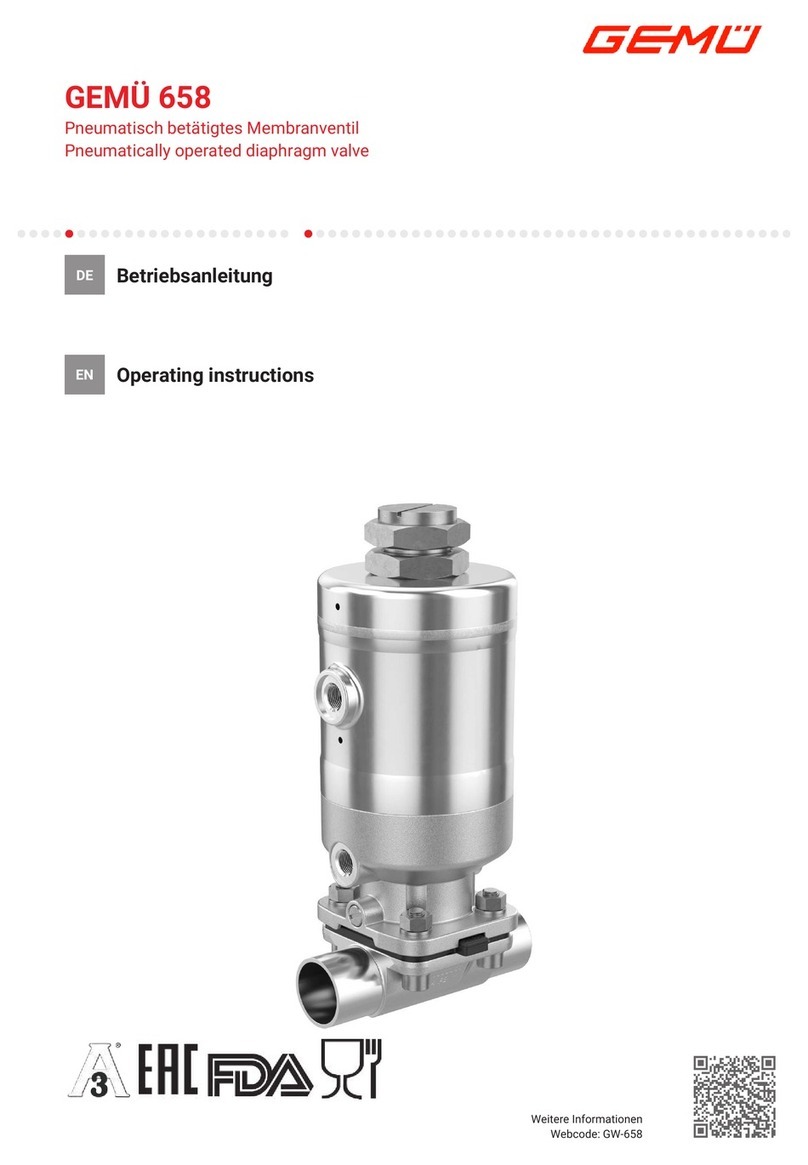
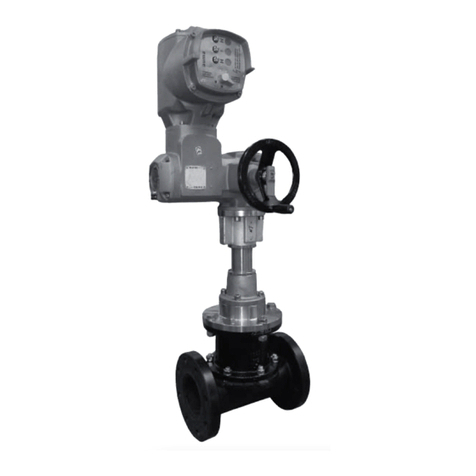
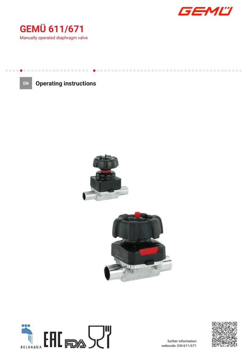
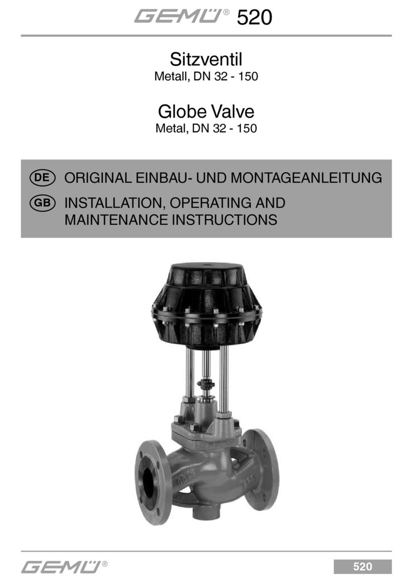
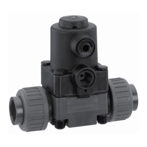
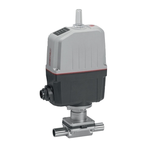
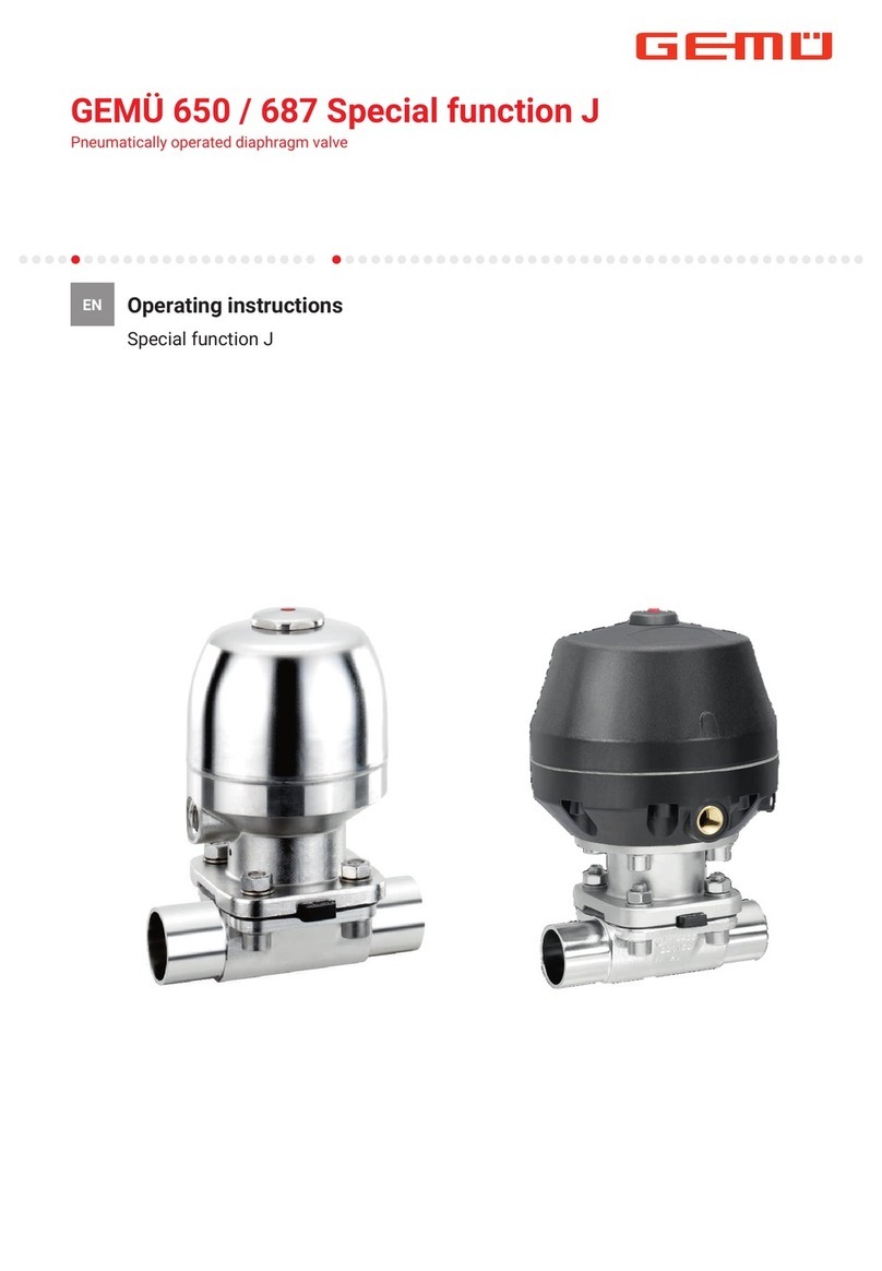
GEM 653 Assembly instructions

653, 654
653, 654
Diaphragm Valve
Metal, Diaphragm sizes 8 - 100
GB INSTALLATION, OPERATING AND
MAINTENANCE INSTRUCTIONS

653, 654 2 / 28
20 Troubleshooting /
Fault clearance 25
21 Sectional drawing
and spare parts 26
22 EC Declaration of Conformity 27
1 General information
Prerequisites to ensure that the GEMÜ valve
functions correctly:
Correct transport and storage
Installation and commissioning by trained
personnel
Operation according to these installation,
operating and maintenance instructions
Recommended maintenance
Correct installation, operation, servicing and
repair work ensure faultless valve operation.
The descriptions and instructions
apply to the standard versions.
For special versions not described
in these installation, operating
and maintenance instructions the
basic information contained herein
applies in combination with any
additional special documentation.
All rights including copyright
and industrial property rights are
expressly reserved.
2 General safety information
The safety information does not take into
account:
Unexpected incidents and events, which
may occur during installation, operation
and servicing.
Local safety regulations which must be
adhered to by the operator and by any
additional installation personnel.
Contents
1 General information 2
2 General safety information 2
2.1 Information for service and
operating personnel 2
2.2 Warning notes 3
2.3 Symbols used 3
3 Definition of terms 4
4 Intended area of use 4
5 Condition as supplied
to customer 4
6 Technical data 4
7 Order data 6
8 Manufacturer’s information 9
8.1 Transport 9
8.2 Delivery and performance 9
8.3 Storage 9
8.4 Tools required 9
9 Functional description 9
10 Construction 9
11 Installation and operation 10
11.1 Installing the diaphragm valve 10
11.2 Operation 11
11.3 Setting the seal adjuster
and the stroke limiter 12
12 Assembly / disassembly
of spare parts 15
12.1 Valve disassembly
(removing bonnet from body) 15
12.2 Removing the diaphragm 15
12.3 Mounting the diaphragm 15
12.3.1 General information 15
12.3.2 Mounting a concave diaphragm 18
12.3.3 Mounting a convex diaphragm 19
12.4 Bonnet mounting
on the valve body 19
13 Special versions 20
13.1 Special version with
electrical locking device 20
13.2 Special version with
mechanical locking device 20
13.3 Special version for mounting
of proximity switches 21
14 Commissioning 23
15 Inspection and servicing 23
16 Disassembly 24
17 Disposal 24
18 Returns 24
19 Information 24

3 / 28 653, 654
2.1 Information for service
and operating personnel
The installation, operating and maintenance
instructions contain fundamental safety
information that must be observed during
commissioning, operation and servicing.
Non-compliance with these instructions may
cause:
Personal hazard due to electrical,
mechanical and chemical effects.
Hazard to nearby equipment.
Failure of important functions.
Hazard to the environment due to the
leakage of dangerous materials.
Prior to commissioning:
GRead the installation, operating and
maintenance instructions.
GProvide adequate training for the
installation and operating personnel.
GEnsure that the contents of the
installation, operating and maintenance
instructions have been fully understood
by the responsible personnel.
GDefine the areas of responsibility.
During operation:
GKeep the installation, operating and
maintenance instructions available at the
place of use.
GObserve the safety information.
GUse only in accordance with the
specifications.
GAny servicing work and repairs not
described in the installation, operating
and maintenance instructions must not
be performed without consulting the
manufacturer first.
DANGER
Strictly observe the safety data sheets
or the safety regulations that are valid
for the media used.
In cases of uncertainty:
Consult the nearest GEMÜ sales office.
2.2 Warning notes
Wherever possible, warning notes are
organised according to the following
scheme:
SIGNAL WORD
Type and source of the danger
®Possible consequences of
non-observance.
GMeasures for avoiding danger.
Warning notes are always marked with a
signal word and sometimes also with a
symbol for the specific danger.
The following signal words and danger
levels are used:
DANGER
Imminent danger!
®Non-observance will lead to death or
severe injury.
WARNING
Potentially dangerous situation!
®Non-observance can cause death or
severe injury.
CAUTION
Potentially dangerous situation!
®Non-observance can cause moderate
to light injury.
CAUTION (WITHOUT SYMBOL)
Potentially dangerous situation!
®Non-observance can cause damage to
property.
2.3 Symbols used
Danger - hot surfaces!
Danger - corrosive materials!
Hand: indicates general information
and recommendations.

653, 654 4 / 28
GBullet point: indicates the tasks to
be performed.
®Arrow: indicates the response(s) to
tasks.
Enumeration sign
3 Definition of terms
Working medium
The medium that flows through the
diaphragm valve.
4 Intended area of use
The GEMÜ 653 or 654 diaphragm valve
is designed for installation in piping
systems. It controls a flowing medium by
manual operation.
The valve may only be used providing
the product technical criteria are
complied with (see chapter 6
"Technical data").
Do not paint the bolts and plastic parts of
the diaphragm valve!
WARNING
Use the diaphragm valve only for the
intended purpose!
®Otherwise the manufacturer liability and
guarantee will be void.
GUse the diaphragm valve only in
accordance with the operating
conditions specified in the contract
documentation and in the installation,
operating and maintenance
instructions.
GThe diaphragm valve may only be used
in potentially explosive zones confirmed
in the declaration of conformity (ATEX).
5 Condition as supplied
to customer
The GEMÜ diaphragm valve is supplied as a
separately packed component.
6 Technical data
Bonnet material
Bonnet A4 stainless steel
Cap (DN 10 - DN 40) PEEK
Cap (DN 50 - DN 100) PES
653 handwheel PPS glass filled
654 handwheel A4 stainless steel
Ambient conditions
Max. ambient temperature Standard 60 °C
Max. ambient temperature Accessory MAG 35 °C
Temperature at mounting point for proximity switches see
ambient temperature diagram below
Working medium
Corrosive, inert, gaseous and liquid media which have no
negative impact on the physical and chemical properties of
the body and diaphragm material.
Operating temperature max. 150 °C
(dependent on medium wetted materials)
The valve will seal in both flow directions up to full operating
pressure (all pressures are gauge pressures).
20 40 60 80 100 120 140 160
120
100
80
60
40
20
00
Medium temperature [°C]
Temperature at proximity switch [°C]
Values measured at 25 °C ambient temperature
Operating pressure [bar]
Diaphragm size EPDM/FPM PTFE
8 0 - 10 0 - 6
10 0 - 10 0 - 6
25 0 - 10 0 - 6
40 0 - 10 0 - 6
50 0 - 10 0 - 6
80 0 - 10 0 - 6
100 0 - 10 0 - 6
All pressures are gauge pressures. Operating pressure values were
determined with static operating pressure applied on one side of a
closed valve. Sealing at the valve seat and atmospheric sealing is
ensured for the given values. Information on operating pressures
applied on both sides and for high purity media on request.
Version with PTFE diaphragm up to 10 bar possible with bonnet
special function "H" and forged valve body.

5 / 28 653, 654
GEMÜ 654 - 0TN (MG 8)GEMÜ 654 - 0TH (MG 8)
GEMÜ 653 - T
(MG 10 - 100)
GEMÜ 654 - T
(MG 10 - 100)
GEMÜ 653 - D
(MG 10 - 50)
GEMÜ 654 - D
(MG 10 - 50)
Kv values [m³/h]
MG DN DIN
Code 0
DIN 11850
Series 1
Code 16
DIN 11850
Series 2
Code 17
DIN 11850
Series 3
Code 18
SMS 3008
Code 37
ASME BPE
Code 59
EN ISO
1127
Code 60
8
40.5------
6 1.1 - - - - - 1.2
8 1.3 - - - - 0.6 2.2
10 - 2.1 2.1 2.1 - 1.3 -
15 - - - - - 2.0 -
10
10 - 2.4 2.4 2.4 - 2.2 3.3
15 3.3 3.8 3.8 3.8 - 2.2 4.0
20 - - - - - 3.8 -
25
15 4.1 4.7 4.7 4.7 - - 7.4
20 6.3 7.0 7.0 7.0 - 4.4 13.2
25 13.9 15.0 15.0 15.0 12.6 12.2 16.2
40 32 25.3 27.0 27.0 27.0 26.2 - 30.0
40 29.3 30.9 30.9 30.9 30.2 29.5 32.8
50 50 46.5 48.4 48.4 48.4 51.7 50.6 55.2
80 65 - - 77.0 - 68.5 68.5 96.0
80 - - 111.0 - 80.0 87.0 111.0
100 100 - - 194.0 - 173.0 188.0 214.0
Kv values determined acc. to IEC 534 standard, inlet pressure 6 bar, Δp 1 bar, stainless steel valve body and soft elastomer diaphragm.
MG = diaphragm size
Diaphragm temperature range [°C]
Diaphragm Liquid Media Steam
(Sterilisation)Code
Min. Max.
EPDM -10 90 150 °C, max. 60 min 13/3A
EPDM -10 90 150 °C, max. 60 min 16/6A
EPDM -10 90 150 °C, max. 180 min 17
PTFE -10 90 Constant temperature* 150 °C 52/5A
PTFE -10 90 Constant temperature* 150 °C 5E
FPM -10 90 not applicable 4/4A
PTFE -10 90 150 °C, max. 40 min 5F
* The valves concerned must be serviced regulary if steam is applied continuously

6 / 28
653, 654
7 Order data
GEMÜ 653 - LOC GEMÜ 654 - MAG GEMÜ 653 - proximity switches
Body configuration Code
Tank valve body B**
2/2-way body D
Multi-port design M**
T body T*
* For dimensions see T Valves brochure
** Dimensions and versions on request
Bonnet size Code
Diaphragm size 8 0
Diaphragm size 10 1
Diaphragm size 25 2
Diaphragm size 40 3
Diaphragm size 50 4
Diaphragm size 80 5
Diaphragm size 100 6
Valve body material Code
1.4435 - BN2 (CF3M), investment casting Fe<0.5% 32
1.4435 (ASTM A 351 CF3M
≙316L
), investment casting 34
1.4408, investment casting 37
1.4408, PFA lined 39
1.4435 (316L), forged body 40
1.4435 (BN2), forged body Fe<0.5% 42
Control function Code
Manually operated 0
Bonnet version Code
For body configuration D
(diaphragm size 10 - 50) D
For body configurations B, D, M and T
(diaphragm size 8- 100) T
Bonnet for special function
for body configurations B, D, M and T
(diaphragm size 10 - 100) X
Flanges
Flanges EN 1092 / PN16 / form B,
length EN 558, series 1,
ISO 5752, basic series 1 8
Flanges ANSI CLASS 125/150 RF,
length MSS SP-88 38
Flanges ANSI CLASS 125/150 RF,
length EN 558, series 1,
ISO 5752, basic series 1 39
Clamp connections
Clamps ASME BPE for pipe ASME BPE,
length ASME BPE 80
Clamps DIN 32676 series B for pipe EN ISO 1127,
length EN 558, series 7 82
Clamps ASME BPE for pipe ASME BPE,
length EN 558, series 7 88
Clamps DIN 32676 series A for pipe DIN 11850,
length EN 558, series 7 8A
Clamps SMS 3017 for pipe SMS 3008,
length EN 558, series 7 8E
Aseptic clamps on request
For overview of available valve bodies see data sheet page 13
Connection Code
Butt weld spigots
Spigots DIN 0
Spigots DIN 11850, series 1 16
Spigots DIN 11850, series 2 17
Spigots DIN 11850, series 3 18
Spigots DIN 11866, series A 1A
Spigots DIN 11866, series B 1B
Spigots JIS-G 3447 35
Spigots JIS-G 3459 36
Spigots SMS 3008 37
Spigots BS 4825, part 1 55
Spigots ASME BPE 59
Spigots EN ISO 1127 60
Spigots ANSI/ASME B36.19M, Schedule 10s 63
Spigots ANSI/ASME B36.19M, Schedule 40s 65
Threaded connections
Threaded sockets DIN ISO 228 1
Threaded spigots DIN 11851 6
One side threaded spigot, other side
cone spigot and union nut, DIN 11851 62
Aseptic unions on request
Diaphragm material Code
FPM 4 4A*
EPDM 13 3A*
EPDM 16 6A*
EPDM 17 17*
PTFE/EPDM convex PTFE loose 5E**
PTFE/FPM convex PTFE loose 5F
PTFE/EPDM PTFE laminated 52 5A*
* for diaphragm size 8
** for use with valve bodies see data sheet page 13
Material complies with FDA requirements, except code 4 and 4A

7 / 28 653, 654
Bonnet function Code
With seal adjuster and stroke limiter (GEMÜ 653 diaphragm size 10 - 50) H
(GEMÜ 654 diaphragm size 8- 100)
Without seal adjuster and without stroke limiter (GEMÜ 653 diaphragm size 10 - 100) N
(GEMÜ 654 diaphragm size 8- 100)
With seal adjuster (diaphragm size 80 - 100) S
Special versions
With seal adjuster, stroke limiter and mounting for proximity switches M 8x1 (diaphragm size 10 - 50) A*
With seal adjuster and mounting for proximity switches M 12x1 (diaphragm size 80 - 100)
With seal adjuster, stroke limiter and locking device (both directions) and (diaphragm size 10 - 50) B*
mounting for proximity switches M 8x1
With seal adjuster, locking device (both directions) and (diaphragm size 80 - 100)
mounting for proximity switches M 12x1
With seal adjuster, stroke limiter and safety gland packing (diaphragm size 10 - 50) E*
With seal adjuster and safety gland packing (diaphragm size 80 - 100)
With seal adjuster, stroke limiter, locking device to prevent closing and (diaphragm size 10 - 50) F*
mounting for proximity switches M 8x1
With seal adjuster, locking device to prevent closing and (diaphragm size 80 - 100)
mounting for proximity switches M 12x1
With seal adjuster, stroke limiter, locking device to prevent opening and (diaphragm size 10 - 50) K*
mounting for proximity switches M 8x1
With seal adjuster, locking device to prevent opening and (diaphragm size 80 - 100)
mounting for proximity switches M 12x1
* only in connection with bonnet version X
* only in T-valve version
Order example 653 50 D 60 40 13 0 4 D H 1503
Type 653
Nominal size 50
Body configuration (code) D
Connection (code) 60
Valve body material (code) 40
Diaphragm material (code) 13
Control function (code) 0
Bonnet size (code) 4
Bonnet version (code) D
Bonnet function (code) H
Nominal size (mm)*
Connection (code)*
Surface finish (code) 1503
Valve body surface finish, internal contour
Forged body
Code 40, 42 Investment casting
Code 32, 34 Code
Ra ≤6.3 μm blasted internal/external - X 1500
-- electropolished - X 1509
Ra ≤0.8 μm mechanically polished internal, blasted external X X 1502
Ra ≤0.8 μm electropolished internal/external X - 1503
Ra ≤0.6 μm mechanically polished internal, blasted external X X 1507
Ra ≤0.6 μm electropolished internal/external X - 1508
Ra ≤0.4 μm mechanically polished internal, blasted external X - 1536
Ra ≤0.4 μm electropolished internal/external X - 1537
Ra ≤0.25 μm mechanically polished internal, blasted external X - 1527
Ra ≤0.25 μm electropolished internal/external X - 1516
Ra acc. to DIN 4768; at defined reference points
Surface finish data refer to medium wetted surfaces

653, 654 8 / 28
Special versions
See chapter 13 for a detailed description of special versions.
The solenoids, padlocks etc. for the "locking device" must be ordered separately as accessories.
Available only in connection with the bonnet additional functions B, K, F!
Type of accessory MAG - Electrical locking device
Control function 1 - Normally closed (locking device active)
Control function 2 - Normally open (locking device inactive)
Voltage / Frequency C1 - 24 V DC
Type of accessory LOC - Mechanical locking device
Control function B - without padlock
L - with padlock
EDP No. Designation Description
88264576 653MAGSV1 C1 AT
Electromagnetic locking device
24 V DC, normally closed, M22x1
ATEX
88232776 653MAGSV1 C1
Electromagnetic locking device
24 V DC, normally closed, M22x1
IP 54, connector socket design A DIN EN 175301-803
88279388 653MAGSV2 C1
Electromagnetic locking device
24 V DC, normally open, M22x1
IP 54, connector socket design A DIN EN 175301-803
88239348 653LOCSVL Locking device M22x1 with padlock
88239405 653LOCSVB Locking device M22x1 without padlock
Order example 653 MAG SV 1 C1
Type 653
Type of accessory MAG
Kit SV
Control function (code) 1
Voltage / Frequency (code) C1

9 / 28 653, 654
8 Manufacturer’s information
8.1 Transport
GOnly transport the diaphragm valve by
suitable means. Do not drop. Handle
carefully.
GDispose of packing material according
to relevant local or national disposal
regulations / environmental protection
laws.
8.2 Delivery and performance
GCheck that all parts are present and
check for any damage immediately upon
receipt.
GThe scope of delivery is apparent from
the dispatch documents and the design
from the order number.
GThe performance of the diaphragm valve
is checked at the factory.
8.3 Storage
GStore the diaphragm valve free from dust
and moisture in its original packaging.
GAvoid UV rays and direct sunlight.
GStore the diaphragm valve in "open"
position.
GMaximum storage temperature: 40 °C.
GSolvents, chemicals, acids, fuels or
similar fluids must not be stored in the
same room as valves and their spare
parts.
8.4 Tools required
GThe tools required for installation and
assembly are not included in the scope
of delivery. Only the setting tool for the
stroke limiter of GEMÜ 654 diaphragm
size 80 + 100 is included (see page 14).
GUse appropriate, functional and safe
tools.
9 Functional description
The metal diaphragm valve is equipped
with a stainless steel bonnet. GEMÜ 653
has a handwheel in high temperature and
chemically resistant plastic, GEMÜ 654 a
stainless steel handwheel.The handwheels
for diaphragm size 8 are rising, those for
diaphragm sizes 10-100 are non-rising. An
optical position indicator is standard.Two
bonnet versions are available: for 2/2-way
bodies and for T bodies or multi-port bodies.
The valve body and the diaphragm are
available in various designs as shown in
the data sheet.The diaphragm valve can
be continuously opened or closed.Various
special versions are described in these
installation, operating and maintenance
instructions.
10 Construction
!
Optical position
indicator
Handwheel
Diaphragm size 8
!
Optical position
indicator
Handwheel
Diaphragm size 10-100
Construction
1 Valve body
2 Diaphragm
A Bonnet

653, 654 10 / 28
11 Installation and operation
Prior to installation:
GEnsure that valve body and diaphragm
material are appropriate and compatible
to handle the working medium.
GCheck the suitability prior to the
installation.
See chapter 6 "Technical data".
11.1 Installing the
diaphragm valve
WARNING
The equipment is subject to pressure!
®Risk of severe injury or death!
GOnly work on depressurized plant.
WARNING
Corrosive chemicals!
®Risk of caustic burns!
GWear appropriate protective
gear when installing.
CAUTION
Hot plant components!
®Risk of burns!
GOnly work on plant that has
cooled down.
CAUTION
Never use the valve as a step or an aid
for climbing!
®This entails the risk of slipping-off or
damaging the valve.
CAUTION
Do not exceed the maximum
permissible pressure!
®Take precautionary measures to
avoid possible pressure surges
(water hammer).
GInstallation work must only be performed
by trained personnel.
GUse appropriate protective gear as
specified in plant operator's guidelines.
Installation location:
CAUTION
GDo not apply external force to the valve.
GChoose the installation location so that
the valve cannot be used as a foothold
(climbing aid).
GLay the pipeline so that the valve body
is protected against transverse and
bending forces, and also vibrations and
tension.
GOnly mount the valve between
matching aligned pipes.
Direction of the working medium:
optional.
Mounting position of the diaphragm valve:
optional.
Installation:
1. Ensure the suitability of the valve for
each respective use.The valve must
be appropriate for the piping system
operating conditions (medium, medium
concentration, temperature and
pressure) and the prevailing ambient
conditions. Check the technical data of
the valve and the materials.
2. Shut off plant or plant component.
3. Secure against recommissioning.
4. Depressurize the plant or plant
component.
5. Completely drain the plant (or plant
component) and let it cool down until
the temperature is below the media
vaporization temperature and scalding
can be ruled out.
6. Correctly decontaminate, rinse and
ventilate the plant or plant component.
Installation - Butt weld spigots:
1. Adhere to good welding practices!
2. Disassemble the bonnet with the
diaphragm before welding the valve body
into the pipeline (see chapter 12.1).
3. Allow butt weld spigots to cool down.
4. Reassemble the valve body and the
bonnet with diaphragm (see chapter
12.4).

11 / 28 653, 654
Installation - Clamp connections:
GWhen installing clamp connections,
insert a gasket between the body clamp
and the adjacent piping clamp and join
them using the appropriate clamp fitting.
The gasket and the clamp for clamp
connections are not included in the scope
of delivery.
Important:
Butt weld spigots /
clamp connections:
Angle of rotation for welding
into pipeline to enable optimised
draining see brochure "Angle of
rotation for 2/2-way valve bodies"
(on request or
www.gemu-group.com).
Installation - Threaded connections:
GScrew the threaded connections into the
piping in accordance with valid standards.
GScrew the diaphragm valve body into the
piping, use appropriate thread sealant.
The thread sealant is not included in the
scope of delivery.
Installation - Flange connection:
1. Pay attention to clean, undamaged
sealing surfaces on the mating flanges.
2. Align flanges carefully before installing
them.
3. Centre the seals accurately.
4. Connect the valve flange and the piping
flange using appropriate sealing material
and matching bolting. Sealing material
and bolts are not included in the scope
of delivery.
5. Use all flange holes.
6. Only use connector elements made of
approved materials!
7. Tighten the bolts diagonally!
Observe appropriate regulations for
connections!
After the installation:
GReactivate all safety and protective
devices.
11.2 Operation
CAUTION
Handwheel can become hot
during operation!
®Risk of burns!
GEnsure protective gloves
are worn when operating
handwheel.
Optical position indicator
Diaphragm size 8
Valve open Valve closed
Diaphragm sizes 10 - 100
Valve open Valve closed
Max. permissible operating torques:
Diaphragm size Nm
81
10 2
25 5
40 10
50 15
80 30
100 35

653, 654 12 / 28
11.3 Setting the seal adjuster
and the stroke limiter
Important:
Only set the seal adjuster and
stroke limiter when the valve
is completely assembled (with
diaphragm and valve body) and in
a cold condition!
GEMÜ 654 bonnet size 0TH
Diaphragm size 8
15
4
Greased
thread
9
3
10
Greased
O-rings
5
12
7
6
13
11
8
Setting the seal adjuster
GUnscrew locking screw 8and remove it.
GPull off handwheel 7.
GLoosen locking screw 9with a SW2 Allen
key (do not unscrew it completely).
GUnscrew stroke limiting sleeve 5and
remove it.
GLoosen lock nut 6with a SW19 open-end
wrench and unscrew it by 2 to 3 turns.
GTo deactivate the seal adjuster loosen the
seal adjuster nut 13 with a SW19 open-
end wrench unscrew it by 2 to 3 turns.
GPlace handwheel 7upside down on the
double flats of the threaded spindle 15.
Gently close the valve with handwheel 7
("CLOSED position") (valve is tight).
GScrew in the seal adjuster nut 13 until it
stops and secure with lock nut 6(SW19
open-end wrench).
Setting the stroke limiter
GMove the valve to the OPEN position by
turning handwheel 7(upside down) until
the required flow rate is reached.
GPull of handwheel 7from the threaded
spindle 15.
GScrew stroke limiting sleeve 5on until it
stops.
Important:
The threaded spindle 15 must
not turn during this process!
If necessary, hold with a SW8
open-end wrench!
GFix the stroke limiting sleeve 5with
locking screw 9(SW2 Allen key).
GPush handwheel 7into its original
position on the double flats of the
threaded spindle 15 and secure it with
locking screw 8.
Diaphragm sizes 10 - 50
Preparation for setting
GRemove protective cap a.
GMove the bonnet out of the end positions
to enable the handwheel to be turned in
both directions.
Releasing the stroke limiter
GTurn stroke limiter banticlockwise
upwards until the male thread is visible.

13 / 28 653, 654
Releasing the seal adjuster
GTurn seal adjuster cclockwise
downwards until it stops.
Setting the seal adjuster
GMove the bonnet to the desired CLOSED
position by turning the handwheel.
GTurn seal adjuster canticlockwise
upwards until it stops.
Setting the stroke limiter
GMove the bonnet to the desired OPEN
position by turning the handwheel.
GTurn stroke limiter bclockwise
downwards until it stops.
Important:
The seal adjuster must not turn
during this process.
Completing the settings
GPut protective cap ain place and align the
flats by a light twisting movement.
GPress protective cap adown.

653, 654 14 / 28
Diaphragm sizes 80 - 100
a
Preparation for setting
GRemove protective cap a.
GMove the bonnet out of the end positions
to enable the handwheel to be turned in
both directions.
b
Setting the stroke limiter
GTurn the stroke limiter anticlockwise
upwards using the supplied setting tool b
until the male thread is visible.
c
Releasing the seal adjuster
GTurn seal adjuster cclockwise
downwards until it stops.
Setting the seal adjuster
GMove the bonnet to the desired CLOSED
position by turning the handwheel.
c
GTurn seal adjuster canticlockwise
upwards until it stops.
GMove the bonnet to the desired OPEN
position by turning the handwheel.
b
GTurn the stroke limiter clockwise
downwards until it stops using the
supplied setting tool b.
Important:
The seal adjuster must not turn
during this process.

15 / 28 653, 654
a
Completing the settings
GPut protective cap ain place and align the
flats by a light twisting movement.
GPress protective cap adown.
12 Assembly / disassembly
of spare parts
18
19
19
20
2
A
1
12.1 Valve disassembly
(removing bonnet
from body)
1. Move bonnet Ato the open position.
2. Remove bonnet Afrom valve body 1.
3. Move bonnet Ato the closed position.
Important:
After disassembly, clean all parts
of contamination (do not damage
parts). Check parts for potential
damage, replace if necessary (only
use genuine parts from GEMÜ).
12.2 Removing the diaphragm
Important:
Before removing the diaphragm,
please remove the bonnet, see
"Valve disassembly (removing
bonnet from body)".
1. Unscrew the diaphragm or pull it out
(diaphragm size 8).
2. Clean all parts of the remains of product
and contamination. Do not scratch or
damage parts during cleaning!
3. Check all parts for potential damage.
4. Replace damaged parts (only use
genuine parts from GEMÜ).
12.3 Mounting the diaphragm
12.3.1 General information
Important:
Mount the correct diaphragm
that suits the valve (suitable for
medium, medium concentration,
temperature and pressure).The
diaphragm is a wearing part.
Check the technical condition and
function of the diaphragm valve
before commissioning and during
the whole term of use. Carry out
checks regularly and determine the
check intervals in accordance with
the conditions of use and / or the
regulatory codes and provisions
applicable for this application.

653, 654 16 / 28
Important:
If the diaphragm is not screwed
into the adapter far enough, the
closing force is transmitted directly
onto the diaphragm pin and not
via the compressor. This will cause
damage and early failure of the
diaphragm and thus leakage of the
valve. If the diaphragm is screwed
in too far no perfect sealing at the
valve seat will be achieved.The
function of the valve is no longer
ensured.
Important:
Incorrectly mounted diaphragm
may cause valve leakage /
emission of medium. In this case
remove the diaphragm, check the
complete valve and diaphragm and
reassemble again proceeding as
described above.
Diaphragm size 8:
The compressor is fixed to the spindle.
Compressor and bonnet flange seen from
below:
Diaphragm size 10:
The compressor is loose.
Compressor and bonnet flange seen from
below:
BD
C
DB
C
A
A
Pict. 1
Pict. 2
Anti-twist system of the spindle at the
compressor
A double flat (arrows picture 1) is fitted at
the end of the bonnet spindle to protect the
spindle against twisting. When mounting
the compressor, the double flat must be
in correct alignment with the recess of the
compressor back (arrows picture 2).
If the bonnet spindle is not in the correct
position, it must be turned to the correct
position.The position of Ais offset by 45° to
the position of C.
Place the compressor loosely on the bonnet
spindle, fit the recesses Dinto the guides C
and Ainto B.The compressor must be able
to be moved freely between the guides!

17 / 28 653, 654
Diaphragm sizes 25 - 80:
The compressor is loose.
Compressor and bonnet flange seen from
below:
D
D
B
B
C
C
A
A
If the bonnet spindle is not in the correct
position, it must be turned to the correct
position.The position of Ais offset by 45° to
the position of C.
Place the compressor loosely on the bonnet
spindle, fit the recesses Dinto the guides C
and Ainto B.The compressor must be able
to be moved freely between the guides!
Diaphragm size 100:
The diaphragm is round. Compressor and
bonnet flange seen from below:
C
D
D
C
B
B
A
A
Place the compressor loosely on the bonnet
spindle, fit Ainto Band Dinto C.

653, 654 18 / 28
12.3.2 Mounting a
concave diaphragm
Diaphragm size 8
Push-fit diaphragm:
CAUTION
Diaphragm may be damaged if the
compressor is wound down too far!
GTake care not to wind down the
compressor beyond the max. area
(see picture / grey arrows).
Tab
Fastening
spigot
Recess of compressor
1. Move bonnet Ato the closed position.
2. Place the diaphragm 2with the fastening
spigot in an inclined position at the
recess of the compressor.
3. Turn the diaphragm as manual force
is applied to push the spigot into the
compressor.
4. Align diaphragm tab (identifying
manufacturer and material) in parallel to
compressor weir.
Diaphragm sizes 10 - 100
Threaded pin type diaphragm:
Diaphragm boss
Recess of compressor
Diaphragm
pin
1. Move bonnet Ato the closed position.
2. Place the compressor loosely on the
bonnet spindle, fit Ainto Band D
into C (see chapter 12.3.1 "General
information").
3. Check if the compressor fits closely in
the guides.
4. Screw new diaphragm tightly into the
compressor manually.
5. Check if the diaphragm boss fits closely
in the recess of the compressor.
6. If it is difficult to screw it in, check the
thread, replace damaged parts (only use
genuine parts from GEMÜ).
7. When clear resistance is felt turn back
the diaphragm anticlockwise until its bolt
holes are in correct alignment with the
bolt holes of the bonnet.

19 / 28 653, 654
12.3.3 Mounting a
convex diaphragm
1. Move bonnet Ato the closed position.
2. Place the compressor loosely on the
bonnet spindle, fit Ainto Band D
into C (see chapter 12.3.1 "General
information").
3. Check if the compressor fits closely in
the guides.
4. Invert the new diaphragm face manually;
use a clean, padded mat with bigger
nominal sizes.
III.
I.
II.
Diaphragm face Diaphragm pin
5. Position the new backing diaphragm
onto the compressor.
6. Position the diaphragm face onto the
backing diaphragm.
7. Screw diaphragm face tightly into the
compressor manually.The diaphragm
boss must fit closely in the recess of the
compressor.
Diaphragm boss
Recess of compressor
Com-
pressor
Adapter
Backing
diaphragm
Diaphragm face
Diaphragm pin
8. If it is difficult to screw it in, check the
thread, replace damaged parts.
9. When clear resistance is felt turn back
the diaphragm anticlockwise until its bolt
holes are in correct alignment with the
bolt holes of the bonnet.
10. Press the diaphragm face tightly onto
the backing diaphragm manually so that
it returns to its original shape and fits
closely on the backing diaphragm.
12.4 Bonnet mounting
on the valve body
1. Move bonnet Ato the closed position.
2. Open bonnet Aapprox. 20 %.
3. Position bonnet Awith the mounted
diaphragm 2on the valve body 1, take
care to align the compressor weir and
valve body weir.
4. Tighten bolts 18, washers 19 and
nuts 20 by hand (hand tight only)
(fastening elements may vary dependent
on diaphragm size and / or valve body
version).
5. Fully tighten the bolts 18 with nuts 20
diagonally.
6. Ensure that the diaphragm 2 is
compressed evenly (approx. 10-15 %,
visible by an even bulge to the outside).
7. Check tightness of completely
assembled valve.
Important:
Service and maintenance:
Diaphragms degrade in the course
of time. After valve disassembly /
assembly check that the bolts and
nuts on the body are tight and
retighten as necessary (at the very
latest after the first sterilisation
process).

653, 654 20 / 28
13 Special versions
13.1 Special version with
electrical locking device
Special version of GEMÜ 653 / 654: the
locking device is actuated by a solenoid
(see figure below).
With additional functions B, K, F (types
of locking devices) the locking device is
electrically locked or unlocked (solenoid,
order data: MAG).
"Normally closed version (locking pin
extended)" in 24 V DC (see type key).
The locking device is also available with
ATEX approval.
13.2 Special version with
mechanical locking device
A special version of GEMÜ 653 / 654 is
available with a mechanical locking device.
With additional functions B, K, F (types of
locking device) the locking device can be
mechanically locked or unlocked (order
data: LOC).
The device is supplied with a padlock (L) or
without a padlock (B) (see type key).
Other manuals for 653
1
This manual suits for next models
1
Table of contents
Other GEM Control Unit manuals
Popular Control Unit manuals by other brands

Midland
Midland A-1076 Series Installation, operation & maintenance manual

Solinst
Solinst 464 Mk3 250 psi Replacement

FUTABA
FUTABA AH156AA manual

Apacer Technology
Apacer Technology EFC-D Series user manual

Acromag
Acromag VPX6600 user manual

Optical Systems Design
Optical Systems Design OSD361 Operator's manual

Panasonic
Panasonic SF-C13 instruction manual

Belkin
Belkin F1DE101H Quick installation guide

Elkron
Elkron MP 200 Installation and maintenance manual

Comunello
Comunello QUAD - 24V - 2M Installation and user manual

Festo
Festo CPX-FVDA-P2 Original instructions

Viessmann
Viessmann Vitovolt 200 Installation and service instructions