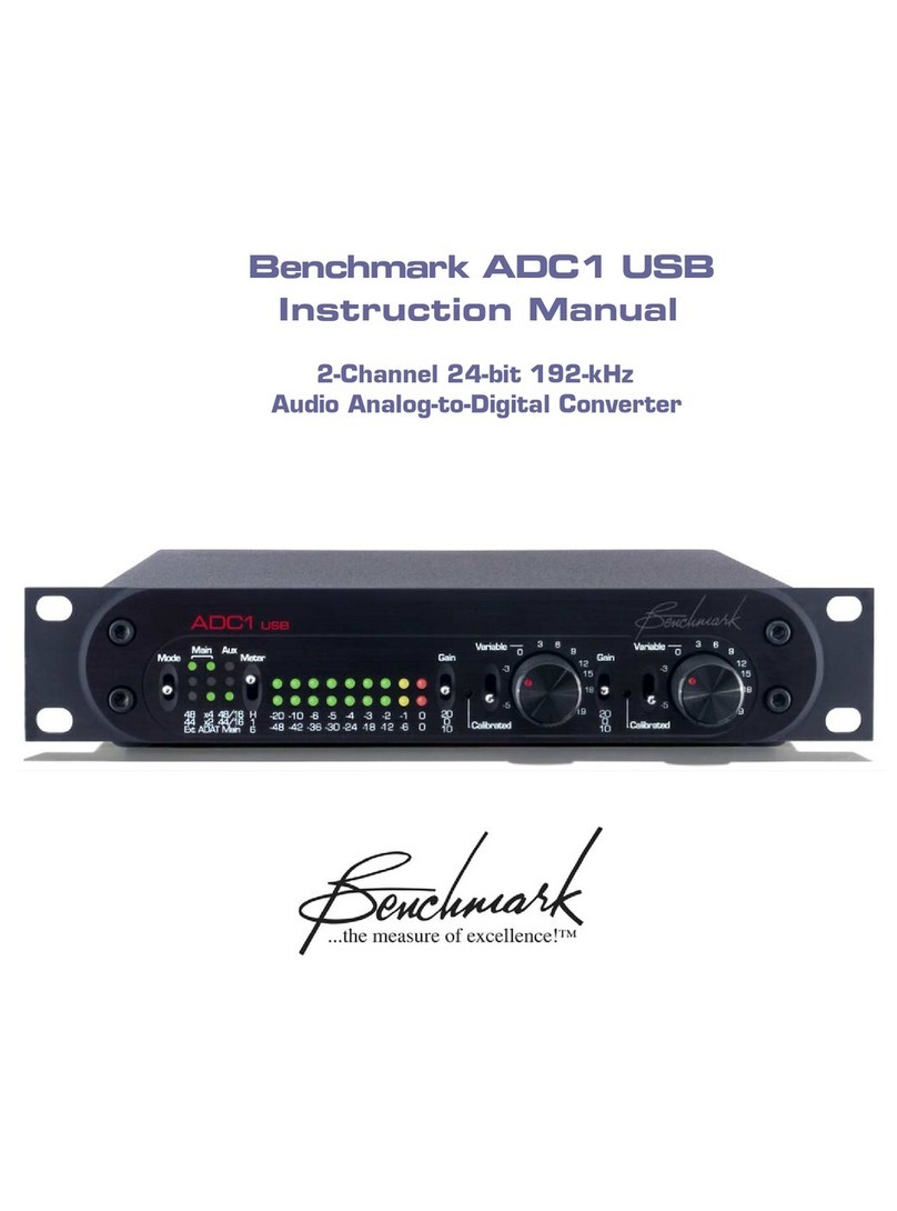
Benchmark ADC1 USB User manual

Benchmark ADC1 USB
Instruction Manual
2-Channel 24-bit 192-kHz
Audio Analog-to-Digital Converter

ADC1 USB Instruction Manual – Rev C Page 2
Contents
Overview 3
Features
Front Panel Descriptions 6
1) Mode Switch 6
2) Mode Display 7
3) Meter Switch 9
4) Meter Display 9
5) First-Stage Gai Switch 10
6) Seco d-Stage Gai Switch 10
7) Seco d-Stage Gai Dial 10
8) Seco d-Stage Calibratio Trimmer 10
Back Panel Descriptions 11
1) Bala ced A alog Li e I puts 12
2) Aux BNC Output 12
3) Mai BNC Output 12
4) TOSLINK Optical Output 13
5) AES/EBU XLR Output 13
6) Clock Refere ce I put 13
7) Word Clock Refere ce Output 14
8) Fuse Holder 14
9) AC Power E try Co ector 14
10) USB Computer I terface Output 14
Rack Mounting 1
Rack Mou t Coupler 15
Bla k Rack Pa el 15
Performance 16
Freque cy Respo se 16
I ter-Cha el Phase Respo se 17
THD+N vs. Level, 1 KHz 18
32K B-H FFT, Idle Cha el Noise 19
32K B-H FFT, -3 dBFS, 1 KHz 20
32K B-H FFT, -3 dBFS, 10 KHz 21
Specifications 22
A alog Audio I puts 22
Clock Refere ce I put 22
Word Clock Refere ce Output 22
Digital Audio Outputs 23
Audio Performa ce 24
Group Delay (Late cy) 25
LED Status I dicators 25
AC Power Requireme ts 26
Dime sio s 26
Weight 26
ADAT S/MUX 27
UltraLock™ … What Is It? 28
Regulatory Compliance 31
CE Certificate of Co formity 31
RoHS Complia ce 32
Warranty Information 32
1 Year Warra ty 32
Exte ded 5 Year Warra ty 32
Exte ded 2 Year I ter atio al Warra ty 33
Warra ty Repair Procedure 33

ADC1 USB Instruction Manual – Rev C Page 3
Overview
The ADC1 USB is a refere ce-quality, 2-
cha el, 192-kHz, 24-bit, a alog-to-digital
co verter featuri g Be chmark's Adva ced
USB Audio™ tech ology, phase-accurate
UltraLock™ clock system with multi-fu ctio
clock i put a d word clock output, a d
Be chmark’s 9-segme t dual-ra ge digital
LED meteri g. The ADC1 USB is desig ed for
maximum tra spare cy a d is well suited for
the most dema di g applicatio s i studios
a d masteri g facilities. A rugged a d
compact half-wide 1 RU e closure also makes
the ADC1 USB a excelle t choice for locatio
recordi g, broadcast facilities, a d mobile
rigs. The i ter al power supply supports all
i ter atio al voltages a d has ge erous
margi s for over a d u der voltage
co ditio s.
The ADC1 USB achieves outsta di g
performa ce over a wide ra ge of i put
levels. Each cha el has a 41-dete t variable
gai co trol, a 10-tur gai calibratio
trimmer, a d a 3-positio first-stage gai
switch (0, 10, a d 20 dB). The gai
calibratio co trols may be used to calibrate
the ADC1 USB to precise studio refere ce
levels. The variable gai co trols may be used
to optimize the gai -stagi g betwee a
micropho e preamplifier a d the ADC1 USB.
Both the pot a d the trimmer have a 24 dB
adjustme t ra ge. I combi atio with the
first-stage gai switch, these co trols provide
exceptio al SNR a d THD+N performa ce
over a 44 dB adjustme t ra ge. Each cha el
has a two-positio toggle switch that selects
betwee the variable a d calibrated gai
co trol.
The ADC1 USB has a total of 5 stereo digital
outputs (1 XLR, 2 coaxial, 1 optical a d 1
USB). The digital outputs ca operate
simulta eously at up to three i depe de t
sample rates. The auxiliary coaxial output
ca be co figured for 16-bit TPDF dithered
output. This u ique flexibility e ables
simulta eous recordi g to a CDR, a high-
resolutio digital recorder, a d a high
resolutio DAW. For example the CDR may
operate at 44.1/16, while the DAW operates
at 88.2/24, while the digital recorder operates
at 192/24. The optical output supports AES
or ADAT formats at resolutio s up to 192/24.
I ADAT mode, high sample rates are
supported usi g SMUX2 a d SMUX4. Backup
a d/or demo recordi gs ca be created with
ease while high-resolutio outputs are fed to
primary recordi g devices.
The ADC1 USB has a BNC Word Clock output
that follows the sample rate of the Mai
Outputs. Word Clock output is active i all
modes of operatio .
A multi-format clock-i put automatically
recog izes AES/EBU, SPDIF, Word Clock, or
Super Clock sig als. This clock i put is used
to sy chro ize the Mai Outputs. If desired,
the Mai Outputs may be drive from i ter al
sources. The ADC1 USB will automatically
revert to a i ter al clock source whe the
exter al clock is lost.
The ADC1 USB has two clock modes: Exter al
(Ext) a d I ter al. Both modes support 44.1,
48, 88.2, 96, 176.4 a d 192 kHz.
The Ext mode allows the ADC1 USB to lock to
a exter al clock refere ce. I Ext mode, the
ADC1 USB will follow cha ges i sample rate,
a d/or cha ges i the type of refere ce sig al
(AES, SPDIF, word clock, or super clock).
Whe a clock refere ce is ot available, the
i ter al mode must be used, a d a sample-
rate must be selected (44.1, 48, 88.2, 96,
176.4, or 192 kHz). Whe the I ter al mode
is active, the ADC1 USB is acti g as clock
master, operati g at the selected sample
rate, a d a y sig al at the clock refere ce
i put will be ig ored. If i ter al mode is used,
all devices co ected to the ADC1 USB digital
outputs will eed to be co figured to lock to
the ADC1 USB. The clock output o the back
of the ADC1 USB ca be used if the co ected
device(s) require word clock.
The Be chmark UltraLock™ system is 100%
jitter immu e. The A/D co versio clock is
totally isolated from the AES/EBU, SPDIF,
ADAT, WC, a d super clock i terfaces. This

ADC1 USB Instruction Manual – Rev C Page 4
topology outperforms two-stage PLL desig s.
I fact, o jitter-i duced artifacts ca be
detected usi g a Audio Precisio System 2
Cascade test set. Measureme t limits i clude
detectio of artifacts as low as -140 dBFS,
applicatio of jitter amplitudes as high as
12.75 u it i tervals (UI) a d applicatio of
jitter over a freque cy ra ge of 2 Hz to 200
kHz. A poor-quality refere ce clock will ot
degrade the jitter performa ce of the ADC1
USB. I additio , the AES/EBU receiver IC
used for AES clock refere ce has bee
selected for its ability to decode sig als i the
prese ce of very high levels of jitter. The
Be chmark UltraLock system delivers
co siste t performa ce u der all operati g
co ditio s.
The ADC1 USB is desig ed to perform
gracefully i the prese ce of errors a d
i terruptio s at the clock refere ce i put. The
ADC1 USB will eve lock to a AES/EBU
sig al that has its sample-rate bit status set
i correctly si ce the sample rate is
determi ed by measuri g the i comi g
sig al. Lack of sample-rate status bits or
i correctly set status bits will ot cause loss
of audio.
The ADC1 USB is phase-accurate betwee
cha els a d betwee other ADC1 boxes
whe locked to AES/EBU or word clock
refere ce sig als. The word clock output from
o e ADC1 USB may be co ected to the clock
i put o a other ADC1 USB to expa d the
umber of phase-accurate co versio
cha els.

ADC1 USB Instruction Manual – Rev C Page 5
Features
• Two cha els of a alog-to-digital co versio
• Two XLR bala ced a alog i puts providi g high-performa ce over a 44 dB ra ge
• -15 dBu to +29 dBu i put se sitivity ra ge (at 0 dBFS)
• First-stage gai switches (1 per cha el): 0 dB, 10 dB a d 20 dB
• 41-dete t variable gai co trols (1 per cha el) with a 24 dB gai ra ge
• 10-tur gai calibratio co trols (1 per cha el) with a 24 dB gai ra ge
• 9-segme t dual-ra ge digital LED meters
• Sample rate LED i dicators for ‘Mai ’ a d ‘Aux’ digital outputs
• Sample rate for USB output is determi ed by computer (D.A.W./software)
• Co versio at 44.1, 48, 88.2, 96, 176.4, a d 192 kHz
• USB output resolutio 24 bits at 44.1, 48, 88.2, or 96 kHz
• Versatile exter al a d i ter al clock modes
• Multifu ctio clock i put with auto-recog itio of AES, SPDIF, Word Clock, or Super Clock
• Word Clock output
• Total jitter immu ity with Be chmark’s, phase-accurate UltraLock™ tech ology
• Simulta eous output of up to three differe t sample rates
• Simulta eous dithered 16 a d 24-bit outputs
• Five digital outputs (1 XLR, 2 Coax, 1 Optical, 1 USB)
• AES/EBU, ADAT, a d ADAT S/MUX2, a d ADAT S/MUX4 output formats
• THD+N = -104 dB, 0.00063% @ -3 dBFS i put, SNR 121 dB A-weighted
• Reliable a d co siste t performa ce u der all operati g co ditio s
• I ter al 115 V, 230 V, 50-60 Hz i ter atio al power supply with very wide operati g ra ge
• Low radiatio toroidal power tra sformer sig ifica tly reduces hum a d li e i terfere ce
• Meets FCC Class B a d CE emissio s requireme ts

ADC1 USB Instruction Manual – Rev C Page 6
Front Panel Descriptions
1) Mode Switch
The Mode Switch is a o -locki g toggle
switch which co trols the co versio modes
of the ADC1 USB.
Mode Switch Operation
The ADC1 USB ca be programmed to
fu ctio i a variety of co versio modes,
i cludi g simulta eous multiple sample rates,
bit depths, a d output formats usi g i ter al
a d/or exter al clock sources.
The USB output sample rate is always
co trolled by the computer with which it is
operati g. This is typically set i the
recordi g software (DAW), but it is
sometimes set withi the audio-utility co trol
pa el of the operati g systems (e.g.
‘AudioMIDI Setup’ i Mac OS X).
The co versio modes of the other four
outputs (XLR, optical, mai coax, a d
auxiliary coax) are set with the Mode Switch
by usi g press-a d-release or press-a d-hold
actio s. These fu ctio s are described i the
“Co versio Mode Programmi g” sectio .
Conversion Mode Programming
• Press-a d-release the Mode Switch up
to cycle through the clock source a d
sample rate optio s for the Mai
Outputs.
• Press-a d-release the Mode Switch
dow to cycle through the sample rate
a d bit depth optio s for the Aux
Output.
• Press-a d-hold the Mode Switch dow
for approximately 3 seco ds to switch
the optical output mode betwee
AES/EBU a d ADAT.
• Press-a d-hold the Mode Switch up for
approximately 3 seco ds to reset the
ADC1 USB to Factory Default setti gs.
Factory Default Settings
The ADC1 USB ca be easily reset to factory
default setti gs by pressi g a d holdi g the
Mode Switch up for approximately 3 seco ds.
The factory default setti g sy cs the mai
a d aux outputs to the exter al clock a d
co figures the optical output i AES/EBU
format.

ADC1 USB Instruction Manual – Rev C Page
2) Mode Display
The Mode Display i dicates the clock source,
sample rate, Aux output mode, a d optical
mode (ADAT, etc).
The Mode Display i dicates the operati g
mode of the digital XLR, optical, a d coax
outputs. It does ot display the sample rate
of the USB output. The USB sample rate is
set withi the software of the host computer.
Output Programming
The Mai Outputs ca be set to operate at a
fixed sample rate usi g the i ter al clock
source or they ca be set to follow a d lock to
a exter al clock source.
The Aux Output ca be set to typical DAT or
CD-writer resolutio s (TPDF-dithered; 16-bit;
44.1 or 48 kHz), or it ca be set to mirror the
Mai Output (bit-for-bit).
The Optical Output ca be set to AES/EBU
mode or ADAT mode.
The USB Output is sy chro ized to the
computer host. The sample-rate is
determi ed by the recordi g software.
External Clock Source ocking
The ADC1 USB ca sy c to a variety of
exter al clock sources, i cludi g Word Clock,
Super Clock, AES, a d SPDIF. O ce the ADC1
USB is locked to the exter al clock, it will
sy chro ize the Mai Outputs (a d Aux if
selected) to the sample rate of the Ext Ref
I put (exter al refere ce clock).
The bottom left LED i the Mode Display is
the Ext I dicator. If the Ext LED is off, the
the ADC1 USB is set to operate at a fixed
sample rate usi g the i ter al clock source.
If this LED is illumi ated the the ADC1 USB
is locked to a exter al clock source. Whe
locked, the Mode Display will i dicate the
sample rate.
If the refere ce sample rate is cha ged, the
ADC1 USB will automatically switch sample
rates to match the cha ge i the refere ce
sample rate. If the Ext LED is flashi g, the
ADC1 USB is set to sy c to a exter al clock
source a d is locki g to that source. The
ADC1 USB should lock i less tha 5 seco ds.
If a lock does ’t occur withi a 5 seco d
wi dow, there may be a problem with the
exter al refere ce clock. If a sy c error
occurs, verify a secure co ectio is prese t
betwee the ADC1 USB a d the exter al clock
source. The ADC1 USB is very tolera t of
low-level low-quality refere ce sig als.
External Clock Source
Synchronization
• Press up repeatedly o the Mode
Switch a d cycle through the Mai
Output modes u til the lower left Ext
LED is either o or flashi g.
Fixed Sample-Rate Conversion
The ADC1 USB ca be programmed to
co vert at a fixed sample rate usi g a
i ter al clock source. The followi g sample
rate freque cies are available: 44.1, 48, 88.2,
96, 176.4, a d 192 kHz. The Ext Ref I put is
ig ored whe the i ter al clock source is
selected.
Off = I ter al Sy c
O = Locked to Exter al Sy c
Flashi g = Exter al Sy c is
Selected, Not Locked

ADC1 USB Instruction Manual – Rev C Page 8
Setting the Fixed Sample Rate on
the Main Outputs
• Press-a d-release the Mode Switch up
repeatedly to cycle through the
available sample rates. The four LED's
i the upper left of the Mode Display
i dicate the sample rate, as illustrated
i the diagrams below.
Black = Lit
White = Not Lit
Gray = Irrelevant
44.1kHz 48 kHz 88.2 kHz
96 kHz 176.4 kHz 192 kHz
Sample Rate Display
Main Output
Colum o e of the Mode Display has a ‘48’
LED a d a ‘44’ LED. These i dicate sample
rates of 48 kHz a d 44.1 kHz respectively.
Colum two has a ‘x4’ LED a d a ‘x2’ LED.
These i dicate 4x or 2x multipliers. Multiply
the sample rate show i colum o e by the
multiplier show i colum two. For example,
if the ‘44’ a d ‘x2’ LED's are o , the sample
rate is 88.2 kHz (44.1 x 2 = 88.2).
Aux Output
The Aux Output ca be programmed to mirror
the Mai Outputs (bit for bit), or it ca
provide a lower-resolutio copy of the
co verted sig al at a i depe de t sample
rate. Colum three of the Mode Display
displays the Aux Output mode setti g.
NOTE: The Aux Output setti g does ot affect
the Mai Outputs i a y way.
Aux Output Programming
Press-a d-release the Mode Switch repeatedly
to cycle through the Aux Output mode
setti gs. The right-ha d colum of LED’s i
the Mode Display i dicates the Aux Output
mode as illustrated i the followi g diagram:
Exact Copy of
Mai Outputs
(24 bit)
44.1 kHz
16 bit
Dithered
48 kHz
16 bit
Dithered
ADAT or AES/EBU Selection for
the Optical Output
The Optical Output (o e of the three Mai
Outputs) ca provide either AES/EBU or ADAT
format. The AES/EBU mode works with most
S/PDIF optical i puts.
Press a d hold the Mode Switch dow to
cha ge the Optical Output mode. The
bottom-ce ter LED i dicates the optical mode
as illustrated i the followi g diagram:
Off = AES/EBU o Optical
Output
O = ADAT o Optical Output
Whe ADAT is active, S/MUX is automatically
e abled at all 2X a d 4X sample rates (88.2
kHz, 96 kHz, 176.4 kHz, a d 192 kHz).

ADC1 USB Instruction Manual – Rev C Page 9
3) Meter Switch
The Meter Switch selects the scale a d mode
of the 9-segme t LED Meter Display.
Meter Scale and Peak Hold
Function Selection
• Set the Meter Switch to “H” (top) to
e able the Peak Hold fu ctio a d set
the scale to a 1 dB step.
• Set the Meter Switch to “1” (ce ter) to
disable the Peak Hold fu ctio a d set
the scale to 1 dB step.
• Set the Meter Switch to “6” (dow ) to
disable the Peak Hold fu ctio a d set
the scale to a 6 dB step.
4) Meter Display
The ADC1 USB is equipped with a multi-
fu ctio 9-segme t LED meter. The Meter
Switch selects either a 6 dB step or 1 dB step
scale a d co trols the peak-hold fu ctio .
Meteri g is fully digital a d post-co versio
for absolute accuracy. The u its are dBFS (dB
below the level of a full-scale si e wave, or
more simply, dB below digital clip).
Time co sta ts are built i to the meters so all
tra sie t peaks ca be observed easily. If a
tra sie t peak has a duratio as short as o e
digital sample, a LED will be illumi ated a d
remai illumi ated lo g e ough to be
observed by the huma eye.
A peak i dicatio mimics the actio of the
eedle o a peak-readi g a alog meter, while
the remai i g LED's will follow the
i sta ta eous level of the audio.
The red 0 LED i dicates that a full-scale
digital code has bee reached a d that digital
clippi g has occurred. Full-scale eve ts as
short as o e digital sample, will light the 0
LED. Short si gle-sample digital clippi g
eve ts are ofte audible, a d all 0 dBFS
eve ts should be avoided.
The ADC1 USB has a very large dy amic
ra ge (especially whe operati g at 24-bit
output word le gths). It is wise to use some
of this dy amic ra ge to provide more
headroom as i sura ce agai st clippi g.
Leave some extra headroom betwee your
highest a ticipated peak a d the red 0 dBFS
LED.
Input Gain Adjustment
Each cha el o the ADC1 USB is equipped
with a 3-positio first-stage gai switch. The
first gai -stage provides exceptio al oise
performa ce at gai s of 0 dB, +10 dB, or +20
dB. This stage is followed by a seco d-stage
havi g a co ti uously variable gai ra ge of
-5 dB to +19 dB. This gai structure provides
ultra-high performa ce at a y gai setti g
betwee -5 dB a d +39 dB. The higher gai
setti gs will allow direct co ectio s from
ma y electro ic i strume ts a d i strume ts
with pickups ( o DI box required).
At a gai setti g of 0 dB, the co verter will
reach full-scale (0 dBFS) with a +24 dBu
i put level. The calibrated gai trim-pots are
factory calibrated for 0 dB seco d-stage gai .

ADC1 USB Instruction Manual – Rev C Page 10
) First-Stage Gain Switch
Input Gain Stages
The First-Stage Gai Switches ca apply
a alog gai (0, 10, or 20 dB) to the left
a d/or right cha el. Both cha els have
their ow dedicated switches. The First-Stage
Gai ca be used i ‘Calibrated’ or ‘Variable’
mode.
To select the first-stage gain
• Set the switch to “0” (ce ter) to select
0 dB (u ity) gai for the first-stage.
• Set the switch to “10” (dow ) to select
10 dB gai for the first-stage.
• Set the switch to “20” (up) to select 20
dB gai for the first-stage.
6) Second-Stage Gain Switch
The Seco d-Stage Gai Switch determi es
the type of seco d-stage gai co trol. The
switches (o e for each cha el) ca be set to
either ‘Variable’ or ‘Calibrated’. Whe the
switch is set to ‘Variable’, the seco d-stage
gai for that respective cha el is determi ed
by the Seco d-Stage Gai K ob. Co versely,
whe the switch is set to ‘Calibrated’, the
Seco d-Stage Calibratio Trimmer adjusts the
gai for fi ely-tu ed, calibrated operatio .
7) Second-Stage Gain Dial
The Seco d-Stage Gai Dial is a 41-dete t
gai co trol with a usable ra ge of
approximately -5 dB to +19 dB. I order to
use this gai co trol for a cha el, that
cha el’s respective Seco d-Stage Gai
Switch must be set to Variable (up).
8) Second-Stage Calibration
Trimmer
The Seco d-Stage Calibratio Trimmers are
10-tur gai trim pots with a useable ra ge of
approximately -5 dB to +19 dB. I order to
use the trim pots the Seco d-Stage Gai
Switch must be set to Calibrated (dow ).

ADC1 USB Instruction Manual – Rev C Page 11
Back Panel Descriptions
Digital Outputs
• (#5 above) XLR, 110-Ω, bala ced,
AES/EBU professio al format, 24-bits
• (#3) Mai BNC, 75-Ω, u -bala ced,
AES/EBU professio al format, 24-bit
compatible with most SPDIF i puts
• (#4) Optical TOSLINK, multi-format
(AES professio al, ADAT, ADAT S/MUX
II & IV), 24-bits
• (#10) USB Computer I terface
• (#2) Aux BNC, 75-Ω, u -bala ced,
AES/EBU professio al format, 24-bit or
16-bit, compatible with most SPDIF
i puts
The Mai a d Aux outputs are co trolled by
the fro t-pa el Mode Switch. The status of
these outputs is show i the Mode Display
adjace t to the Mode Switch.
The Mai Outputs always operate at 24-bits.
The coaxial, optical, a d XLR Mai Outputs
may be sy chro ized to a exter al clock
refere ce or may be co trolled by the i ter al
clock. The USB Mai Output is always
sy chro ized to the host (computer). The
Optical Output has two modes of operatio ;
AES/EBU a d ADAT. The ADAT mode supports
ADAT (44.1 a d 48 kHz), ADAT S/MUX
2
(88.2
a d 96 kHz), a d ADAT S/MUX
4
(176.4 a d
192 kHz).
The Aux Output ca operate asy chro ously
at 44.1 or 48 kHz with a TPDF-dithered 16-bit
word le gth. The Aux Output is provided as a
co ve ie ce for maki g safety backups or
demo recordi gs to low-resolutio 16-bit
recorders (i.e. CDR or DAT). If this low-
resolutio fu ctio is ot eeded, the Aux
Output ca be set to mirror the high-
resolutio Mai Outputs.

ADC1 USB Instruction Manual – Rev C Page 12
1) Balanced Analog Line Inputs
‘Left’ a d ‘Right’ bala ced i puts use locki g
Neutrik™ gold-pi female XLR jacks. These
i puts have a wide operati g ra ge. The i put
se sitivity (at 0 dBFS) ra ges from -15 dBu
(at maximum gai ) to +29 dBu (at mi imum
gai ). The i put impeda ce is 200k Ohms
bala ced, a d 100k Ohms u bala ced. The
high impeda ce a d se sitivity allow direct
co ectio s from ma y musical i strume ts
(adapter cable required). Direct co ectio of
piezo pickups is ot recomme ded as these
pickups require higher i put impeda ces (to
preve t low-freque cy roll-off problems).
• XLR pi 2 = + Audio I
• XLR pi 3 = - Audio I
• XLR pi 1 = Cable Shield (grou ded
directly to the chassis to preve t
i ter al grou d loops)
Unbalanced Source Adaptation
1. Co ect “+” or hot (tip o ¼ pho e plug,
ce ter pi o RCA plug) to XLR pi 2.
2. Co ect grou d (sleeve o ¼” pho e
plug, case o RCA plug) to XLR pi s 3 a d
1.
NOTE: It’s best to used bala ced wiri g (“+”,
“-“, “shield”) a d to tie the “-“a d “shield” at
the u bala ced co ector (source).
2) Aux BNC Output
The Aux Output (BNC) has a u ique feature
that allows it to output at a sample-rate a d
bit-depth that is i depe de t from the Mai
Output. Regardless of the sample-rate of the
Mai Output, the Aux output ca co vert at
44.1 or 48-kHz, 16-bit (TPDF dithered), for
simulta eous use with backup recordi g
devices (CDR, DAT, etc). The Aux Output ca
also be co figured to operate as a additio al
Mai Output with ide tical data as other Mai
digital outputs.
• Data Format = AES/EBU professio al
• Word Le gth = 16 bits TPDF dithered,
or 24 bits
• Sample Rate = 44.1 or 48 at 16 bits;
44.1, 48, 88.2, 96, 176.4, or 192 kHz
at 24-bits
• Clock Source = I ter al at 16 bits,
i ter al or exter al at 24 bits
3) Main BNC Output
The digital data output from the Mai BNC
Output is ide tical to that of the Mai XLR
Digital Output.
• Data Format = AES/EBU professio al
• Word Le gth = 24 bits
• Sample Rate = 44.1, 48, 88.2, 96,
176.4, or 192 kHz
• Clock Source = I ter al or exter al
BNC Main and Aux Outputs
The two BNC coaxial digital outputs use
female BNC co ectors. These co ectors are
securely mou ted directly to the rear pa el.
These are 1 Vpp u bala ced outputs with 75-
Ω source impeda ces. Outputs are DC-
isolated, tra sformer-coupled, curre t-
limited, a d diode-protected. 75-Ω coaxial
cables should be used whe co ecti g these
outputs to other devices. The use of 50-Ω
coax is ot recomme ded a d may cause
data tra smissio errors.
Co sumer-style, SPDIF RCA digital i terfaces
are commo o recordi g devices. The ADC1
USB ships with BNC-to-RCA adapters to allow
easy i terfaci g with co sumer-style digital
i terfaces. BNC to RCA coaxial cables are also
available from Be chmark.
BNC co ectors are specified by the AES3-id
a d SMPTE 276M sta dards for 75-Ω 1 Vpp
digital audio sig als a d are commo ly used
i video productio facilities a d other
professio al audio applicatio s. RCA
co ectors are specified by IEC 609588-3 for
75-Ω 0.5 Vpp co sumer-format digital audio
sig als (commo ly k ow as SPDIF). We
have chose to comply with the professio al
sta dards because the BNC co ectors lock
a d are ge erally more reliable tha RCA
co ectors. Complia ce with the 1 Vpp digital
audio sta dards i creases the reliability of
digital co ectio s, a d ofte allows
i creased tra smissio dista ces.

ADC1 USB Instruction Manual – Rev C Page 13
4) TOSLINK Optical Output
The Optical Output has four modes of
operatio ; AES/EBU, ADAT, ADAT S/MUX
2
,
a d ADAT S/MUX
4
. The AES/EBU mode is
compatible with most SPDIF optical i puts.
The ADAT LED o the fro t pa el is
illumi ated whe ever a y of the ADAT Modes
are active. S/MUX
2
a d S/MUX
4
are
automatically e abled if required to support
the selected sample rate. S/MUX
2
is active at
88.2 or 96 kHz, S/MUX
4
is active at 176.4 or
192 kHz.
The Optical Output uses what is ofte called a
TOSLINK, Type FO5, or 5 mm optical
co ector. The ADC1 USB uses a special high-
ba dwidth versio that supports AES/EBU
digital audio at sample rates up to 192 kHz.
Please ote that ma y optical i puts ca ot
support AES/EBU or SPDIF digital audio at
sample rates above 48 kHz, others are limited
to 96 kHz. A few products (such as the
Be chmark DAC1) support 192 kHz optical
i puts. Please ote that high-ba dwidth
optical tra smitters a d receivers are ot
required for ADAT, ADAT S/MUX
2
, or eve
ADAT S/MUX
4
.
AES/EBU Optical Output Mode
• Data Format = AES/EBU professio al
• Word Le gth = 24 bits
• Sample Rate = 44.1, 48, 88.2, 96,
176.4, or 192 kHz
• Clock Source = I ter al or exter al
ADAT Optical Output Mode
• Data Format = ADAT
• Word Le gth = 24 bits
• Sample Rate = 44.1 or 48 kHz
• Clock Source = I ter al or exter al
• ADAT cha el assig me ts: 1 = Left,
2 = Right, 3-8 = muted
ADAT S/MUX
2
Optical Output
Mode
• Data Format = ADAT
• Word Le gth = 24 bits
• Sample Rate = 88.2 or 96 kHz
• Clock Source = I ter al or exter al
• ADAT cha el assig me ts *: 1 = Left
a, 2 = Left b, 3 = Right a, 4 = Right b,
5-8 = muted
• * a, a d b are successive samples
ADAT S/MUX
4
Optical Output
Mode
• Data Format = ADAT
• Word Le gth = 24 bits
• Sample Rate = 176.4 or 192 kHz
• Clock Source = I ter al or exter al
• ADAT cha el assig me ts **: 1 =
Left a, 2 = Left b, 3 = Left c, 4 = Left
d, 5 = Right a, 6 = Right b, 7 = Right
c, 8 = Right d
• ** a, b, c, a d d are successive
samples
) AES/EBU XLR Output
The bala ced AES/EBU XLR output uses a
gold-pi Neutrik™ male XLR co ector. It
has a output impeda ce of 110-Ω as well as
DC-isolatio , tra sformer-coupli g, curre t-
limiti g, a d diode-protectio . It’s desig ed
to drive sta dard 4 Vpp AES sig als i to a
110-Ω load. 110-Ω digital cables are
recomme ded whe co ecti g this output to
other devices because a alog audio cables
may cause data tra smissio errors.
• Data Format = AES/EBU professio al
• Word Le gth = 24 bits
• Sample Rate = 44.1, 48, 88.2, 96,
176.4, or 192 kHz
• Clock Source = I ter al or exter al
6) Clock Reference Input
The Clock Refere ce I put auto-detects
AES/EBU, SPDIF, Word Clock, or Super Clock
sig als, a d automatically follows cha ges i
sample-rate. Whe Ext mode is active the
ADC1 USB will lock to the exter al clock
source. Be chmark’s UltraLock™ circuitry
isolates the co versio clock from a y jitter
prese t o the clock refere ce. Ext Mode will
ot degrade the co versio quality of the
ADC1 USB eve whe very high levels of
jitter are prese t o the clock refere ce.

ADC1 USB Instruction Manual – Rev C Page 14
7) Word Clock Reference
Output
This output provides a Word Clock sig al
which ca be passed to dow stream
compo e ts.
8) Fuse Holder
The fuse holder is built i to a drawer ext to
the IEC power co ector. The drawer
requires two 5 x 20 mm 250 V Slo-Blo
®
Type
fuses. The drawer i cludes a voltage
selectio switch with two setti gs: 110 a d
220. The fuse rati g for all voltage setti gs is
0.50 Amps.
The AC i put has a very wide i put voltage
ra ge a d ca operate over a freque cy
ra ge of 50 to 60 Hz. At 110, the ADC1 USB
will operate ormally over a ra ge of 90 to
140 VAC. At 220, the DAC1 USB will operate
ormally over a ra ge of 175 to 285 VAC.
Caution: Always i stall the correct fuses.
Always i sure that the voltage setti g is
correct for your locality.
9) AC Power Entry Connector
The AC power i put uses a sta dard IEC type
co ector. Withi the USA a d Ca ada, the
ADC1 USB ships with a power cord. I other
locatio s, a locatio -specific IEC style power
cord may be purchased from a local source
(i cludi g a local Be chmark dealer).
10) USB Computer Interface
Output
The USB output supports 44.1, 48, 88.2 a d
96 kHz sample rates at 24-bits.
The sample rate of the USB output is
i depe de t from the sample rate of the
other outputs o the ADC1 USB. For
example, the USB output ca operate at 96
kHz while the mai output is operati g a d
192 kHz a d the auxiliary output is operati g
at 44.1 kHz. All three outputs are fully
i depe de t, a d all are equipped with
Be chmark’s UltraLock™ jitter-atte uatio
system.
The USB output always acts as a slave. The
sample rate of the USB output is always
co trolled by the computer. The USB ca ot
be sy chro ized to the Ext Ref I . The USB
receives all of its sy chro izatio sig als
through the USB port. Be chmark’s
UltraLock™ system i sures that the audio
data is free from a y jitter-i duced artifacts.
Performa ce through the USB port matches
the performa ce through the other digital
outputs.
The USB jack o the ADC1 USB accepts a ‘B-
type’ male USB 1.1 or USB 2.0 co ector. A
‘A-B type’ USB cable is provided with the
ADC1 USB. The USB cable co ects the
ADC1 USB directly to a computer’s USB
output. The USB i terface utilizes USB 1.1
protocol, a d is compatible with both USB 1.1
a d USB 2.0 ports.
The USB i terface commu icates to the host
computer as a ‘ ative’ USB audio device a d,
therefore, does ot require the i stallatio of
a y custom drivers. Be chmark’s Adva ced
USB Audio tech ology achieves bit-
tra spare t operatio without o - ative
drivers.
The Be chmark USB i terface is truly a plug-
a d-play solutio . The ADC1 USB ca begi
streami g high resolutio audio bit-
tra spare tly withi seco ds after bei g
plugged i to a computer for the first time.
The ADC1 USB is desig ed, tested a d prove
compatible with the followi g four operati g
systems:
• Wi dows Vista
• Wi dows XP
• Wi dows 2000
• Mac OS X

ADC1 USB Instruction Manual – Rev C Page 15
Rack Mountin
The ADC1 USB is part of Be chmark’s ½-wide
System1™ product family. Each is o e rack
u it high a d is exactly ½ the width of a
sta dard 19” rack pa el. The fro t pa els o
System1™ products have rack-mou t holes
that are machi ed to co form to sta dard
rack-mou t dime sio s. Two ½-wide
System1™ u its may be joi ed together to
form a si gle rigid 19” pa el that ca be
i stalled i a y sta dard 19” rack.
Either ear of a ½-wide System1™ device ca
be mou ted directly to a sta dard 19” rack.
A Rack Mou t Coupler co ects the other ear
to a ½-wide Bla k Rack Pa el or a other ½-
width System1™ product
Tip: Use the rack-mou t screws supplied with
the DAC1 USB (or screws with plastic
washers) to avoid scratchi g the surface of
the faceplate.
The Rack Mou t Coupler a d Bla k Rack
Pa el are available from Be chmark.
Call us, visit our website:
http://www.be chmarkmedia.com or co tact
your dealer to purchase these accessories.
Rack Mount Coupler
The Rack Mou t Coupler is a machi ed
alumi um ju ctio block that joi s a y two
½-wide System1™ devices for rack mou ti g.
It is also used to joi a Blank Rack Panel to
a si gle ½-wide System1™ device.
Blank Rack Panel
The Bla k Rack Pa el is a ½-wide 1-RU
alumi um pa el for mou ti g a si gle ½-wide
System1™ device i a sta dard 19” rack.
I stallatio requires o e Rack Mou t Coupler.

ADC1 USB Instruction Manual Page 16
Performance
Frequency Response
The above graphs show the freque cy respo se of the ADC1 USB whe it is operati g at a 192-kHz
sample rate. Note that the amplitude respo se is dow by less tha 0.05 dB at 10 Hz a d 80 kHz.
The bass respo se exte ds well below the 10-Hz limitatio of the measureme t equipme t, a d
the high-freque cy a alog respo se exte ds well above the 96 kHz ba dwidth of 192 kHz digital
audio.

ADC1 USB Instruction Manual Page 1
Inter-Channel Phase Response
This graph shows that the differe tial phase is sig ifica tly better tha ± 0.25º from 10 Hz to 20
kHz.

ADC1 USB Instruction Manual Page 18
THD+N vs. Level, 1 KHz
w/20 kHz LPF unweighted
Below –4 dBFS, distortio is lower tha the oise floor of the co verter. Above –3 dBFS, distortio
reaches a maximum value of o ly –107 dBFS.

ADC1 USB Instruction Manual Page 19
32K B-H FFT, Idle Channel Noise
The above graph demo strates that the ADC1 USB is free from idle to es a d clock crosstalk. The
highest spurious to e measures –128 dBFS a d is AC li e related hum. The highest o -li e
related to e measures –135 dBFS.

ADC1 USB Instruction Manual Page 20
32K B-H FFT, -3 dBFS, 1 KHz
The above FFT plot shows that the ADC1 USB has very little harmo ic distortio . Distortio is
exceptio ally low a d is domi ated by 2
d
harmo ic distortio . Note the ear abse ce of spurious
to es.
Other manuals for ADC1 USB
2
Table of contents
Other Benchmark Media Converter manuals
Benchmark
Benchmark DAC1 USB User manual
Benchmark
Benchmark DAC3 DX User manual
Benchmark
Benchmark DAC2 DX User manual
Benchmark
Benchmark DAC3 B User manual
Benchmark
Benchmark DAC1 PRE User manual
Benchmark
Benchmark ADC1 USB User manual
Benchmark
Benchmark AD2402-96 User manual

Benchmark
Benchmark DAC2 DX User manual
Benchmark
Benchmark ADC1 USB User manual
Benchmark
Benchmark ADC16 User manual

