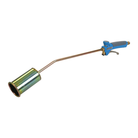
EWM PHW 100 User manual

Operating instructions
EN
welding torch
PHW 100
099-008232-EW501
Observe additional system documents!
26.05.2020

General instructions
WARNING
Read the operating instructions!
The operating instructions provide an introduction to the safe use of the products.
• Read and observe the operating instructions for all system components, especially the sa-
fety instructions and warning notices!
• Observe the accident prevention regulations and any regional regulations!
• The operating instructions must be kept at the location where the machine is operated.
• Safety and warning labels on the machine indicate any possible risks.
Keep these labels clean and legible at all times.
• The machine has been constructed to state-of-the-art standards in line with any applicable
regulations and industrial standards. Only trained personnel may operate, service and re-
pair the machine.
• Technical changes due to further development in machine technology may lead to a dif-
fering welding behaviour.
In the event of queries on installation, commissioning, operation or special conditions at the
installation site, or on usage, please contact your sales partner or our customer service
department on +49 2680 181-0.
A list of authorised sales partners can be found at www.ewm-group.com/en/specialist-dealers.
Liability relating to the operation of this equipment is restricted solely to the function of the equipment. No
other form of liability, regardless of type, shall be accepted. This exclusion of liability shall be deemed ac-
cepted by the user on commissioning the equipment.
The manufacturer is unable to monitor whether or not these instructions or the conditions and methods
are observed during installation, operation, usage and maintenance of the equipment.
An incorrectly performed installation can result in material damage and injure persons as a result. For this
reason, we do not accept any responsibility or liability for losses, damages or costs arising from incorrect
installation, improper operation or incorrect usage and maintenance or any actions connected to this in
any way.
© EWM AG
Dr. Günter-Henle-Strasse 8
56271 Mündersbach Germany
Tel.: +49 2680 181-0, Fax: -244
Email: [email protected]
www.ewm-group.com
The copyright to this document remains the property of the manufacturer.
Copying, including extracts, only permitted with written approval.
The content of this document has been prepared and reviewed with all reasonable care. The information
provided is subject to change; errors excepted.

Contents
Notes on using these operating instructions
099-008232-EW501
26.05.2020
3
1 Contents
1Contents .................................................................................................................................................. 3
2For your safety ....................................................................................................................................... 5
2.1 Notes on using these operating instructions .................................................................................. 5
2.2 Explanation of icons ....................................................................................................................... 5
2.3 Part of the complete documentation .............................................................................................. 6
3Intended use ........................................................................................................................................... 7
3.1 Applications .................................................................................................................................... 7
3.2 Documents which also apply ......................................................................................................... 7
3.2.1 Warranty ......................................................................................................................... 7
3.2.2 Declaration of Conformity ............................................................................................... 7
3.2.3 Service documents (spare parts) ................................................................................... 7
4Machine description – quick overview ................................................................................................ 8
4.1 PHW 100 ........................................................................................................................................ 8
5Design and function ............................................................................................................................... 9
5.1 Scope of delivery ........................................................................................................................... 9
5.2 Transport and installation ............................................................................................................ 10
5.2.1 Ambient conditions ....................................................................................................... 10
5.2.1.1 In operation ................................................................................................... 10
5.2.1.2 Transport and storage ................................................................................... 10
5.3 Functional characteristics ............................................................................................................ 10
5.3.1 Procedure ..................................................................................................................... 10
5.4 Welding torch cooling system ...................................................................................................... 11
5.4.1 Permitted torch coolant ................................................................................................ 12
5.4.2 Plasma torch - cooling circuit ....................................................................................... 12
5.5 Welding torch connection ............................................................................................................ 13
5.5.1 Connection variant Microplasma 25, -55, -105 ............................................................ 13
5.5.2 Connection variant Microplasma 20, -50 ...................................................................... 14
5.6 Ultraviolet radiation ...................................................................................................................... 14
5.7 Gas supply (shielding and plasma gas) ....................................................................................... 15
5.7.1 Hydrogen ...................................................................................................................... 15
5.7.2 Plasma gas ................................................................................................................... 15
5.7.3 Shielding gas ................................................................................................................ 16
5.7.4 Forming gas .................................................................................................................. 16
5.8 Tables of current carrying capacity .............................................................................................. 17
5.8.1 Current carrying capacity and plasma gas quantities for standard nozzle 18 mm /
0.71 inch ....................................................................................................................... 17
5.8.2 Current carrying capacity and plasma gas quantities for standard nozzle 23 mm /
0.91 inch ....................................................................................................................... 18
5.8.3 Current carrying capacity and plasma gas quantities for the angled nozzle ................ 18
5.8.4 Current carrying capacity and plasma gas quantities for the electrode at the
positive pole or AC operation ....................................................................................... 19
5.9 Wear part replacement ................................................................................................................ 19
5.9.1 Deinstallation/Installation .............................................................................................. 19
5.9.2 Changing the contact tip ............................................................................................... 20
5.9.3 Electrode change .......................................................................................................... 20
5.9.3.1 Regrinding the electrode ............................................................................... 21
5.9.3.2 Removal and reassembly of the electrode with mounted electrode
clamping unit ................................................................................................. 22
5.9.3.3 Setting the electrode gap .............................................................................. 23
5.9.3.4 Electrode setting gauge (basic setting - dimension “L”) ................................ 23
5.9.3.5 Guide values for basic setting (electrode at the negative pole) .................... 24
5.9.3.6 Guide values for basic setting (electrode at the positive pole or for
alternating current) ........................................................................................ 24
5.9.3.7 Installation of the electrode with the electrode clamping unit removed ........ 25
5.10 Commissioning ............................................................................................................................ 26
5.10.1 Start of welding ............................................................................................................. 26
5.10.2 Double arc .................................................................................................................... 27
Contents
Notes on using these operating instructions
4
099-008232-EW501
26.05.2020
6Maintenance, care and disposal ......................................................................................................... 28
6.1 General......................................................................................................................................... 28
6.2 Maintenance work, intervals ........................................................................................................ 28
6.2.1 Daily maintenance tasks ............................................................................................... 28
6.2.2 Monthly maintenance tasks .......................................................................................... 29
6.2.3 Annual test (inspection and testing during operation) .................................................. 29
6.3 Disposing of equipment ................................................................................................................ 29
7Rectifying faults.................................................................................................................................... 30
7.1 Checklist for rectifying faults ........................................................................................................ 30
7.2 Vent coolant circuit ....................................................................................................................... 31
8Technical data....................................................................................................................................... 32
8.1 PHW 100 ...................................................................................................................................... 32
8.1.1 Dimensions ................................................................................................................... 32
9Accessories .......................................................................................................................................... 33
9.1 General......................................................................................................................................... 33
9.2 Welding torch cooling system ...................................................................................................... 33
10 Replaceable parts ................................................................................................................................. 34
10.1 PWH/PWM 100 ............................................................................................................................ 34
11 Appendix ............................................................................................................................................... 36
11.1 Searching for a dealer .................................................................................................................. 36

For your safety
Notes on using these operating instructions
099-008232-EW501
26.05.2020
5
2 For your safety
2.1 Notes on using these operating instructions
DANGER
Working or operating procedures which must be closely observed to prevent imminent
serious and even fatal injuries.
• Safety notes include the "DANGER" keyword in the heading with a general warning symbol.
• The hazard is also highlighted using a symbol on the edge of the page.
WARNING
Working or operating procedures which must be closely observed to prevent serious
and even fatal injuries.
• Safety notes include the "WARNING" keyword in the heading with a general warning sym-
bol.
• The hazard is also highlighted using a symbol in the page margin.
CAUTION
Working or operating procedures which must be closely observed to prevent possible
minor personal injury.
• The safety information includes the "CAUTION" keyword in its heading with a general warn-
ing symbol.
• The risk is explained using a symbol on the edge of the page.
Technical aspects which the user must observe to avoid material or equipment damage.
Instructions and lists detailing step-by-step actions for given situations can be recognised via bullet
points, e.g.:
• Insert the welding current lead socket into the relevant socket and lock.
2.2 Explanation of icons
Symbol
Description
Symbol
Description
Indicates technical aspects which the
user must observe.
Activate and release / Tap / Tip
Switch off machine
Release
Switch on machine
Press and hold
Switch
Incorrect / Invalid
Turn
Correct / Valid
Numerical value – adjustable
Input
Signal light lights up in green
Navigation
Signal light flashes green

For your safety
Part of the complete documentation
6
099-008232-EW501
26.05.2020
Symbol
Description
Symbol
Description
Output
Signal light lights up in red
Time representation (e.g.: wait 4 s /
actuate)
Signal light flashes red
Interruption in the menu display (other
setting options possible)
Tool not required/do not use
Tool required/use
2.3 Part of the complete documentation
This document is part of the complete documentation and valid only in combination with all other
parts of these instructions! Read and observe the operating instructions for all system
components, especially the safety instructions!
The illustration shows a general example of a welding system.
Figure 2-1
Item
Documentation
A.1
Options conversion instructions
A.2
Power source
A.3
Cooling unit, voltage converter, tool box etc.
A.4
Transport cart
A.5
Welding torch
A.6
Remote control
A.7
Controller
A
Complete documentation

Intended use
Applications
099-008232-EW501
26.05.2020
7
3 Intended use
WARNING
Hazards due to improper usage!
The machine has been constructed to the state of the art and any regulations and
standards applicable for use in industry and trade. It may only be used for the welding
procedures indicated at the rating plate. Hazards may arise for persons, animals and
material objects if the equipment is not used correctly. No liability is accepted for any
damages arising from improper usage!
• The equipment must only be used in line with its designated purpose and by trained or
expert personnel!
• Do not improperly modify or convert the equipment!
3.1 Applications
Welding torches for arc welding systems for plasma welding.
3.2 Documents which also apply
3.2.1 Warranty
For more information refer to the "Warranty registration" brochure supplied and our information regarding
warranty, maintenance and testing at www.ewm-group.com!
3.2.2 Declaration of Conformity
This product corresponds in its design and construction to the EU directives listed in the decla-
ration. On request, we will send you the relevant original declaration of conformity.
3.2.3 Service documents (spare parts)
WARNING
Do not carry out any unauthorised repairs or modifications!
To avoid injury and equipment damage, the unit must only be repaired or modified by
specialist, skilled persons!
The warranty becomes null and void in the event of unauthorised interference.
• Appoint only skilled persons for repair work (trained service personnel)!
Spare parts can be obtained from the relevant authorised dealer.

Machine description – quick overview
PHW 100
8
099-008232-EW501
26.05.2020
4 Machine description – quick overview
4.1 PHW 100
Figure 4-1
Item
Symbol
Description 0
1
Grip plate
2
Torch trigger
3
Back cap
4
Collet housing
5
Torch body
6
Gas nozzle
7
Plasma nozzle

Design and function
Scope of delivery
099-008232-EW501
26.05.2020
9
5 Design and function
WARNING
Risk of injury from electrical voltage!
Contact with live parts, e.g. power connections, can be fatal!
• Observe the safety information on the first pages of the operating instructions!
• Commissioning must be carried out by persons who are specifically trained in handling
power sources!
• Connect connection or power cables while the machine is switched off!
Risk of burns and electric shock on the welding torch!
Welding torch (torch neck or torch head) and coolant (water-cooled version) heat up
strongly during the welding process. During assembly work, you may come into touch
with electrical voltage or hot components.
• Wear proper protective equipment!
• Switch off the power source or torch cooling and allow the welding torch to cool!
CAUTION
Risk of injury from heated coolant and its connections!
The coolant used and its connection or connection points can heat up significantly
during operation (water-cooled version). When opening the coolant circuit, escaping
coolant may cause scalding.
• Open the coolant circuit only when the power source or cooling unit is switched off!
• Wear proper protective equipment (protective gloves)!
• Seal open connections of the hose leads with suitable plugs.
Risk from electrical current!
If welding is carried out alternately using different methods and if a welding torch and
an electrode holder remain connected to the machine, the open-circuit/welding voltage
is applied simultaneously on all cables.
• The torch and the electrode holder should therefore always be placed on an insulated
surface before starting work and during breaks.
After each opening of the welding torch, using the "gas test" "gas flush" function and increased
flow rates, remove moisture, atmospheric oxygen and any impurities from the welding torch.
Machine damage due to incompletely assembled welding torch!
Incomplete assembly may destroy the welding torch.
• Always assemble the welding torch completely.
Read and observe the documentation to all system and accessory components!
5.1 Scope of delivery
The delivery is checked and packaged carefully before dispatch, however it is not possible to exclude the
possibility of damage during transit.
Receiving inspection
• Check that the delivery is complete using the delivery note!
In the event of damage to the packaging
• Check the delivery for damage (visual inspection)!
In the event of complaints
If the delivery has been damaged during transport:
• Please contact the last haulier immediately!
• Keep the packaging (for possible checking by the haulier or for the return shipment).
Packaging for returns
If possible, please use the original packaging and the original packaging material. If you have any queries
on packaging and protection during transport, please contact your supplier.

Design and function
Transport and installation
10
099-008232-EW501
26.05.2020
5.2 Transport and installation
CAUTION
Risk of accidents due to supply lines!
During transport, attached supply lines (mains leads, control cables, etc.) can cause
risks, e.g. by causing connected machines to tip over and injure persons!
• Disconnect all supply lines before transport!
5.2.1 Ambient conditions
Equipment damage due to contamination!
Unusually high amounts of dust, acids, corrosive gases or substances can damage the machine
(observe maintenance intervals > see 6.2 chapter).
• Avoid large amounts of smoke, steam, oily fumes, grinding dust and corrosive ambient air!
5.2.1.1 In operation
Temperature range of the ambient air:
• -10 °C to +40 °C (-13 F to 104 F)[1]
Relative humidity:
• up to 50 % at 40 °C (104 F)
• up to 90 % at 20 °C (68 F)
5.2.1.2 Transport and storage
Storage in a closed area, temperature range of the ambient air:
• -25 °C to +55 °C (-13 F to 131 F)[1]
Relative humidity
• up to 90 % at 20 °C (68 F)
[1] Ambient temperature dependent on coolant! Observe the coolant temperature range of the torch coo-
ling
5.3 Functional characteristics
Liquid-cooled plasma torch for gas shielded arc welding of high-quality steels, copper and titanium alloys
of different material thicknesses. Essentially, all metals can be welded that can be welded using the TIG
process (DC). This also includes titanium, zirconium, gold, silver and copper with its alloys.
Operation requires the use of a power source in conjunction with a circulating-air or recooling unit. Trade
and industry use the diversity of this process.
5.3.1 Procedure
In physics, a plasma is an electrically conductive gas consisting of a mixture of molecules, electrons,
atoms and ions. Depending on the plasma gas used, temperatures of 15,000 to 20,000 K are reached in
the plasma jet.
The welding torch works on the principle of the transferring arc. The arc burns between electrode and
workpiece during welding and is constricted by the plasma nozzle, the composition and the amount of
shielding gas used. This enables joints to be made with high quality at high working speeds.
To make the path between the electrode and the workpiece electrically conductive, the pilot arc is first ig-
nited inside the torch between the electrode and the plasma nozzle by applying high-frequency high vol-
tage. The pilot gas is ionised, emerges from the plasma nozzle and makes the path between the electro-
de and the workpiece electrically conductive. When the ionised gas jet touches the workpiece surface, the
main circuit is closed. This forms the main arc between electrode and workpiece and the welding process
begins.
The good cooling of the torch and the high welding speed help to keep the heat-affected zone and the
thermal distortion of the material to be processed low.
Indirect electrode cooling ensures easy and fast electrode replacement. If handled correctly, no coolant
water can get into the interior of the torch when changing the electrode leading to ignition failure and re-
duction of the service life of electrode and nozzle.

Design and function
Welding torch cooling system
099-008232-EW501
26.05.2020
11
Figure 5-1
Item
Symbol
Description 0
1
Electrode
2
High voltage
3
Plasma gas
4
Gas nozzle
5
Work piece
6
Plasma nozzle
7
Shielding gas
5.4 Welding torch cooling system
Coolant mixtures!
Mixtures with other liquids or the use of unsuitable coolants result in material damage and ren-
ders the manufacturer's warranty void!
• Only use the coolant described in this manual (overview of coolants).
• Do not mix different coolants.
• When changing the coolant, the entire volume of liquid must be changed.
Dispose of the coolant in accordance with local regulations and the material safety data sheets.

Design and function
Welding torch cooling system
12
099-008232-EW501
26.05.2020
5.4.1 Permitted torch coolant
Coolant
Temperature range
KF 23E
-10 °C to +40 °C
Figure 5-2
Item
Symbol
Description 0
1
Water cooling
2
Shielding gas
3
Shielding gas exit
Part of the heat is released to the cooling system of the welding torch over the plasma nozzle and gas
lens, and part of the shielding gas is blown out of the welding torch.
5.4.2 Plasma torch - cooling circuit
Do not integrate any additional modules in the cooling circuit of the welding torch.
Figure 5-3

Design and function
Welding torch connection
099-008232-EW501
26.05.2020
13
5.5 Welding torch connection
Depending on the machine, various adapter sets are required to connect the welding torch.
5.5.1 Connection variant Microplasma 25, -55, -105
Figure 5-4
Item
Symbol
Description 0
1
Quick connect nipple (9 mm / 0.35 inch)
Coolant feed (blue)
2
Quick connect nipple (9 mm / 0.35 inch)
Coolant return (red)
3
Quick connect nipple (5 mm / 0.2 inch)
Shielding gas (yellow)
4
Quick connect coupling (5 mm / 0.2 inch)
Plasma gas (red)
5
Connector plug (9 mm / 0.35 inch)
Welding current connection
6
Connector plug (5-pole)
Control cable assembly
7
Connector plug (4 mm / 0.16 inch)
Pilot arc current

Design and function
Ultraviolet radiation
14
099-008232-EW501
26.05.2020
5.5.2 Connection variant Microplasma 20, -50
Figure 5-5
Item
Symbol
Description 0
1
Connecting nipple (M12x1)
Coolant feed (blue)
2
Connecting nipple (M12x1)
Coolant return (red)
3
Connecting nipple (G 1/4” LH)
Shielding gas (yellow)
4
Connecting nipple (G 1/4" RH)
Plasma gas (red)
5
Connector plug (9 mm / 0.35 inch)
Welding current connection
6
Connector plug (5-pole)
Control cable assembly
7
Connector plug (4 mm / 0.16 inch)
Pilot arc current
5.6 Ultraviolet radiation
WARNING
Risk of injury due to radiation or heat!
Arc radiation can lead to skin and eye injuries.
Contact with hot workpieces and sparks can lead to burns.
• Use hand shield or welding helmet with the appropriate safety level (depends on the appli-
cation).
• Wear dry protective clothing (e.g. hand shield, gloves, etc.) in accordance with
the applicable regulations of your country.
• Persons who are not directly involved should be protected with a welding curtain or suitable
safety screen against radiation and the risk of blinding!

Design and function
Gas supply (shielding and plasma gas)
099-008232-EW501
26.05.2020
15
Welding current
Eye protection filter
< 1 A
Level 5
1 to 2.5 A
Level 6
2.5 to 5 A
Level 7
5 to 10 A
Level 8
10 to 15 A
Level 9
> 15 A
Level 10
5.7 Gas supply (shielding and plasma gas)
WARNING
Risk of injury due to improper handling of shielding gas cylinders!
Improper handling and insufficient securing of shielding gas cylinders can cause seri-
ous injuries!
• Observe the instructions from the gas manufacturer and any relevant regulations concern-
ing the use of compressed air!
• Do not attach any element to the shielding gas cylinder valve!
• Prevent the shielding gas cylinder from heating up.
Allow the plasma gas to flow through the welding torch for a few minutes to blow out any moistu-
re. This prevents ignition problems.
Using the special welding torch caps prevents the penetration of air humidity during longer
breaks (overnight, weekend).
5.7.1 Hydrogen
Follow the safety precautions below to exclude the risk of explosion during plasma welding with hydrogen
in the gas mixture:
1. Pipes, hoses, screw connections and machines through which gases flow must be gas-tight and kept
that way. Therefore, it is necessary to check the leak-tightness at regular intervals (weekly) with a leak
detection spray or soapy water.
2. A ceiling-mounted extraction system is recommended.
3. Set up the gas cylinders only in a place where no flying sparks can occur (even during the connec-
tion). The gas cylinder must be secured against falling over.
4. The connection nozzles of the gas cylinder valves and that of the pressure regulator must not be di-
rected towards other gas cylinders.
5. Unused manometers for gas quantity must remain closed during welding.
6. After the welding has been completed, close the gas cylinder valves, depressurise the pressure regu-
lator and disconnect the system from the mains.
5.7.2 Plasma gas
Figure 5-6
Item
Symbol
Description 0
1
Pressure regulator
2
Output side of the pressure regulator
3
Shielding gas cylinder
4
Cylinder valve

Design and function
Tables of current carrying capacity
16
099-008232-EW501
26.05.2020
• Place the shielding gas cylinder into the relevant cylinder bracket.
• Secure the shielding gas cylinder against falling over.
Use only 2-stage bottle pressure regulators with bar display on the output side.
Argon is usually used as the arc-forming gas. It is easier to ionise and, therefore, allows a low-energy arc.
In some cases, a mixture of argon with up to 10% hydrogen or helium may be used. Larger additions may
destroy the welding torch.
The amount of plasma gas required is directly related to the nozzle aperture. The larger the nozzle
aperture, the more plasma gas is required. A plasma gas quantity that is too low leads to premature wear
of the plasma nozzle.
Figure 5-7
Item
Symbol
Description 0
1
Plasma gas quantity
2
deep penetration (small seam width)
3
medium penetration
4
shallow penetration (large seam width)
A reduced quantity of plasma gas (pos. 2 to 4) results in a softer arc characteristic and a shallow penetra-
tion. A reduced quantity of plasma gas (pos. 4 to 2) results in a shallow penetration.
5.7.3 Shielding gas
Argon is usually used as shielding gas. To fully achieve the desired constriction effect, up to 10%, in spe-
cial cases up to 30%, hydrogen must be added to the shielding gas. This reduces the surface tension of
the weld pool and thereby promotes wettability.
The materials copper or copper-containing alloys and the reactive metals titanium, tantalum and zirconi-
um are an exception. In these cases, helium is used as an additive instead of hydrogen.
5.7.4 Forming gas
The forming gas protects the underside of the seam from oxidation and prevents the root from sagging
excessively thanks to its supporting effect. Depending on the materials to be welded, the following gas
mixtures are used.
• Ar
• Ar/H2
• N2/H2

Design and function
Tables of current carrying capacity
099-008232-EW501
26.05.2020
17
5.8 Tables of current carrying capacity
The indicated gas flow rates are guide values. Depending on the application, other values may
lead to a better welding result. The plasma gas must stream out with a minimum quantity depen-
dent on the nozzle aperture and current. If the quantity falls below the minimum, damage to the
welding torch can be expected.
Figure 5-8
Item
Symbol
Description 0
1
Plasma gas quantity
2
Plasma nozzle size
The plasma nozzles and electrodes have a limited current consumption capacity that should not be
exceeded. The limit values are listed in the table below:
5.8.1 Current carrying capacity and plasma gas quantities for standard nozzle 18 mm /
0.71 inch
Guide values for the current-carrying capacity of PHW 100 plasma nozzles, electrode at the negative po-
le, electrode diameter 1.0, 1.5, 2.4 mm / 0.04, 0.06, 0.09 inch.
The plasma gas used is generally Argon.
Diameter of plasma nozzles
Amount of plasma
gas
Electrode diameter
Current
0.5 mm / 0.02 inch
0.1-0.2 l/min
0.03-0.05 gal/min
1.0/1.5 mm / 0.04/0.06 inch
8 A
0.6 mm / 0.02 inch
1.0/1.5 mm / 0.04/0.06 inch
10 A
0.8 mm / 0.03 inch
0.2-0.3 l/min
0.05-0.08 gal/min
1.0/1.5 mm / 0.04/0.06 inch
20 A
1.0 mm / 0.04 inch
1.0/1.5 mm / 0.04/0.06 inch
25 A
1.2 mm / 0.05 inch
1.5 mm / 0.06 inch
30 A
1.4 mm / 0.06 inch
1.5 mm / 0.06 inch
40 A
1.6 mm / 0.06 inch
0.25-0.4 l/min
0.07-0.11 gal/min
1.5 mm / 0.06 inch
50 A
1.8 mm / 0.07 inch
1.5 mm / 0.06 inch
60 A
2.0 mm / 0.08 inch
1.5/2.4 mm / 0.06/0.09 inch
70 A
2.2 mm / 0.09 inch
0.3-0.5 l/min
0.08-00.13 gal/min
1.5/2.4 mm / 0.06/0.09 inch
80 A
2.4 mm / 0.09 inch
1.5/2.4 mm / 0.06/0.09 inch
85 A
2.6 mm / 0.10 inch
1.5/2.4 mm / 0.06/0.09 inch
90 A
3.0 mm / 0.12 inch
0.4-0.6 l/min
0.11-0.16 gal/min
1.5/2.4 mm / 0.06/0.09 inch
100 A
3.2 mm / 0.13 inch
1.5/2.4 mm / 0.06/0.09 inch
100 A

Design and function
Tables of current carrying capacity
18
099-008232-EW501
26.05.2020
5.8.2 Current carrying capacity and plasma gas quantities for standard nozzle 23 mm /
0.91 inch
Diameter of plasma nozzles
Amount of plasma
gas
Electrode diameter
Current
0.5 mm / 0.02 inch
0.1-0.2 l/min
0.03-0.05 gal/min
1.5 mm / 0.06 inch
8 A
0.6 mm / 0.02 inch
1.5 mm / 0.06 inch
10 A
0.8 mm / 0.03 inch
0.2-0.3 l/min
0.05-0.08 gal/min
1.5 mm / 0.06 inch
20 A
1.0 mm / 0.04 inch
1.5 mm / 0.06 inch
25 A
1.2 mm / 0.05 inch
1.5 mm / 0.06 inch
30 A
1.4 mm / 0.06 inch
1.5 mm / 0.06 inch
40 A
1.6 mm / 0.06 inch
0.25-0.4 l/min
0.07-0.11 gal/min
1.5 mm / 0.06 inch
45 A
1.8 mm / 0.07 inch
1.5 mm / 0.06 inch
50 A
2.0 mm / 0.08 inch
1.5 mm / 0.06 inch
60 A
2.2 mm / 0.09 inch
0.3-0.5 l/min
0.08-00.13 gal/min
1.5 mm / 0.06 inch
70 A
2.4 mm / 0.09 inch
1.5 mm / 0.06 inch
80 A
2.6 mm / 0.10 inch
1.5 mm / 0.06 inch
85 A
3.0 mm / 0.12 inch
0.4-0.6 l/min
0.11-0.16 gal/min
1.5/2.4 mm / 0.06/0.09 inch
90 A
3.2 mm / 0.13 inch
1.5/2.4 mm / 0.06/0.09 inch
100 A
5.8.3 Current carrying capacity and plasma gas quantities for the angled nozzle
Diameter of plasma nozzles
Amount of plasma
gas
Electrode diameter
Current
0.5 mm / 0.02 inch
0.1-0.2 l/min
0.03-0.05 gal/min
0.6 mm / 0.02 inch
1.5 mm / 0.06 inch
10 A
0.8 mm / 0.03 inch
0.2-0.3 l/min
0.05-0.08 gal/min
1.5 mm / 0.06 inch
18 A
1.0 mm / 0.04 inch
1.5 mm / 0.06 inch
22 A
1.2 mm / 0.05 inch
1.5 mm / 0.06 inch
27 A
1.4 mm / 0.06 inch
1.5 mm / 0.06 inch
36 A
1.6 mm / 0.06 inch
0.25-0.4 l/min
0.07-0.11 gal/min
1.5 mm / 0.06 inch
40 A
1.8 mm / 0.07 inch
1.5 mm / 0.06 inch
45 A
2.0 mm / 0.08 inch
1.5 mm / 0.06 inch
55 A
2.2 mm / 0.09 inch
0.3-0.5 l/min
0.08-00.13 gal/min
1.5 mm / 0.06 inch
65 A
2.4 mm / 0.09 inch
1.5 mm / 0.06 inch
70 A
2.6 mm / 0.10 inch
3.0 mm / 0.12 inch
0.4-0.6 l/min
0.11-0.16 gal/min
3.2 mm / 0.13 inch
The load values of the plasma nozzles are closely related to other parameters, especially the sel-
ected plasma gas quantities and the position of the electrode tip in the plasma nozzle. In particu-
lar, the variation in the amount of plasma gas, even beyond the above-mentioned limits, causes a
fundamental change in the plasma jet characteristics.

Design and function
Wear part replacement
099-008232-EW501
26.05.2020
19
5.8.4 Current carrying capacity and plasma gas quantities for the electrode at the posi-
tive pole or AC operation
Guide values for current carrying capacity of PHW 100 plasma nozzles, electrode > see 5.9.3 chapterof
dimension “L” at the positive pole or in AC operation, electrode diameter 3.2 mm / 0.13 inch.
The plasma gas used is generally Argon.
Diameter of plasma nozzles
Amount of plasma gas
Positive-pole
operation
AC operation
1.2 mm / 0.05 inch
0.2-0.4 l/min
0.05-0.11 gal/min
30 A
30 A
1.6 mm / 0.06 inch
35 A
40 A
2.0 mm / 0.08 inch
0.3-0.5 l/min
0.08-0.13 gal/min
60 A
2.4 mm / 0.09 inch
80 A
5.9 Wear part replacement
When the welding quality deteriorates, the cause in most cases is worn electrodes and / or nozzles. To
prevent damage to the welding torch, the replacement of wear parts must not be delayed unnecessarily.
Before starting any work on the welding torch, the welding system must be switched off and
secured against accidental re-start. All machine components must have cooled down.
The threads of the wear parts are all right-hand threads:
• To loosen parts: turn anti-clockwise
• To mount parts: turn clockwise
All screw and or plug connections can be made without tools.
When changing wear parts, all individual components must always be checked for damage or wear and
replaced if necessary. All part connections or sealing surfaces must be cleaned.
5.9.1 Deinstallation/Installation
Figure 5-9
Item
Symbol
Description 0
1
Gas nozzle
2
Gas lens
3
Plasma nozzle
4
Gas guide insert
5
Electrode
6
Sealing ring of the gas nozzle
7
Torch body
8
Collet chuck
9
Sealing ring
10
Collet housing
11
Sealing ring of the back cap
12
Back cap

Design and function
Wear part replacement
20
099-008232-EW501
26.05.2020
5.9.2 Changing the contact tip
The choice of the plasma nozzle depends on the application and the associated current
load > see 5.8 chapter.
The plasma nozzle should be replaced when the nozzle channel is damaged and therefore no longer cir-
cular.
When changing the nozzle, the electrode and the centring piece should always be checked for wear and
damage.
Figure 5-10
Item
Symbol
Description 0
1
Gas nozzle
2
Gas lens
3
Plasma nozzle
4
Gas guide insert
5
Sealing ring of the gas nozzle
6
Torch body
• Unscrew the gas nozzle (1).
• Remove the gas lens (2) from the gas nozzle or plasma nozzle (3).
• Pull the plasma nozzle carefully by hand out of the torch body (6). Turn the nozzle slightly around its
axis if it is too tight. For plasma nozzles with a circumferential groove, pliers can be used; for plasma
nozzles with key flats, the nozzle key must be used. Never force the plasma nozzle out by canting as
the retainer cone in the torch body will be deformed.
• Remove the gas guide insert (4) from the plasma nozzle.
• Clean the sealing surfaces and check for defective components before inserting new parts.
• Check the sealing ring of the gas nozzle (5) and replace if damaged. Rub the sealing ring of the gas
nozzle lightly with lubricant VR 500[1].
• Check the gas lens for damage, especially the retainer cone for the plasma nozzle.
• Place the gas lens in the gas nozzle and make sure that it lies flat on the provided attachment of the
gas nozzle and that it can still be moved freely when inserted in the gas nozzle.
• Push the gas guide insert into the new plasma nozzle.
• Rub the contact surface of the plasma nozzle towards the torch body lightly with thermal paste [1],
place it in the retainer cone of the gas lens and insert it together with the gas nozzle in the welding
torch. The electrode leads through the centre hole of the gas guide insert.
• Screw the gas nozzle with the plasma nozzle firmly onto the welding torch to ensure good heat dissi-
pation to the water-cooled retainer cone of the nozzle.
[1] > see 10 chapter
5.9.3 Electrode change
To prevent damage to the device and incorrect welding results, the electrode gap must be set
with an electrode setting gauge each time the electrode is changed > see 5.9.3.3 chapter.
Table of contents
Other EWM Flashlight manuals

EWM
EWM cool35 U31 User manual

EWM
EWM SPOTARC TIG 18 W User manual

EWM
EWM PP MTCG User manual

EWM
EWM TIG 17 GD User manual

EWM
EWM PM 301 W User manual

EWM
EWM AMT301G User manual

EWM
EWM PM 221 G User manual

EWM
EWM TIG 200 GRIP GD CW User manual

EWM
EWM MT301-451W F2 User manual

EWM
EWM MT301W X Series User manual