EWM TIG 200 GRIP GD CW User manual

Operating instructions
EN
welding torch
TIG 200 GRIP GD CW
TIG-SR 18 GRIP WD CW, -HW
TIG 260 GRIP WD CW, -HW
TIG 450 GRIP WD CW, -HW
099-500091-EW501
Observe additional system documents!
23.02.2023

General instructions
WARNING
Read the operating instructions!
The operating instructions provide an introduction to the safe use of the products.
• Read and observe the operating instructions for all system components, especially the sa-
fety instructions and warning notices!
• Observe the accident prevention regulations and any regional regulations!
• The operating instructions must be kept at the location where the machine is operated.
• Safety and warning labels on the machine indicate any possible risks.
Keep these labels clean and legible at all times.
• The machine has been constructed to state-of-the-art standards in line with any applicable
regulations and industrial standards. Only trained personnel may operate, service and re-
pair the machine.
• Technical changes due to further development in machine technology may lead to a dif-
fering welding behaviour.
In the event of queries on installation, commissioning, operation or special conditions at the
installation site, or on usage, please contact your sales partner or our customer service
department on +49 2680 181-0.
A list of authorised sales partners can be found at www.ewm-group.com/en/specialist-dealers.
Liability relating to the operation of this equipment is restricted solely to the function of the equipment. No
other form of liability, regardless of type, shall be accepted. This exclusion of liability shall be deemed ac-
cepted by the user on commissioning the equipment.
The manufacturer is unable to monitor whether or not these instructions or the conditions and methods
are observed during installation, operation, usage and maintenance of the equipment.
An incorrectly performed installation can result in material damage and injure persons as a result. For this
reason, we do not accept any responsibility or liability for losses, damages or costs arising from incorrect
installation, improper operation or incorrect usage and maintenance or any actions connected to this in
any way.
© EWM AG
Dr. Günter-Henle-Strasse 8
56271 Mündersbach Germany
Tel.: +49 2680 181-0, Fax: -244
Email: info@ewm-group.com
www.ewm-group.com
The copyright to this document remains the property of the manufacturer.
Copying, including extracts, only permitted with written approval.
The content of this document has been prepared and reviewed with all reasonable care. The information
provided is subject to change; errors excepted.
Data security
The user is responsible for backing up data of all changes from the factory setting. The user is liable for
erased personal settings. The manufacturer does not assume any liability for this.

Contents
Notes on using these operating instructions
099-500091-EW501
23.02.2023
3
1 Contents
1Contents .......................................................................................................................................... 3
2For your safety ............................................................................................................................... 5
2.1 Notes on using these operating instructions .......................................................................... 5
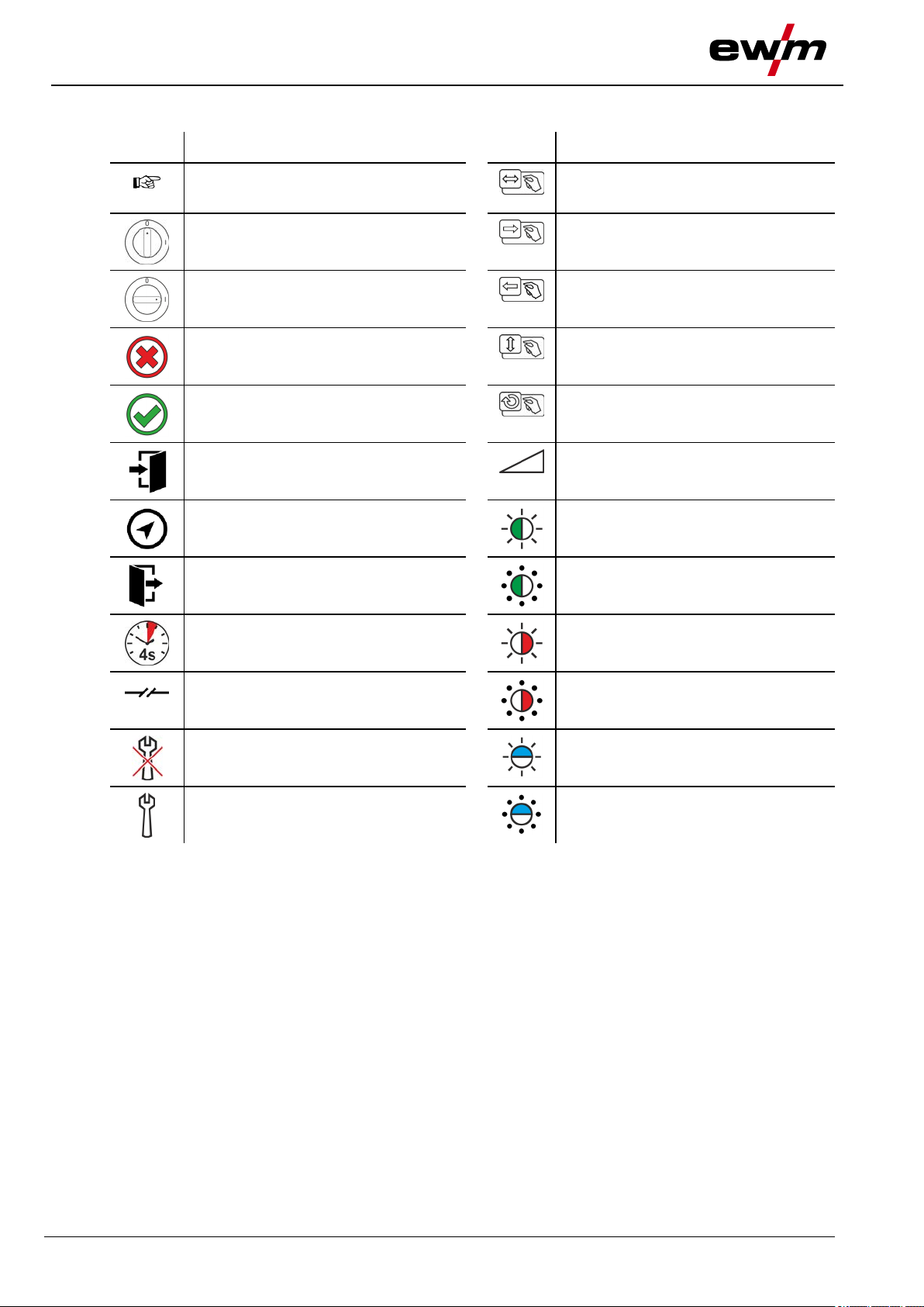
2.2 Explanation of icons ............................................................................................................... 6
2.3 Safety instructions .................................................................................................................. 7
2.4 Transport and installation .................................................................................................... 10
3Intended use ................................................................................................................................. 12
3.1 Applications .......................................................................................................................... 12
3.2 Use and operation solely with the following machines ........................................................ 12
3.3 Documents which also apply ............................................................................................... 12
3.3.1 Warranty ............................................................................................................... 12
3.3.2 Declaration of Conformity ..................................................................................... 12
3.3.3 Service documents (spare parts) ......................................................................... 12
3.3.4 Part of the complete documentation ..................................................................... 13
4Machine description – quick overview ...................................................................................... 14
4.1 Overview of device types ..................................................................................................... 14
4.2 TIG 450 GRIP WD HW ........................................................................................................ 14
4.3 Ways of combination............................................................................................................ 16
5Design and function ..................................................................................................................... 17
5.1 General ................................................................................................................................ 17
5.2 Scope of delivery ................................................................................................................. 17
5.3 Transport and installation .................................................................................................... 18
5.3.1 Ambient conditions ............................................................................................... 18
5.3.2 Welding torch cooling system ............................................................................... 18
5.3.2.1 Permitted torch coolant ......................................................................... 18
5.3.2.2 Maximal hose package length .............................................................. 19
5.3.3 Welding torch connection ..................................................................................... 20
5.3.3.1 Control cable pin configuration ............................................................. 21
5.4 Equipment recommendations .............................................................................................. 22
5.5 Equipping the welding torch ................................................................................................. 24
5.5.1 Convert welding torch ........................................................................................... 25
5.5.1.1 Standard version delivery state ............................................................. 25
5.5.1.2 Converting to jumbo version ................................................................. 27
5.5.1.3 Converting to bottle neck ...................................................................... 29
5.5.2 Assemble the wire guide ...................................................................................... 30
5.5.2.1 Replace steel liner................................................................................. 31
5.5.2.2 Plastic liner ............................................................................................ 35
5.5.3 Configuring the welding machine for mechanical arc fusion welding ................... 40
5.6 Machine control – Operating elements ................................................................................ 40
5.6.1 Operating modes (functional sequences)............................................................. 41
5.6.1.1 Explanation of symbols ......................................................................... 41
5.6.1.2 Non-latched Manual .............................................................................. 42
5.6.1.3 Latched manual ..................................................................................... 43
5.6.1.4 Non-latched automatic .......................................................................... 44
5.6.1.5 Latched automatic ................................................................................. 45
5.6.1.6 Tack welding ......................................................................................... 46
5.6.1.7 superPuls .............................................................................................. 47
6Maintenance, care and disposal ................................................................................................. 48
6.1 General ................................................................................................................................ 48
6.1.1 Identifying damage or worn components ............................................................. 48
6.1.2 Maintenance and care before each use ............................................................... 49
6.1.3 Regular maintenance ........................................................................................... 50
6.2 Disposing of equipment ....................................................................................................... 51
7Rectifying faults ........................................................................................................................... 52
7.1 Checklist for rectifying faults ................................................................................................ 52
7.2 Vent coolant circuit ............................................................................................................... 54

Contents
Notes on using these operating instructions
4
099-500091-EW501
23.02.2023
8Technical data ............................................................................................................................... 55
8.1 TIG 200 GD .......................................................................................................................... 55
8.2 TIG 18, -260, -450, -CW / HW.............................................................................................. 56
9Accessories .................................................................................................................................. 57
9.1 Welding torch cooling system .............................................................................................. 57
9.1.1 Coolant - type blueCool ........................................................................................ 57
9.1.2 Coolant - type KF .................................................................................................. 57
10 Replaceable parts ......................................................................................................................... 58
10.1 TIG 18 .................................................................................................................................. 58
10.2 TIG 260 ................................................................................................................................ 60
10.3 TIG 200 / TIG 450 ................................................................................................................ 61
11 Service documents....................................................................................................................... 63
11.1 Circuit diagram ..................................................................................................................... 63
12 Appendix ....................................................................................................................................... 64
12.1 Searching for a dealer .......................................................................................................... 64

For your safety
Notes on using these operating instructions
099-500091-EW501
23.02.2023
5
2 For your safety
2.1 Notes on using these operating instructions
DANGER
Working or operating procedures which must be closely observed to prevent imminent
serious and even fatal injuries.
• Safety notes include the "DANGER" keyword in the heading with a general warning symbol.
• The hazard is also highlighted using a symbol on the edge of the page.
WARNING
Working or operating procedures which must be closely observed to prevent serious
and even fatal injuries.
• Safety notes include the "WARNING" keyword in the heading with a general warning sym-
bol.
• The hazard is also highlighted using a symbol in the page margin.
CAUTION
Working or operating procedures which must be closely observed to prevent possible
minor personal injury.
• The safety information includes the "CAUTION" keyword in its heading with a general warn-
ing symbol.
• The risk is explained using a symbol on the edge of the page.
Technical aspects which the user must observe to avoid material or equipment damage.
Instructions and lists detailing step-by-step actions for given situations can be recognised via bullet
points, e.g.:
• Insert the welding current lead socket into the relevant socket and lock.

For your safety
Explanation of icons
6
099-500091-EW501
23.02.2023
2.2 Explanation of icons
Symbol
Description
Symbol
Description
Indicates technical aspects which the
user must observe.
Activate and release / Tap / Tip
Switch off machine
Release
Switch on machine
Press and hold
Incorrect / Invalid
Switch
Correct / Valid
Turn
Input
Numerical value – adjustable
Navigation
Signal light lights up in green
Output
Signal light flashes green
Time representation (e.g.: wait 4 s / ac-
tuate)
Signal light lights up in red
Interruption in the menu display (other
setting options possible)
Signal light flashes red
Tool not required/do not use
Signal light lights up in blue
Tool required/use
Signal light flashes blue

For your safety
Safety instructions
099-500091-EW501
23.02.2023
7
2.3 Safety instructions
WARNING
Risk of accidents due to non-compliance with the safety instructions!
Non-compliance with the safety instructions can be fatal!
• Carefully read the safety instructions in this manual!
• Observe the accident prevention regulations and any regional regulations!
• Inform persons in the working area that they must comply with the regulations!
Risk of injury from electrical voltage!
Voltages can cause potentially fatal electric shocks and burns on contact. Even low vol-
tages can cause a shock and lead to accidents.
• Never touch live components such as welding current sockets or stick, tungsten or wire
electrodes!
• Always place torches and electrode holders on an insulated surface!
• Wear the full personal protective equipment (depending on the application)!
• The machine may only be opened by qualified personnel!
• The device must not be used to defrost pipes!
Hazard when interconnecting multiple power sources!
If a number of power sources are to be connected in parallel or in series, only a techni-
cal specialist may interconnect the sources as per standard IEC 60974-9:2010: Installa-
tion and use and German Accident Prevention Regulation BVG D1 (formerly VBG 15) or
country-specific regulations.
Before commencing arc welding, a test must verify that the equipment cannot exceed
the maximum permitted open circuit voltage.
• Only qualified personnel may connect the machine.
• When taking individual power sources out of operation, all mains and welding current leads
must be safely disconnected from the welding system as a whole. (Hazard due to reverse
polarity voltage!)
• Do not interconnect welding machines with pole reversing switch (PWS series) or machines
for AC welding since a minor error in operation can cause the welding voltages to be com-
bined, which is not permitted.
Risk of injury due to radiation or heat!
Arc radiation can lead to skin and eye injuries.
Contact with hot workpieces and sparks can lead to burns.
• Use hand shield or welding helmet with the appropriate safety level (depends on the appli-
cation).
• Wear dry protective clothing (e.g. hand shield, gloves, etc.) in accordance with
the applicable regulations of your country.
• Persons who are not directly involved should be protected with a welding curtain or suitable
safety screen against radiation and the risk of blinding!

For your safety
Safety instructions
8
099-500091-EW501
23.02.2023
WARNING
Risk of injury due to improper clothing!
During arc welding, radiation, heat and voltage are sources of risk that cannot be
avoided. The user has to be equipped with the complete personal protective equipment
at all times. The protective equipment has to include:
• Respiratory protection against hazardous substances and mixtures (fumes and vapours);
otherwise implement suitable measures such as extraction facilities.
• Welding helmet with proper protection against ionizing radiation (IR and UV radiation) and
heat.
• Dry welding clothing (shoes, gloves and body protection) to protect against warm environ-
ments with conditions comparable to ambient temperatures of 100 °C or higher and arcing
and work on live components.
• Hearing protection against harming noise.
Explosion risk!
Apparently harmless substances in closed containers may generate excessive pressure
when heated.
• Move containers with inflammable or explosive liquids away from the working area!
• Never heat explosive liquids, dusts or gases by welding or cutting!
Fire hazard!
Due to the high temperatures, sparks, glowing parts and hot slag that occur during
welding, there is a risk of flames.
• Be watchful of potential sources of fire in the working area!
• Do not carry any easily inflammable objects, e.g. matches or lighters.
• Ensure suitable fire extinguishers are available in the working area!
• Thoroughly remove any residue of flammable materials from the workpiece prior to starting
to weld.
• Only further process workpieces after they have cooled down. Do not allow them to contact
any flammable materials!

For your safety
Safety instructions
099-500091-EW501
23.02.2023
9
CAUTION
Smoke and gases!
Smoke and gases may lead to shortness of breath and poisoning! The ultraviolet radia-
tion of the arc may also convert solvent vapours (chlorinated hydrocarbon) into poiso-
nous phosgene.
• Ensure sufficient fresh air!
• Keep solvent vapours away from the arc beam field!
• Wear suitable respiratory protection if necessary!
• To prevent the formation of phosgene, residues of chlorinated solvents on workpieces must
first be neutralised using appropriate measures.
Noise exposure!
Noise exceeding 70 dBA can cause permanent hearing damage!
• Wear suitable ear protection!
• Persons located within the working area must wear suitable ear protection!
According to IEC 60974-10, welding machines are divided into two classes of
electromagnetic compatibility (the EMC class can be found in the Technical
data) > see 8 chapter:
Class A machines are not intended for use in residential areas where the power supply comes
from the low-voltage public mains network. When ensuring the electromagnetic compatibility of
class A machines, difficulties can arise in these areas due to interference not only in the supply
lines but also in the form of radiated interference.
Class B machines fulfil the EMC requirements in industrial as well as residential areas, inclu-
ding residential areas connected to the low-voltage public mains network.
Setting up and operating
When operating arc welding systems, in some cases, electro-magnetic interference can occur
although all of the welding machines comply with the emission limits specified in the standard.
The user is responsible for any interference caused by welding.
In order to evaluate any possible problems with electromagnetic compatibility in the
surrounding area, the user must consider the following: (see also EN 60974-10 Appendix A)
• Mains, control, signal and telecommunication lines
• Radios and televisions
• Computers and other control systems
• Safety equipment
• The health of neighbouring persons, especially if they have a pacemaker or wear a hearing
aid
• Calibration and measuring equipment
• The immunity to interference of other equipment in the surrounding area
• The time of day at which the welding work must be carried out
Recommendations for reducing interference emission
• Mains connection, e.g. additional mains filter or shielding with a metal tube
• Maintenance of the arc welding system
• Welding leads should be as short as possible and run closely together along the ground
• Potential equalization
• Earthing of the workpiece. In cases where it is not possible to earth the workpiece directly,
it should be connected by means of suitable capacitors.
• Shielding from other equipment in the surrounding area or the entire welding system
Electromagnetic fields!
The power source can create electrical or electromagnetic fields that may impair the
function of electronic systems such as EDP and CNC devices, telecommunication,
power and signal lines as well as pacemakers and defibrillators.
• Follow the maintenance instructions > see 6.1.3 chapter!
• Unwind the welding leads completely!
• Shield radiation-sensitive equipment or facilities appropriately!
• The function of pacemakers may be impaired (seek medical advice if necessary).

For your safety
Transport and installation
10
099-500091-EW501
23.02.2023
CAUTION
Obligations of the operator!
The respective national directives and laws must be complied with when operating the
machine!
• Implementation of national legislation relating to framework directive 89/391/EEC on the int-
roduction of measures to encourage improvements in the safety and health of workers at
work and associated individual guidelines.
• In particular, directive 89/655/EEC concerning the minimum safety and health requirements
for the use of work equipment by workers at work.
• The regulations applicable to occupational safety and accident prevention in the country
concerned.
• Setting up and operating the machine as per IEC 60974.-9.
• Brief the user on safety-conscious work practices on a regular basis.
• Regularly inspect the machine as per IEC 60974.-4.
The manufacturer's warranty becomes void if non-genuine parts are used!
• Only use system components and options (power sources, welding torches, electrode hold-
ers, remote controls, spare parts and replacement parts, etc.) from our range of products!
• Only insert and lock accessory components into the relevant connection socket when the ma-
chine is switched off.
Requirements for connection to the public mains network
High-performance machines can influence the mains quality by taking current from the mains
network. For some types of machines, connection restrictions or requirements relating to the
maximum possible line impedance or the necessary minimum supply capacity at the interface
with the public network (Point of Common Coupling, PCC) can therefore apply. In this respect,
attention is also drawn to the machines' technical data. In this case, it is the responsibility of the
operator, where necessary in consultation with the mains network operator, to ensure that the
machine can be connected.
2.4 Transport and installation
WARNING
Risk of injury due to improper handling of shielding gas cylinders!
Improper handling and insufficient securing of shielding gas cylinders can cause seri-
ous injuries!
• Observe the instructions from the gas manufacturer and any relevant regulations concern-
ing the use of compressed air!
• Do not attach any element to the shielding gas cylinder valve!
• Prevent the shielding gas cylinder from heating up.

For your safety
Transport and installation
099-500091-EW501
23.02.2023
11
CAUTION
Risk of accidents due to supply lines!
During transport, attached supply lines (mains leads, control cables, etc.) can cause
risks, e.g. by causing connected machines to tip over and injure persons!
• Disconnect all supply lines before transport!
Risk of tipping!
There is a risk of the machine tipping over and injuring persons or being damaged itself
during movement and set up. Tilt resistance is guaranteed up to an angle of 10° (ac-
cording to IEC 60974-1).
• Set up and transport the machine on level, solid ground.
• Secure add-on parts using suitable equipment.
Risk of accidents due to incorrectly installed leads!
Incorrectly installed leads (mains, control and welding leads or intermediate hose pack-
ages ) can present a tripping hazard.
• Lay the supply lines flat on the floor (avoid loops).
• Avoid laying the leads on passage ways.
Risk of injury from heated coolant and its connections!
The coolant used and its connection or connection points can heat up significantly
during operation (water-cooled version). When opening the coolant circuit, escaping
coolant may cause scalding.
• Open the coolant circuit only when the power source or cooling unit is switched off!
• Wear proper protective equipment (protective gloves)!
• Seal open connections of the hose leads with suitable plugs.
The units are designed for operation in an upright position!
Operation in non-permissible positions can cause equipment damage.
• Only transport and operate in an upright position!
Accessory components and the power source itself can be damaged by incorrect connection!
• Only insert and lock accessory components into the relevant connection socket when the
machine is switched off.
• Comprehensive descriptions can be found in the operating instructions for the relevant ac-
cessory components.
• Accessory components are detected automatically after the power source is switched on.
Protective dust caps protect the connection sockets and therefore the machine against dirt and
damage.
• The protective dust cap must be fitted if there is no accessory component being operated on
that connection.
• The cap must be replaced if faulty or if lost!

Intended use
Applications
12
099-500091-EW501
23.02.2023
3 Intended use
WARNING
Hazards due to improper usage!
The machine has been constructed to the state of the art and any regulations and stand-
ards applicable for use in industry and trade. It may only be used for the welding proce-
dures indicated at the rating plate. Hazards may arise for persons, animals and material
objects if the equipment is not used correctly. No liability is accepted for any damages
arising from improper usage!
• The equipment must only be used in line with its designated purpose and by trained or
expert personnel!
• Do not improperly modify or convert the equipment!
3.1 Applications
Welding torch for TIG welding with arc welding machines.
3.2 Use and operation solely with the following machines
TIG 200 GRIP
GD CW U/D
HFL
TIG 260 GRIP
WD CW U/D
HFL WO
TIG 260 GRIP
WD HW U/D
HFL WO
TIG 450 GRIP
WD CW U/D
HFL WO
TIG 450 GRIP
WD HW U/D
HFL WO
tigSpeed drive
45 hotwire
tigSpeed drive
45 coldwire
Tetrix drive 4L
Tetrix 270 hot-
wire
3.3 Documents which also apply
3.3.1 Warranty
For more information refer to the "Warranty registration" brochure supplied and our information regarding
warranty, maintenance and testing at www.ewm-group.com!
3.3.2 Declaration of Conformity
This product corresponds in its design and construction to the EU directives listed in the decla-
ration. The product comes with a relevant declaration of conformity in the original.
The manufacturer recommends carrying out the safety inspection according to national and in-
ternational standards and guidelines every 12 months (from commissioning).
3.3.3 Service documents (spare parts)
WARNING
No improper repairs and modifications!
To prevent injuries and damage to the machine, only competent personnel (authorised
service personnel) are allowed to repair or modify the machine.
Unauthorised manipulations will invalidate the warranty!
• Instruct competent personnel (authorised service personnel) to repair the machine.
Spare parts can be obtained from the relevant authorised dealer.

Intended use
Documents which also apply
099-500091-EW501
23.02.2023
13
3.3.4 Part of the complete documentation
This document is part of the complete documentation and valid only in combination with all other
parts of these instructions! Read and observe the operating instructions for all system
components, especially the safety instructions!
The illustration shows a general example of a welding system.
Figure 3-1
Item
Operating instructions
A.1
Wire feeder
A.2
Power source
A.3
Remote control
A.4
Control
A.5
Welding torch
A
Complete documentation

Machine description – quick overview
Overview of device types
14
099-500091-EW501
23.02.2023
4 Machine description – quick overview
4.1 Overview of device types
Version
Functions
Torch type
CW
Cold wire
Cold wire welding.
TIG 200, TIG 260,
TIG 450, TIG-SR 18
GRIP
Grip
Ergonomic grip for secure handling.
TIG 200, TIG 260,
TIG 450, TIG-SR 18
GD
Standard
Gas-cooled with decentral connection.
TIG 200
HFL
Highly flexible hose package
TIG 200, TIG 260,
TIG 450, TIG-SR 18
HW
Hot wire
Hot-wire welding.
TIG 260, TIG 450
TIG-SR 18
WD
Standard
Water-cooled with decentral connection.
TIG 260, TIG 450
TIG-SR 18
U/D
Up/down torch
Setting and display of welding current, programs or JOB.
TIG 200, TIG 260,
TIG 450, TIG-SR 18
WO
Wire outside
External wire feed for particularly soft or hard welding wires
TIG 260, TIG 450
TIG-SR 18
4.2 TIG 450 GRIP WD HW
The illustration serves as an example only.
Figure 4-1
Item
Symbol
Description 0
1
Crown nut
2
Connecting sleeve
3
Contact tip (wire guide)
4
Filler wire guide
5
Tungsten electrode
6
Gas nozzle
7
Torch body
8
Operating elements > see 5.6 chapter
9
Filler wire guide - WO version
10
Back cap

Machine description – quick overview
TIG 450 GRIP WD HW
099-500091-EW501
23.02.2023
15
Item
Symbol
Description 0
11
Support plate
12
Welding current connector plug (hot wire) - HW version
Minus potential
13
Rapid-action closure nipple, red - WD version
Coolant return
14
Rapid-action closure nipple, blue - WD version
Coolant supply
15
Connecting nipple, shielding gas
Rapid-action closure
16
Control lead cable plug
17
Welding current connection (TIG)
decentralised, minus potential
18
Wire guide connector plug

Machine description – quick overview
Ways of combination
16
099-500091-EW501
23.02.2023
4.3 Ways of combination
Figure 4-2
Item
Symbol
Description 0
1
Filler wire guide Fix 30°/39°/42°
2
Flexible filler wire guide (15°–41°)
3
Gas nozzle for jumbo version > see 5.5.1.2 chapter
4
Bottle neck gas nozzle version > see 5.5.1.3 chapter
5
Filler wire guide - WO version

Design and function
General
099-500091-EW501
23.02.2023
17
5 Design and function
5.1 General
WARNING
Risk of injury from electrical voltage!
Contact with live parts, e.g. power connections, can be fatal!
• Observe the safety information on the first pages of the operating instructions!
• Commissioning must be carried out by persons who are specifically trained in handling
power sources!
• Connect connection or power cables while the machine is switched off!
CAUTION
Risk of injury due to moving parts!
The wire feeders are equipped with moving parts, which can trap hands, hair, clothing
or tools and thus injure persons!
• Do not reach into rotating or moving parts or drive components!
• Keep casing covers or protective caps closed during operation!
Risk of injury due to welding wire escaping in an unpredictable manner!
Welding wire can be conveyed at very high speeds and, if conveyed incorrectly, may es-
cape in an uncontrolled manner and injure persons!
• Before mains connection, set up the complete wire guide system from the wire spool to the
welding torch!
• Check wire guide at regular intervals!
• Keep all casing covers or protective caps closed during operation!
Accessory components and the power source itself can be damaged by incorrect connection!
• Only insert and lock accessory components into the relevant connection socket when the
machine is switched off.
• Comprehensive descriptions can be found in the operating instructions for the relevant ac-
cessory components.
• Accessory components are detected automatically after the power source is switched on.
Protective dust caps protect the connection sockets and therefore the machine against dirt and
damage.
• The protective dust cap must be fitted if there is no accessory component being operated on
that connection.
• The cap must be replaced if faulty or if lost!
Read and observe the documentation to all system and accessory components!
5.2 Scope of delivery
The delivery is checked and packaged carefully before dispatch, however it is not possible to exclude the
possibility of damage during transit.
Receiving inspection
• Check that the delivery is complete using the delivery note!
In the event of damage to the packaging
• Check the delivery for damage (visual inspection)!
In the event of complaints
If the delivery has been damaged during transport:
• Please contact the last haulier immediately!
• Keep the packaging (for possible checking by the haulier or for the return shipment).
Packaging for returns
If possible, please use the original packaging and the original packaging material. If you have any queries
on packaging and protection during transport, please contact your supplier.

Design and function
Transport and installation
18
099-500091-EW501
23.02.2023
5.3 Transport and installation
CAUTION
Risk of accidents due to supply lines!
During transport, attached supply lines (mains leads, control cables, etc.) can cause
risks, e.g. by causing connected machines to tip over and injure persons!
• Disconnect all supply lines before transport!
5.3.1 Ambient conditions
Equipment damage due to contamination!
Unusually high amounts of dust, acids, corrosive gases or substances can damage the machine
(observe maintenance intervals > see 6.1.3 chapter).
• Avoid large amounts of smoke, steam, oily fumes, grinding dust and corrosive ambient air!
In operation
Temperature range of the ambient air:
• -10 °C to +40 °C (-13 F to 104 F) [1]
Relative humidity:
• up to 50 % at 40 °C (104 F)
• up to 90 % at 20 °C (68 F)
Transport and storage
Storage in a closed area, temperature range of the ambient air:
• -25 °C to +55 °C (-13 F to 131 F) [1]
Relative humidity
• up to 90 % at 20 °C (68 F)
[1] Ambient temperature dependent on coolant! Observe the coolant temperature range of the torch coo-
ling
5.3.2 Welding torch cooling system
Material damage due to unsuitable coolants!
Unsuitable coolant, coolants mixed with other types / liquids or use in an unsuitable tempera-
ture range will result in material damage and loss of the manufacturer's warranty!
• Operation without coolant is not permitted! Dry running will destroy the cooling components
such as the coolant pump, welding torch and hose packages.
• Only use the coolants described in these instructions for the specified ambient conditions
(temperature range) > see 5.3.2.1 chapter.
• Do not mix coolants of different types (including those described in these instructions).
• When changing the coolant, all liquid must be replaced and the cooling system flushed.
Dispose of the coolant in accordance with local regulations and the material safety data sheets.
5.3.2.1 Permitted torch coolant
Coolant
Temperature range
blueCool -10
-10 °C to +40 °C (14 °F to +104 °F)
KF 23E (Standard)
-10 °C to +40 °C (14 °F to +104 °F)
KF 37E
-20 °C to +30 °C (-4 °F to +86 °F)
blueCool -30
-30 °C to +40 °C (-22 °F to +104 °F)

Design and function
Transport and installation
099-500091-EW501
23.02.2023
19
5.3.2.2 Maximal hose package length
All information relates to the total hose package length of the complete welding system and presents
exemplary configurations (of components of the EWM product portfolio with standard lengths). A straight
kink-free installation is to be ensured, taking into account the max. delivery height.
Pump: Pmax = 3,5 bar (0.35 MPa)
--------------------------------------------------------------------------------------------------------------------- ►
Power source
Hose package
Wire feeder
miniDrive
Welding torch
Max.
Compact
(25 m / 82 ft.)
(5 m / 16 ft.)
30 m
98 ft.
(20 m / 65 ft.)
(5 m / 16 ft.)
Decompact
(25 m / 82 ft.)
(5 m / 16 ft.)
(15 m / 49 ft.)
(10 m / 32 ft.)
(5 m / 16 ft.)
Pump: Pmax = 4.5 bar (0.45 MPa)
--------------------------------------------------------------------------------------------------------------------- ►
Power source
Hose package
Wire feeder
miniDrive
Welding torch
Max.
Compact
(25 m / 82 ft.)
(5 m / 16 ft.)
30 m
98 ft.
(30 m / 98 ft.)
(5 m / 16 ft.)
40 m
131 ft.
Decompact
(40 m / 131 ft.)
(5 m / 16 ft.)
45 m
147 ft.
(40 m / 131 ft.)
(25 m / 82 ft.)
(5 m / 16 ft.)
70 m
229 ft.

Design and function
Transport and installation
20
099-500091-EW501
23.02.2023
5.3.3 Welding torch connection
Equipment damage due to improperly connected coolant pipes!
If the coolant pipes are not properly connected or a gas-cooled welding torch is used, the coo-
lant circuit is interrupted and equipment damage can occur.
• Connect all coolant pipes correctly!
• Completely unroll the hose package and the torch hose package!
• Observe maximal hose package length > see 5.3.2.2 chapter.
• When using a gas-cooled welding torch, use a hose bridge to establish the coolant cir-
cuit > see 9 chapter.
Prepare welding torch according to the welding task in hand (see operating instructions for the torch).
Figure 5-1
Item
Symbol
Description 0
1
Welding torch
Observe additional system documents!
2
Welding torch hose package
3
Wire electrode connection
Welding torch wire feed
4
Quick connect coupling (red)
coolant return
5
Quick connect coupling (blue)
coolant supply
6
Connection socket (12-pole)
Welding torch control lead
7
Connection socket (TIG hot wire)
Hot wire power, minus potential
8
Quick connect coupling
Shielding gas
9
Connection socket (TIG)
Welding current, minus potential
This manual suits for next models
6
Table of contents
Other EWM Flashlight manuals