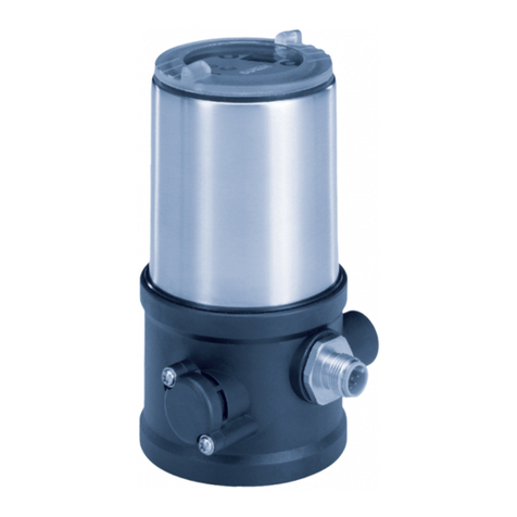
EWS UF3020 User manual

Instruction manual for ultra filtration plants
UF3020
Instruction manual
Software version 2.00

Contents
General description……………....…....………................................................… 1
“Standby” step
“Filtration” step
“Pre flush” step
“Flush1” step
“Backwash” step
“Flush2” step
“Alarm” step
Function display…...….........................................................................………..… 6
Info display…………………..................................................………….………….. 9
Input functions……………………….…......................................................……… 11
Over pressure
Low level raw water tank
High level clean water tank
Output functions…………...........................................................…….…………… 13
Display and modifications of set points..................................................….… 14
1. Language
2. Process
3. Input functions
4. Power up mode
Wiring diagram…………..…………...................................................….………… 20
Technical data…….............…..……….……...........................................…....…… 21
Declaration of conformity……..…….……............................................…........… 22

UF3020 General description 1
General description
The UF3020 operating control is used to fully automatically monitor and control very
simple ultra filtration water treatment systems.
The basic values that have been programmed into the operating control can be
changed at any moment and are not erased in case of a power failure.
The control has seven switching steps, namely "Standby", "Filtration", “Pre flush”,
“Flush1”, “Backwash”, “Flush2” and “Alarm”.
The steps “Pre flush”, “Flush1” and “Flush2” are programmable to be switched off
and on.
The state of the outputs during a step is programmable for each step.

UF3020 General description 2
"Standby” step
During standby the low level (RW tank) and high level (CW tank) will be checked.
When both are not activated the installation will switch to “Pre flush“ (if activated
in step 2.1) and then to “Filtration“.
When the push button will be pressed the controller will start a flush.
All outputs free programmable.
The following values are monitored:
-Low level, raw water tank
-High level, clean water tank
"Filtration" step
During filtration the low level (RW tank) and high level (CW tank) will be checked.
When one or both are activated the installation will switch to standby.
When the push button will be pressed the controller will start a flush.
After a programmed interval time the installation will switch to “Flush1” (if activated
In step 2.1).
All outputs free programmable.
The following values are monitored:
-Overpressure
-Low level, raw water tank
-High level, clean water tank
-Push button

UF3020 General description 3
"Pre flush” step
This step has to be activated in step 2.1 (PFL).
The step “Pre flush” will be activated after switching power on (when program step
4.1 is programmed for ‘PFL)’ or when the installation will go to the “Filtration” step
after “Standby”.
After a programmed time the installation will go into “Filtration”.
All outputs free programmable.
The following values are monitored:
-Overpressure
"Flush 1” step
This step has to be activated in step 2.1 (FL1).
The installation will switch to “Flush 1” after the “Filtration” time has passed.
You can also start “Flush 1” manually by pressing the push button during “Standby”
or “Filtration”.
After a programmed time the installation will switch to “Backwash”.
All outputs free programmable.
The following values are monitored:
-Overpressure

UF3020 General description 4
"Backwash” step
The installation will switch to “Backwash” after the “Flush 1” time has passed.
After a programmed time the installation will switch to “Flush 2”,
All outputs free programmable.
The following values are monitored:
-Overpressure
"Flush 2” step
This step has to be activated in step 2.1 (FL2).
The installation will switch to “Flush 2” after the “Back wash” time has passed.
After a programmed time the installation will switch to “Filtration” or “Standby”
(depending on the state of the level switches).
All outputs free programmable.
The following values are monitored:
-Overpressure

UF3020 General description 5
"Alarm” step
The installation will switch to “Alarm” when there is a overpressure situation or when
program step 4.1 is programmed “AL”.
During alarm the over pressure switch and the button will be checked.
When pressing the button and the pressure is ok the installation will proceed the
process step that was interrupted. The interval time for the flush and back wash
steps will also proceed and not be reset.
All outputs will be deactivated.
The following values are monitored:
-Overpressure
-Push button

UF3020 Function display 6
Function display
First LCD line
The first line of the LCD display shows the actual phase of the system: "Standby",
"Filtration", “Pre flush”, “Flush1”, “Backwash”, “Flush2”, “Alarm”.
Second LCD line
Depending on the current phase of the system, the second line of the LCD display
shows operating values.
Second LCD line for the "Standby" step
Raw water tank empty and clean
water tank not full.
Raw water tank not empty and
clean water tank full.
Raw water tank empty and clean
water tank full.
Standby
RW empty/CW low
Standby
RW high /CW full
Standby
RW empty/CW full

UF3020 Function display 7
Second LCD line for the "Filtration" step
The second line indicates the remaining time until “Flush 1” will start.
When the start is within 60 seconds the remaining time will be displayed in seconds.
Second LCD line for the "Pre flush" step
The second line indicates the remaining time of “Flush 1”.
Second LCD line for the "Flush 1" step
The second line indicates the remaining time of “Flush 1”.
Filtration
Time 10m
Filtr
ation
Time 59s
Pre flush
Time 10s
Flush 1
Time 10s

UF3020 Function display 8
Second LCD line for the "Backwash" step
The second line indicates the remaining time of “Backwash”.
Second LCD line for the "Flush 2" step
The second line indicates the remaining time of “Flush 2”.
Second LCD line for the "Alarm" step
The second line indicates the cause of the alarm situation.
“Overpressure” : Overpressure situation during flushing or backwash.
“Supply failure” : Controller switched on and step 4.1 programmed at “AL”.
Flush 2
Time 10s
Back wash
Time 10s
Alarm
Overpressure
Alarm
Supply failure

UF3020 Info display 9
Info display
The information key can be used to retrieve various information. When
you press the information key, the first information is displayed.
You can obtain further information by pressing the key again.
Input switch positions
Here the current switch positions of the input functions are displayed
(“-“ input not activated, “|” input activated) :
OP = over pressure switch
LL = low level raw water tank
HL = high level clean water tank
Output switch positions
Here the current switch positions for the IV, PU and AL outputs are displayed.
A = IV
B = PU
C = AL
Input
OP- LL- HL-
Output
ABC
||-

UF3020 Info display 10
Software version
The factory regularly updates the software. Changes are made as necessary to
adapt the product to the latest insights and requirements. Displayed is the number
of the built-in version.
Software version
UF3020 1.01.00

UF3020 Input functions 11
Input functions
The ‘Over pressure’ (CC), ‘Low level raw water tank’ (LP) and ‘High level clean
water tank’ (FU) inputs are standard available.
Overpressure
The ‘Over pressure’ (CC) input is used to prevent the installation from to high
pressures.
In step 3.3 you can program the delay before the system is switched to “Alarm”.
You can leave the “Alarm” step by pressing the button when the when over pressure
situation is solved.
The input function is active when the contact is open.
Low level raw water tank
The input function ‘Low level raw water tank’ (LP) is used for checking the level of
water in the raw water tank.
The controller will respond immediately when the contact is opened and will switch
into the step “Standby”.
In step 3.1 you can program the delay for the installation to switch back the step
“Filtration” (through the step “Pre flush”, if programmed in step 2.1).
The controller is detecting low level when the contact is open.

UF3020 Input functions 12
High level clean water tank
The input function ‘High level clean water tank’ (FU) is used for checking the level of
water in the clean water tank.
The controller will respond immediately when the contact is opened and will switch
into the step “Standby”.
In step 3.2 you can program the delay for the installation to switch back the step
“Filtration” (through the step “Pre flush”, if programmed in step 2.1).
The controller is detecting high level when the contact is open.

UF3020 Output functions 13
Output functions
The outputs are free programmable for each process step.
There are no special output functions available.

UF3020 Display and modification of set points 14
Display and modification of set points
Attention
Changing settings may only be done by qualified electrical engineers.
When the system is put into operation, the operational data of the reverse osmosis
system can be controlled by entering basic values.
You can change these values at any time and they are not erased in case of a
power failure.
To prevent unwanted changes in the programme, you must keep the
key depressed for four seconds before the system allows you to make
changes
With the same key you can then browse through the programming.
You leave the programming mode automatically about two minutes after
the last keystroke or by pressing the key combination as shown.
With the upper key you can move the cursor.
By pressing the lower key you can change numeric values within the
given range that you have first marked with the cursor.
For questions with a choice, you can also use this key to switch
between ‘-‘ en ‘|’.

UF3020 Display and modification of set points 15
1. Language
In this step you can set the language.
2. Process step times
In this program step you can activate or deactivate the steps “Pre flush”, “Flush 1”
and “Flush “.
PFL = “Pre flush”
FL1 = “Flush 1”
FL2 = “Flush 2”
If a step is not activated the corresponding steps will be skipped.
In this program step you can program which outputs are activated during the step
“Standby”.
Step no.: 1
.1
D Nl E F
Step no.:
2
.1
PFL-FL1-FL2-
Step no.:
2.2
Standby ---

UF3020 Display and modification of set points 16
In this program step you can program the “pre flush” time between 1 and 999
seconds.
In this program step you can program which outputs are activated during the step
“Pre flush”.
In this program step you can program the filtration time between 1 and 999 minutes.
In this program step you can program which outputs are activated during the step
“Filtration”.
In this program step you can program
“flush 1” time between 1 and 999
seconds.
Step no.: 2.3
Pre flush 30s
Step no.:
2.4
Pre flush ---
Step no.: 2.
5
Filtration 10m
Step no.:
2.
6
Filtration ---
Step n
o.: 2.
7
Flush 1 30s

UF3020 Display and modification of set points 17
In this program step you can program which outputs are activated during the step
“Flush 1”.
In this program step you can program the time for step “Back wash” between 1 and
999 seconds.
In this program step you can program which outputs are activated during the step
“Back wash”.
In this program step you can program the “flush 2” time between 1 and 999
seconds.
In this program step you can program
which outputs are activated during the
step “Flush 2”.
Step no.: 2.
9
Back wash 15s
Step no
.:
2.
8
Flush 1 ---
Step no.:
2.
10
Back wash ---
Step no.: 2.
11
Flush 2 30s
Step no.:
2.
12
Flush 2 ---

UF3020 Display and modification of set points 18
3. Input functions
In this program step you can program the delay for the low level switch of the raw
water tank, between 1 and 999 seconds.
In this program step you can program the delay for the high level switch of the clean
water tank, between 1 and 999 seconds.
In this program step you can program the delay for the overpressure switch between
1 and 999 seconds.
Step no.:
3
.1
Delay LL 1s
Step no.: 3.
2
Delay HL 1s
Step no.: 3.
3
Delay OP 1s
Other manuals for UF3020
1
Table of contents
Other EWS Controllers manuals
Popular Controllers manuals by other brands
Allen-Bradley
Allen-Bradley SMC-50 user manual

CASTLE
CASTLE WFS-25-S operating instructions

THOMSON
THOMSON EAP 110 Installation & operating instructions
Elko
Elko iNELS SA2-02M Manual instructions
Renkus-Heinz
Renkus-Heinz X24 owner's manual
Extreme Networks
Extreme Networks Campus Controller E2122 installation guide
