EWS ES2030 SV User manual
Control for ion exchangers and filter systems
Instruction manual
Software version 3.00
ES2030 SV

Contents
Functional description..................................................................................................................…. 1
Illustration .....................................................................................................................................…. 2
Service and regeneration displays …………...............................................................................…. 3
LED indicator lights…...………………………………………………………………....……………. 3
LCD display………....….....………………………………………………………………....………… 3
First line…….…...……………………………………………………………………...………. 3
Second line during service…….………………………………………………………...……. 3
Second line during regeneration………………………………………………………...……. 3
Displaying and altering program values.......................................................……………………..…. 4
Hardness of supply water / filter capacity..………………………………………………………..... 4
Current time………………………………...………………………………………………………..... 4
Info key ....................................…...........................................................……………………….………. 5
Flush……….……………….………………………………………………………………........…….. 5
Regeneration time..……….………………………………………………………………........…….. 5
Regeneration restrictions…………………………………………………………………........…….. 5
Additional program run……………………………………………………………………........…….. 5
Filter capacity….………………………………………………………………………………………. 5
Water delivery…….………….………………………………………………………………………... 6
Input states……………..………………………………………………………………………..…..... 6
Output states……………..………………………………………………………………………........ 6
Service number….……….……………………………………………………………………………. 6
Software version….…………………………………………………………………………………... 6
Programmed inputs………………………………………………………………………........…….. 6
Programmed outputs……………………………………………………………………………........ 6
Last regeneration.……………………….……………………………………………………………. 6
Regeneration ratio……………………….……………………………………………………………. 6
Messages……………………......................................................................……………………………. 7
Capacity exceeded…. .……………...……………………………………………………………….. 7
Power failure…………..……………...……………………………………………………………….. 7
Refill regeneration medium.…………..……………………………………………………………... 7
Delayed regeneration…..….…......…………………………………………………………………... 7
Stop regeneration……..…....……….………………………………………………………………... 8
Stop service…….…………..……………………………....……………………………………….…. 8
Minimum regeneration interval.…………………………………………………………………….… 8
Cancel buzzer………………......................................................................……………………………. 8
Switching the OUT1 and OUT2 relays on and off .........................…..........................................… 8
Additional output function.....….……………………………………………………………………... 8
Regeneration cycle function….….…..…………………………………………………………….…. 8
Supply pulse function…………………..……………………………………………………………... 8
Warning function..………..……………….…………………………..…………………………….… 8
Desalinate function….……………………...........…………………………………………………... 8
Initiating regeneration manually...............................................................……………………………. 9

Special functions.....................................................................…...............…………………………….. 9
Filter change over without program initiation.……………..………………………………………… 9
Immediate stop…………………...…………………………..………………………………………... 9
Regeneration of standby filter……………………………..…………………………………..……… 9
Switching from parallel to alternate.……………………..…………………………………………... 10
Fast cycle..………...........……….……..………………....…………………………………………... 10
Regeneration without initialisation..…..……………..…..…………………………………………... 10
Regeneration of Filter 1 ONLY…....…..…………..……..…………………………………………... 10
Regeneration of Filter 2 ONLY…....…..………..………..…………………………………………... 10
Displaying and modification of the basic settings...............................……………………………… 11
General information on programming and language settings…….……………………………….. 11
1 Filter switching……..………………………......………………………………………………….. 12
2 Electrical control…..………………………......…………………………………………………... 14
3 Number of regeneration switch phases.…………..……………………………………..……… 15
4 Single valve control….…………………..…………..………………………………………..…... 15
5 Regeneration times……..…………………………………………………………………………. 16
6 Delayed regeneration.……………….……………………………………………………………. 17
Starting on real time clock…………….…………………………………………………………….18
7 Interval start of regeneration…………...…………....................…..…………………………… 18
8 Minimum regeneration distance….....................………………………………………….……. 19
9 Definition of input functions…………………….…….…………..………………………….…… 20
10 “Water meter” input…..……...……………………..…………………..…………………….…… 21
Filter capacity…..…..……...……………………..…………………..…………………..……..… 22
11 “Stop service” input…….…...……………………..…………………..…………………..…...… 22
12 “Start regeneration” input…….…………………..…………………..…………………..…....… 23
13 “Chemical shortage” input…….…………………..…………………..…………………..…....… 23
14 “Stop regeneration” input…….…………………..…………………..…………………..…....… 23
15 Definition of output functions…………………….…….…………..…………………………..… 24
16 “Additional program” output...…………………..……………………..………………………… 25
17 “Regeneration” output.……...…………………..……………………..……………………….… 25
18 “Flow pulse” output..…………………….…………..…………………………..……………...… 26
19 “Warning” output..…………………….…………..…………………………..………………...… 26
20 “Desalinate” output………………….…………..…………………………..…………………..… 27
21 Buzzer…….…………………………………………..…………………..………………………… 27
22 Programming mode.……...…………...…..……………………………..……………………….. 27
Examples of systems……........................................................................……………….…………… 28
Typical electrical wiring diagrams............................................................……………….…………… 29
Wiring diagram ES2030 SV.......................................................................……………….…………… 31
Notes on installation and initial use........................................................……………….…………… 32
Technical data….........................................................................……………………………............… 33
Declaration of conformity...................................................…………….………………….……...…… 34
ES2030 SV Functional description 1
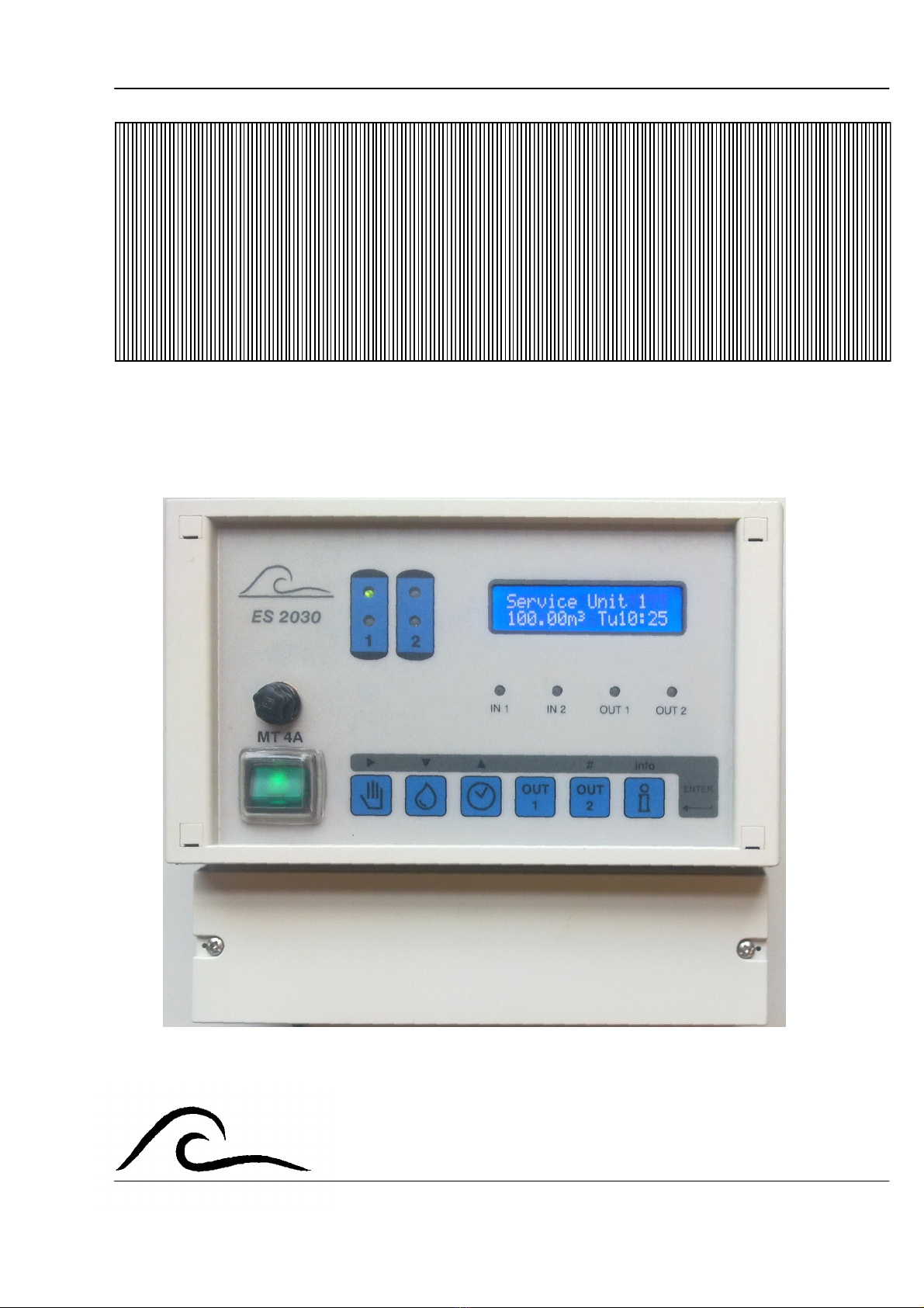
Functional description
The controller ES2030 SV (wall mounted) is
used for the automatic control and monitoring
of single and double filter systems.
If additional control functions are required, they
can be obtained with the IF2030 card, which
can also be installed subsequently.
The software’s flexible programming capacity
and the individually adaptable hardware make
a wide range of uses in water treatment
systems possible. In combination with
individual valves, these control units can
operate ion exchanger systems and filter
systems.
For single filter systems, 6 (or 8, if the IF2030
card is fitted) in relays are available for
controlling individual valves or for controlling
pilot valves or control motors of a multifunction
valve.
Since only 6 (or 8) relays in total are available
for dual filter systems too, individual valve
systems can only be operated as simple
backwashing filters.
NOTE: For the sake of simplicity, in these
instructions the treatment process carried out
by a filter system (e.g. deferrization) is also
referred to as “REGENERATION”, as is usual
in the case of ion exchangers.
A regeneration can be initiated :
1. by manual switch
2. by remote switch (water hardness monitor,
conductivity meter, manual switch, etc..)
3. by pre selected amount (pulse water meter
required)
4. after set time intervals (e.g. every 72 hours)
5. starting on real time clock
A time window can be set to determine times
when regeneration must not take place
(delayed regeneration).
A minimum regeneration distance between
regenerations prevents regenerations being
initiated constantly if the water meter or the
remote switch is faulty.
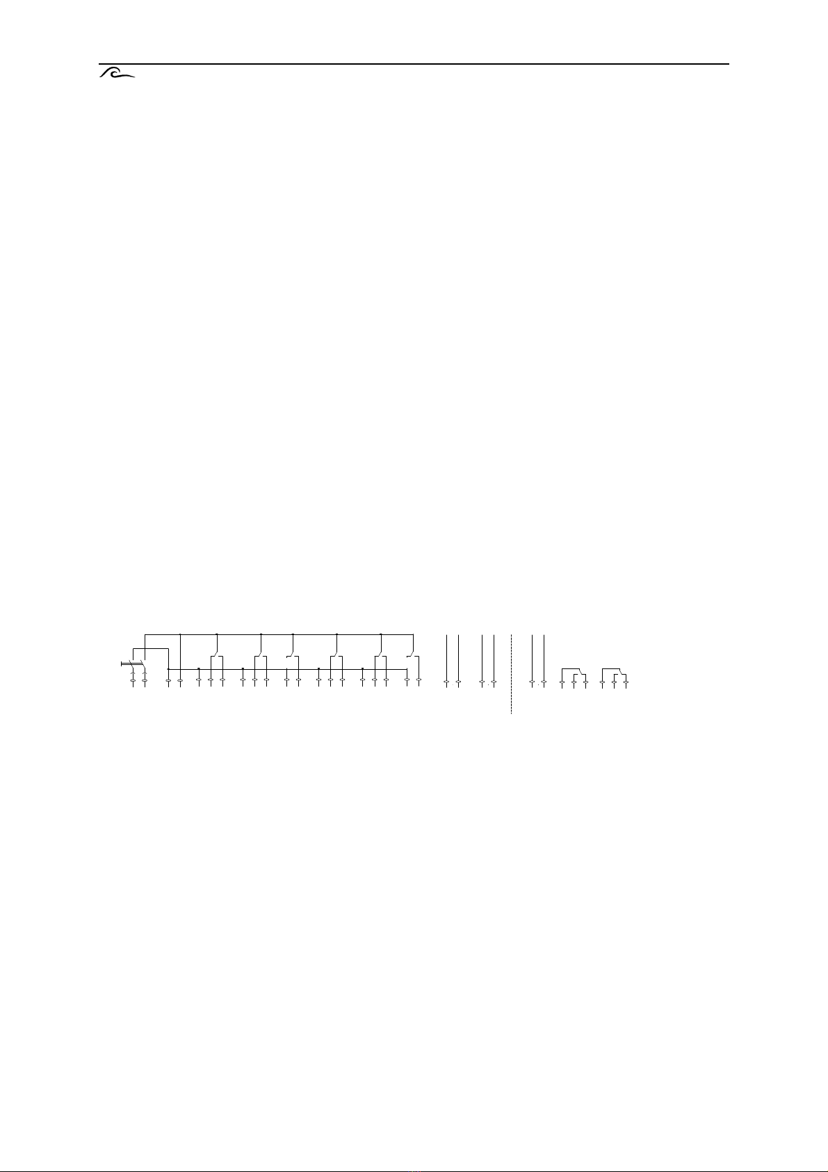
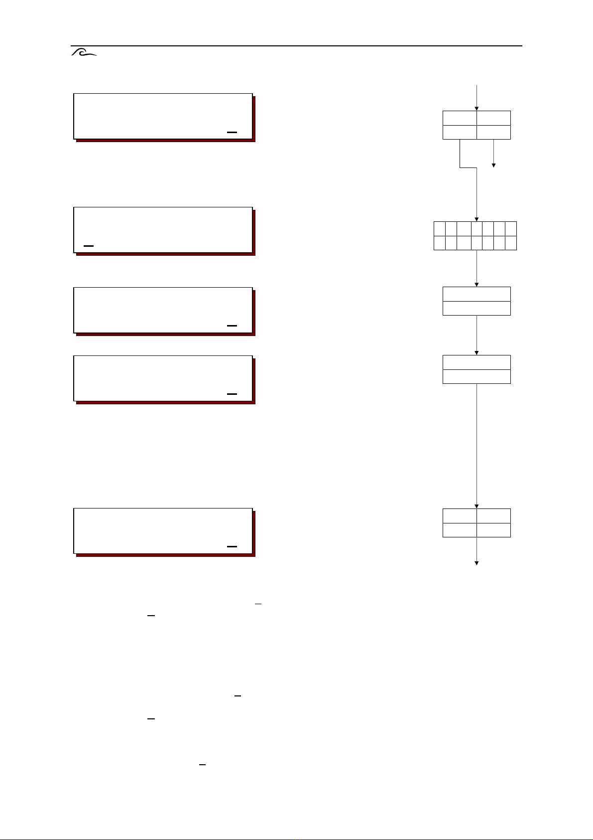
Terminal diagram of ES2030 SV
6 relays for magnetic valves or servo-motors (valve 1 – valve 6)
1 signal input, programmable for the following functions : water meter, stop, start or chemical
shortage
1 12V= output for an external electronic application, e.g. turbines with Hall effect switch (auxiliary
power)
1 power output for “control on” message and power supply to the potential free contacts “OUT1” and
“OUT2” (power out)
Separately available card IF2030 :
1 signal input, programmable for the following functions : water meter, stop, start or chemical
shortage
2 output relays programmable for the following functions : magnetic valves, additional program,
regeneration, flow pulse, warning or desalination. (OUT1 and OUT2).
valve1 valve2 valve3 valve4 valve5 valve6 IN1
auxiliary
power
IN2
power
out
power
in
OUT1
OUT2

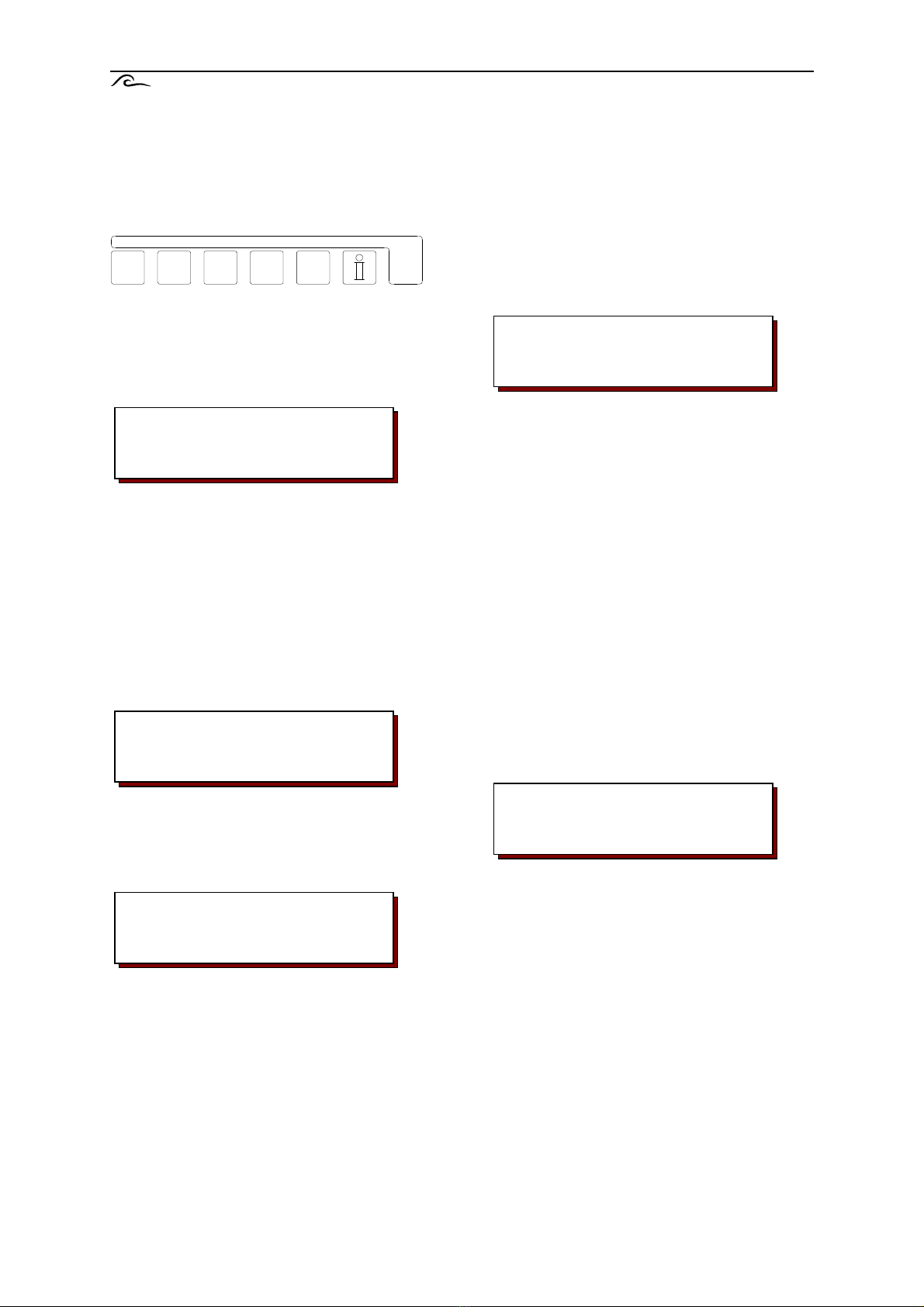
ES2030 SV Illustration 2
Illustration
Wall-mounted
1 Service filter 2 6 Main switch 11 Output 2 16 Input 2 LED
2 Service filter 1 7 Start regeneration 12 Information 17 Output 2 LED
3 Regeneration filter 1 8 Supply water 13 Programming 18 Output 1 LED
4 Regeneration filter 2 9 Time 14 LCD display
5 Main fuse 10 Output 1 15 Input 1 LED
Service unit 1
100.00m3 Mo17:10
MT 4A
1
2
3
4
5
6
8
9
10
11
12
13
14
1 2
IN1
IN2
OUT1
OUT2
#
Enter
info
OUT
1
OUT
2
7
15
16
17
18
ES2030 SV Service and regeneration display 3
Service and regeneration display
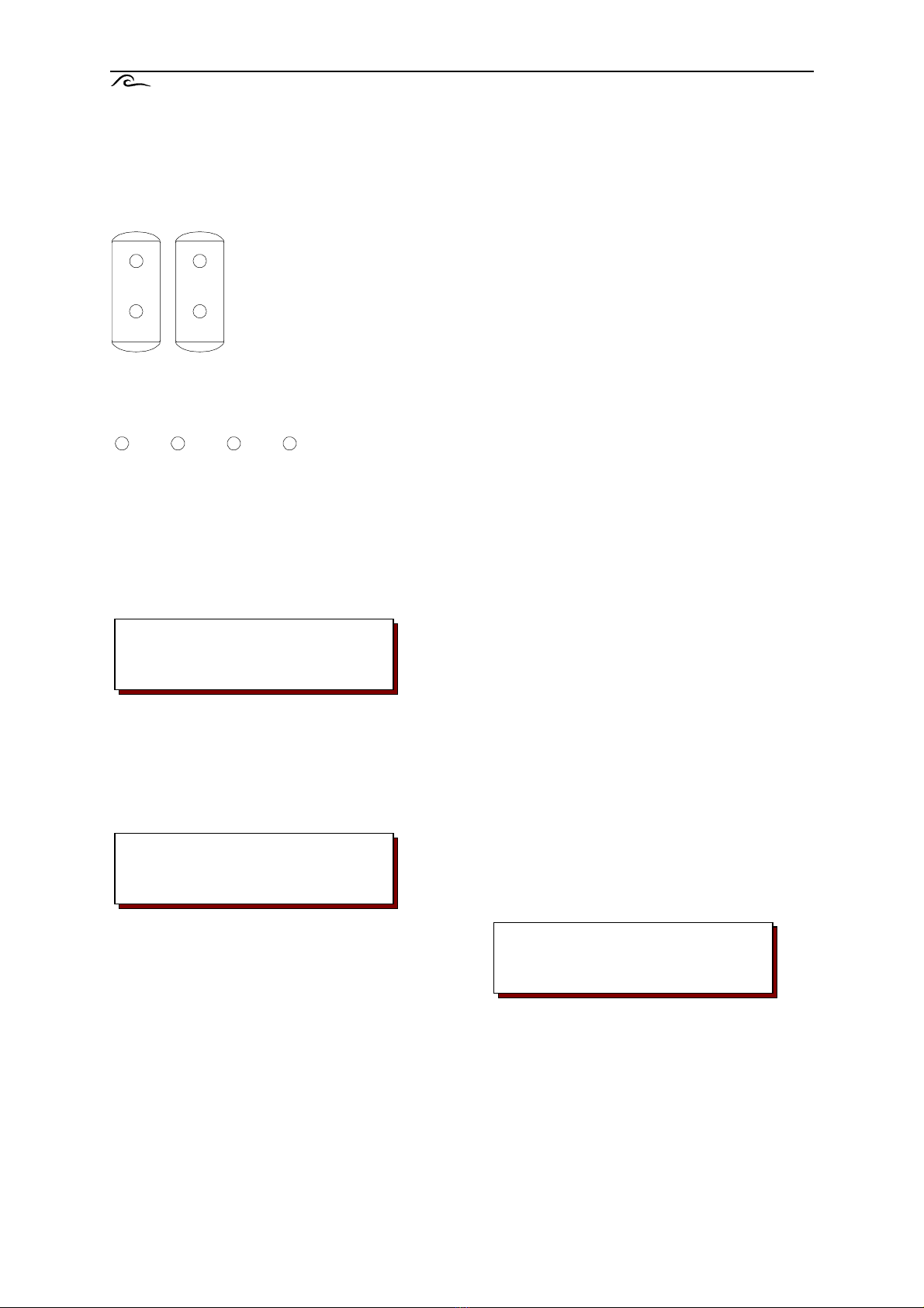
LED control lamps
Coloured control lamps show the unit’s major states :
Filter 1 service (green)
Filter 2 service (green)
Filter 1 regeneration (orange)
Filter 2 regeneration (orange)
IN1 = Input 1 active (orange)
IN2 = Input 2 active (orange)
OUT1 = Output 1 active (orange)
OUT2 = Output 2 active (orange)
LCD display
First LCD line
The first line of the LCD display shows the
present state of the system, e.g. “Filter1 in
service”, “Filter 2 in regeneration” or “not in
service”.
Second LCD line during service
The second line of the LCD display shows the
following information during service:
1. The amount of water remaining until the next
regeneration
or:
The time of the next regeneration if a
‘delayed regeneration’ has been initiated
(see program step 6).
or:
The number of hours until the next
regeneration (see program step 7).
or:
Alternating with the ‘amount of water
remaining’ of the current through flow (see
program step 10.1 : pulse count)
or:
The flushing time remaining (see program
step 19)
or:
“No Autom. Reg” if no automatic initiation of
regeneration was selected (water meter,
time interval).
2. The current time
Second LCD line during regeneration
During regeneration, the second line of the
LCD display shows the remaining time for the
current phase and after the oblique the
remaining time for the whole regeneration.
Or:
Alternating with the regeneration times, the
remaining time for the additional program (see
program step 15).
Service unit 1
100.00m3 Mo12:00
Regener.unit 1
Phase:2 80/100m
1
2
IN1
IN2
OUT1
OUT2
Service unit 1
100.00m3 Mo12:00
ES2030 SV Displaying and altering program values 4
Displaying and altering program values
The main program values can be displayed
and altered if required by pressing a key.
Hardness of supply water /
filter capacity
Press the key with the symbol . In the case
of an ion exchanger the bottom line will show
the present supply water hardness, for a filter
system it will show the capacity entered. (see
program step 10.3).
If you wish to change the value shown, use the
‘ ‘ key to move the cursor under the figure to
be changed, and change the value with the
number key ( ‘#’).
The following values may be entered,
according to the units entered at phase 10.3 of
the basic programming:
Unit of the supply
water hardness : entry value :
°D 2 - 99
°F 4 - 199
°E 2 - 99
mg/l CaCO3 40 -1999
gpg 2 - 99
no unit 0,01 - 9999,99 m3
(0,02 mmol/l = 0,10°D = 0,13 °E =0,18 °F
= 1,79ppm = 0,11gpg(USA) = 0,13gpg(UK))
The calculation of the soft water quantity with
altered values is carried out at the start of each
regeneration using the formula:
NOTE: In the case of remote control valves
with water supply by-pass ports, the water
meter records the dilution amount. The
hardness of the diluted water must therefore
be subtracted from the value to be entered.
Example :
Supply water hardness = 15 °D
Diluted water = 6 °D
This gives an input value of :
15 °D – 6 °D = 9 °D
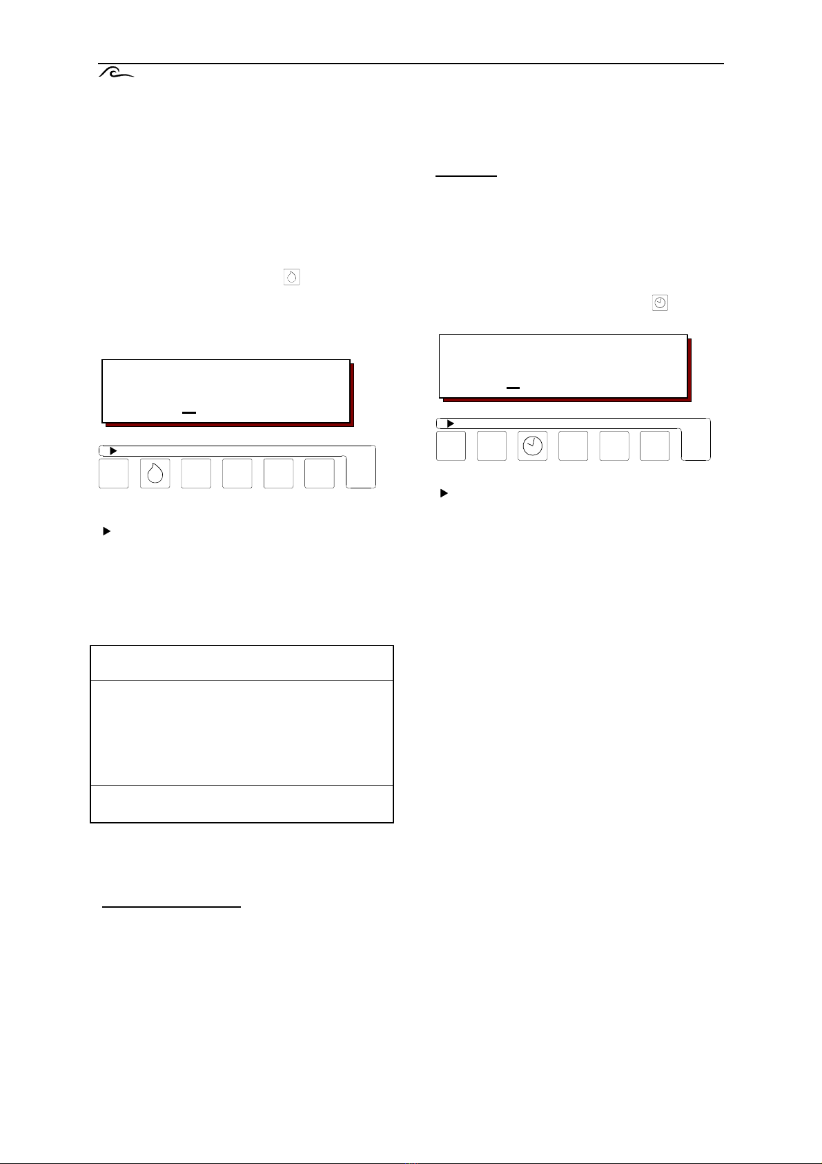
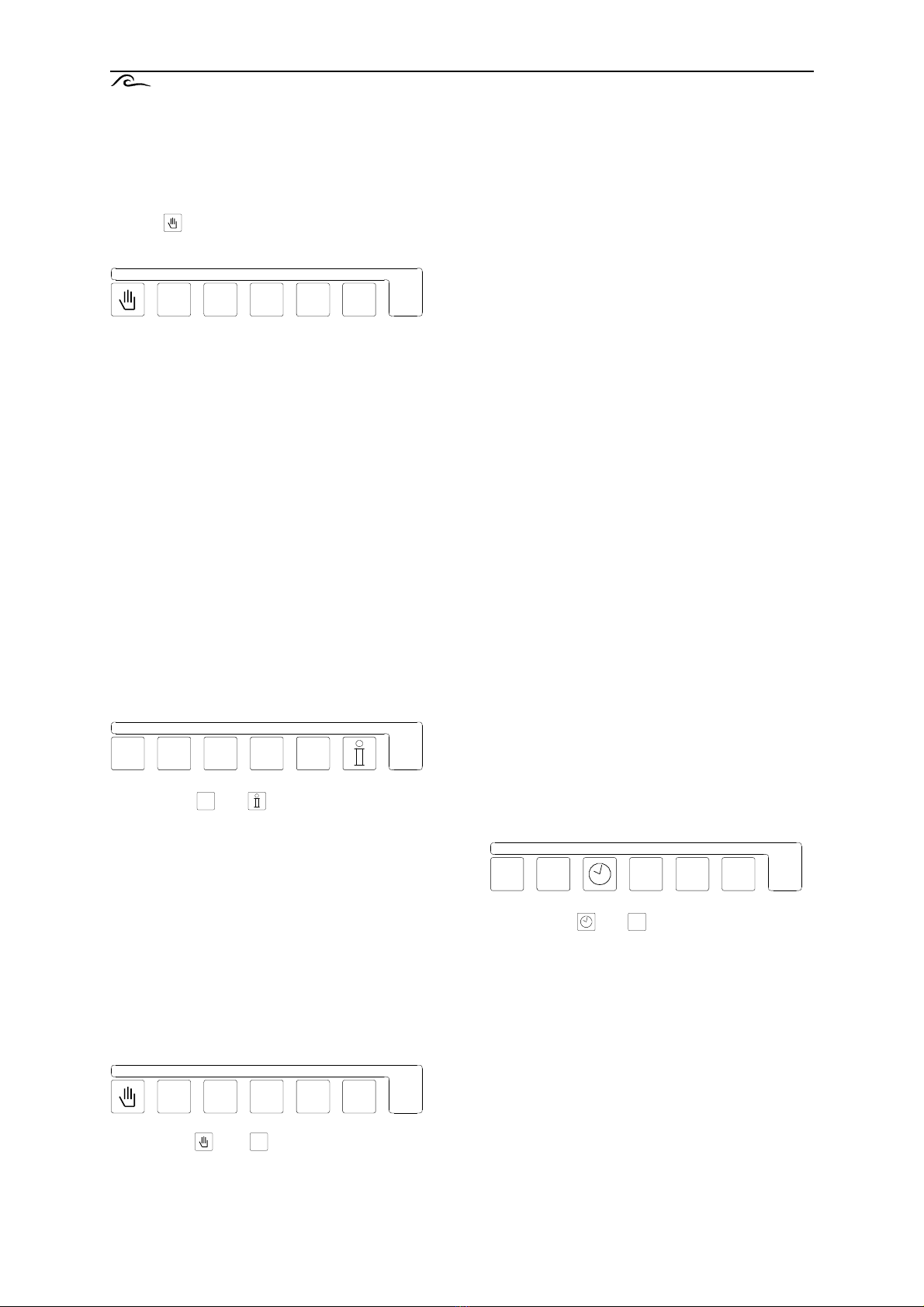
Current time
Press the time key with the symbol . The
current time appears in the lower line.
If you wish to change the value shown, use the
‘ ‘ key to move the cursor under the digit to be
changed, and change the value with the
number key ( ‘#’).
Water hardness:
18°D
Current time
Mo 15:50
#
Exhanger capacity (°D m
3
) .
Supply water hardness (°D)
= soft water quanitity (m
3
)
#
ES2030 SV Info 5
Info key
The information key is used to display various
information and values. Only the service
telephone number can be changed using the
info key.
If the info key is pressed during programming,
the full texts of some abbreviated texts are
shown in the LCD display.
Flushing
The following values are shown :
Top right : Flush time in seconds
Bottom left : quantity of water remaining
before flushing
Bottom right : quantity of water between two
flushes.
NOTE: This display shown only if the flushing
function is selected (see program step 15).
Regeneration time
The total time for a regeneration cycle is
shown.
Regeneration restrictions
NoReg 16:00 – 18:00
If “delayed regeneration” was selected during
programming at step 6, the period in which no
regeneration is to occur is shown.
Otherwise “NoReg ----“ is displayed.
IntRg 72
If “interval start” was selected during
programming at step 7, the time interval in
hours is shown.
Otherwise “IntRg --“ is displayed.
MinRg 4
If a “minimum regeneration distance” was
selected during programming at step 8, the
time interval in hours is shown.
Otherwise “MinRg --“ is displayed.
Additional program
Bottom left : the starting point of the additional
program is shown.
Bottom right : the start time entered is shown
or the time remaining if the additional
program is currently running.
If phase ‘0’ is displayed, the additional program
will first run for its full time, followed by the
regeneration program.
If phase ‘E’ is displayed the regeneration
program will first run completely, then the
additional program.
NOTE: If the additional program function was
not selected during programming at step 14,
“no additional program” will be displayed. If the
IF card is not fitted this display will be omitted.
Filter capacity
The water quantity delivered by a filter
between two regenerations is shown. In the
case of ion exchangers, the calculation is
always carried out using the currently entered
values for filter capacity and the supply water
hardness.
NoReg16:00-18:00
IntRg72 MinRg4
Additional prog.
Phase: 2 20
Unit capacity
100m3
Flushing
500l 500l 20s
info
Regen.time
Σ95m rest.0m

ES2030 SV Info 6
Water delivery
The total quantity of water delivered by the
system is shown.
Input states
Indicates the current state of each input.
(- = Input not activated, | = Input activated)
WM = Water meter SP = Stop service
ST = Start regeneration CH= Chemicals shortage
HO = Stop regeneration
Output states
The current switch states of the output relays
are shown. Each figure has a relay allocated to
it (see switching diagram on p.31).
A horizontal stroke ‘-‘ under a figure means
‘relay switched off’.
A vertical stroke ‘ | ‘ under a figure means
‘relay switched on’.
NOTE: Relays 7 and 8 are only shown if an IF
card is fitted.
Service number
A service phone number is displayed. You can
also change the number here.
Change the phone number :
Select number :
Lower number :
Higher number :
Software version
The software is continuously updated by the
factory. Where necessary changes are made
to reflect new technology and customer
requirements.
The number of the version currently installed is
displayed.
Programming the inputs
The programmed functions of input IN1 (and
IN2 if the IF2030 card is fitted) are displayed.
Programming the outputs
The programmed functions of output OUT1
and OUT2 are displayed.
NOTE: This display is only shown if the IF2030
card is fitted.
Last regeneration
The display shows how much time has passed
since the last regeneration.
For example : 3d 12h 15min
It has been 13 days, 12 hours and 15 minutes
since the last regeneration.
Regeneration ratio
The regeneration ratio entered is displayed,
and after the oblique the current state if filter
2’s regeneration counter is shown.
Example 1: 1:3/2
Regeneration ratio of filter 1 : filter 2 = 1:3
Filter 1 has already been regenerated once.
Example 2: 1:3/1
Regeneration ratio of filter 1 : filter 2 = 1:3
Filter 1 has already been regenerated twice.
Both filters will be regenerated at the next
regeneration.
NOTE: This display only appears where a
connection in series with two filters and a
regeneration ratio greater than 1:1 has been
selected.
Service
0031 73 443755
Softwareversion
ES2030sv 2.01.00
IN1=Water meter
IN2=prog.initi
OUT1=Add. Progra
OUT2=Status
last regenera.
3d 12h 15Min.
Treated water
0.1m3
Output 12345678
-|---|--
Relation
1:3/3
Input
WM-ST-

ES2030 SV Messages 7
Messages
During service and during the regeneration of
the system, various signals are given
depending on the type of controller and its
programming.
These signals can be signalled with the built-in
buzzer and displayed in the LCD display. If the
extension card IF2030 is installed an additional
relay can be selected as warning relay (step
15).
Press the key OUT1 or OUT2 to clear the
buzzer and any activated warning relay. The
LCD display is only cleared when the warning
signal is no longer active.
Capacity exceeded
This display can only appear with a double
filter system.
While one of the filters is regeneration, the
other was also called on to regenerate. The
warning in the LCD display is cleared when
this filter starts regeneration.
Possible causes where activated by the water
meter :
Incorrect setting of capacity, supply water
hardness or of the water meter itself.
Overloading of the system e.g. by filling a
large container.
Possible causes where activated externally by
a water analysis device :
Saturation of a system newly put into use,
caused by the negative ion effect.
Solution : fit a flushing valve or circulation
pump. Reduce the sensitivity of the analysis
Device.
Other possible causes :
Poor regeneration of the filter due e.g. to
regeneration medium not being present or
being incorrectly primed.
NOTE: In two-filter systems, after a flow
dependent regeneration activation the
regeneration of the second filter will follow
immediately the current regeneration ends.
However in the case of external activation of
the regeneration, e.g. by a water analysis
device, the regeneration does not follow, as it
can be assumed that the hardness warning
occurred as a result of a standstill hardening of
the standby filter. The second filter is only
regenerated if the relevant start signal is still
present at the end of the current regeneration
or if it reset.
In the case of ion exchangers with a salt
release valve, if no brine has yet formed for the
second filter, stop the regeneration by
switching off the unit.
Power failure
No data are lost if there is a power failure.
When power is restored the control panel will
return to the same setting with the same
values.
NOTE: If the system is at the regeneration
setting when power is lost, the filter may
become over saturated again if the water
pressure continues during this time and it is
washed by supply water over a period of
hours.
If so, stop the regeneration and then re-start.
Refill regeneration medium
Refill regeneration medium.
NOTE: An imminent regeneration will not be
carried out unless either regeneration medium
is again available or the “start regeneration”
key with the symbol is pressed.
In the case of alternately operating two filter
systems, the unit switches over to the standby
filter.
Delayed regeneration
The required regeneration will not start until the
time shown in the LCD display. However the
regeneration can be started immediately by
pressing the “start regeneration” key ( ).
This display is only shown if activation of
“delayed regeneration” was selected in step 19
or 21.
S T A T U S
Instal.exceeded
S T A T U S
Supply failure
OUT
1
OUT
2
S T A T U S
Refill RegMedium
S T A T U S
Prohibited Reg.

ES2030 SV Messages / Cancel Buzzer / Switching OUT1 and OUT2 8
Stop regeneration
This warning may have various causes
depending on the function of the switch contact
connected, for instance two controls may be
blocking each other, or the control pressure for
a pneumatic valve may have been cut off. Find
the cause.
In alternately operating two filter systems, if the
“Stop” warning is already displayed at the start
of a regeneration cycle the unit switches over
to the standby filter.
NOTE: The stop signal can be cancelled for
the duration of the regeneration cycle by
pressing the ‘start’ key with the symbol.
Regeneration then continues.
Stop Service
This display only appears if activation of “stop
service” was selected at program step 19 or
20. The LCD display is cleared automatically
as soon as the input signal is no longer
present.
Minimum regeneration distance
Possible causes if activated by the water
meter:
Incorrect setting of capacity, supply water
hardness or of the meter itself. Overloading of
the system e.g. by filling a large container.
Possible causes where activated externally by
a water analysis device.
Saturation of a system newly put into use,
caused by the negative ion effect.
Solution: fit a flushing valve or circulation
pump. Reduce the sensitivity of the analysis
device.
NOTE: You determine at program step 8.3
whether regeneration is to follow automatically
at the end of set “minimum regeneration
distance” or whether the next regeneration has
to be started manually.
NOTE: The message in the LCD display is not
cleared until regeneration is started.
Cancel buzzer
If the built-in buzzer sounds, it can be cancelled immediately by pressing the ‘OUT1’ or ‘OUT2’ key.
Switching the OUT1 and OUT2 relays on and off
If the controller has been fitted with the IF
expansion card, the two additional relays with
the functions selected at program step 14 may
be switched on and off manually by pressing
the relevant key for approx. 5 seconds.
The ‘OUT1’ key is assigned to relay 7 and the
LED display ‘OUT1’. The same applies to
‘OUT2’ and relay 8.
‘Additional program’ function
The relay can be switched on and off during
the ‘service’ or ‘regeneration’ phases. The test
function is automatically deactivated at the
beginning and end of a regeneration.
‘Regeneration’ function
The relay can be switched on and off (e.g. for
control purposes) during the ‘service’ phase. It
is switched off automatically at the end of a
regeneration.
‘Flow pulse’ function
The relay is switched on for the length of time
set at program step 17.
‘Warning’ function
The relay is switched on (e.g. for control
purposes) for as long as the key is pressed. If
the relay has been switched on by a warning
the relay is cleared.
‘Flush’ function
The relay is switched on for the length of time
set at program step 19.
If a flush cycle is already running, it can be
stopped prematurely.
S T A T U S
StopRegeneration
S T A T U S
Stop service
S T A T U S
Min.regen.period
OUT
1
OUT
2
ES2030 SV Initiating regeneration manually / Special functions 9
Initiating regeneration manually
A regeneration cycle can be initiated manually
at any time pressing the ‘Start’ key with the
symbol . Regeneration of the filter in service
commences after six seconds.
- In the case of systems operating alternately,
the standby filter is put into service.
- If ‘delayed regeneration’ was selected at
step 6.1 of the programming, the time
function is activated and the time at which
the delayed regeneration will be initiated
automatically is displayed at the bottom left
of the LCD display.
- No regeneration is yet initiated.
- If the time function for ‘delayed regeneration’
has already been activated (and the time
regeneration will be initiated is already
displayed at the bottom left of the LCD
display), regeneration will be initiated after
four seconds regardless of the time shown.
- The filter’s flow counter is reset to full
capacity after regeneration.
- If initiation at intervals was selected at step
7.1 during the input of basic values, the hour
interval meter is set to its preset interval.
- If a minimum regeneration interval was
selected at step 8.1 during the input of basic
values, the timer for the regeneration interval
is reset.
Special functions
These functions should only be used by a professional water treatment specialist, as their improper
use may lead to malfunctions.
Filter change over without program
initiation
Simultaneously press the function keys with
the symbols and . Change over of the
filters will take place after 4 seconds on two
filter systems.
NOTE: Separate flow counters are used for
each filter. Where an almost saturated filter is
switched into the standby position, it may
happen that regeneration becomes necessary
shortly after it has been brought into service,
and this may be at a time when the other filter
is still regenerating. In this event, the fault
warning ‘capacity exceeded’ appears.
Immediate Stop
Simultaneously press the function keys with
the symbols and .
Any regeneration program running will stop
after 4 seconds and the system will be
switched into service position.
NOTE: Multi stage valves which have no
connection to return them automatically to the
service setting will remain at a regeneration
setting and are no longer synchronized with
the control panel.
Regeneration of standby filter
Simultaneously press the function keys with
the symbols and .
The regeneration of the standby filter will begin
after 4 seconds on two filter systems
NOTE: this only applies for alternate filter
service (program step 1.3 = YES).
OUT
1
OUT
1
OUT
1
OUT
1
OUT
1
OUT
1

ES2030 SV Special functions 10
Switching from parallel to alternate
If parallel switching was selected when
programming filter switching at program step
1.4 then it is possible to switch over to
alternate service. When this is done, the filter
which has the least capacity remaining is first
to regenerate.
Bear in mind that the other filter has also
become partially saturated, so that the system
may become overloaded after it is switched to
alternate service. It is therefore best to start a
regeneration manually after switching over.
Press the ‘OUT1’ and ‘OUT2’ keys
simultaneously.
Fast cycle
Simultaneously press the function keys with
the symbols and .
After 3 seconds the internal program clock
switches over from minute pulses to second
pulses. The fast cycle activated only affects the
current regeneration phase, the following
phases will run at normal speed.
NOTE: If you want to cycle through the various
regeneration phases using the fast cycle, wait
for two or three minutes after each stage to
allow all the valves to move into their new
positions.
NOTE: If regeneration medium has already
been primed, the filter must be rinsed before
the system is put into service.
Regeneration without initialisation
For maintenance purposes it is sometimes
necessary to check the regeneration program
without initialising the pulse counter or
recalculating the filter capacity. Simultaneously
press the function keys with the symbols
and .
In single filter system, the service filter will be
regenerated after 4 seconds without
initialisation and without recalculation of the
filter capacity.
In two filter systems the standby filter will be
regenerated and the displayed capacity values
will not be changed.
If the service filter is to be regenerated., a ‘filter
exchange without program initiation’ must be
carried out first.
NOTE: This only applies for single filter and
alternating filter service.
(Program steps 1.1, 1.2 or 1.3 = YES).
Regeneration of Filter 1 ONLY
Simultaneously press the function keys with
the symbols and .
After 4 seconds, Filter 1 only will be
regenerated without initialisation and without
recalculation of the filter capacity.
NOTE: This only applies for series or parallel
connection (program steps 1.4 or 1.6 = YES).
Regeneration of Filter 2 ONLY
Simultaneously press the function keys with
the symbols and .
After 4 seconds, Filter 2 only will be
regenerated without initialisation and without
recalculation of the filter capacity.
NOTE: This only applies for series or parallel
connection (program steps 1.4 or 1.6 = YES).
OUT
1
OUT
2
OUT
1
OUT
1
OUT
2
OUT
2
ES2030 SV Display and modification of the basic settings 11
Display and modification of the basic settings
General information on programming and language selection
On first use, the controller is adjusted to the
operating data of the water treatment system
by entering basic settings. These settings can
be changed and are not lost if power is cut off.
NOTE: All the relevant data can be changed in
programming mode 0. In programming mode 1
only some of the data can be changed, and in
programming mode 2 the cannot be changed
without specialist knowledge (see program
step 22).
- Any alteration to the basic settings should be
carried out by an authorized specialist
engineer.
- Make a note of the basic settings in the
empty spaces in the flowcharts below and
keep this manual carefully for the use of
service and maintenance staff.
- The basic settings can be changed at any
time. However most changed settings can
only be activated after the start of the next
regeneration.
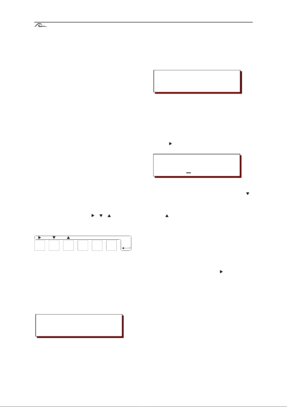
- Some keys have a double function. In
programming modes, the , ,
and # keys are used in combination with the
Enter key.
1. Press the Enter key.
To avoid accidental programming changes,
the key has to be held down for 4 seconds
before the basic values are released for
change.
The LCD display first shows the following
message.
After 4 seconds this changes to:
NOTE: Continue to hold down the Enter key for
functions 2 and 3.
2. At this point you can change the language of
the LCD display as follows:
Press ‘#’ key.
Use the key to move the cursor under the
abbreviation for the desired language.
3. You can move on to the first and
subsequent programming steps using the
key
4. You can move back to previous steps with
the key.
NOTE: The controller is now in programming
mode, and the Enter key should now be
released. To leave programming mode,
press the Enter key again. The controller will
also exit programming mode automatically
approximately 2 minutes after the last key
has been pressed.
5. The cursor is moved with the key.
Yes/No questions are answered by placing
the cursor under Y for Yes and N for No.
For numerical entries use the cursor to
select the digit to be changed.
6. The numerical settings selected with the
cursor can be changed within the preset
values by pressing the ‘#’ key.
NOTE: Programming must be carried out with
the filter in the service position. During a
regeneration there is no programming
possible.
English
D Nl E F Es I
Attention!
Programmechange
Start
Programmechange
#
Enter

ES2030 SV Display and modification of the basic settings 12
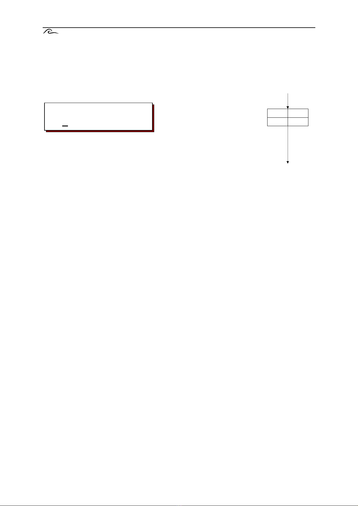
1. Filter switching
Single filter 1
If you enter ‘YES’ the system consists of 1 filter.
Single filter 2
If you enter ‘YES’ the system consists of 1 filter.
The ability to select between ‘Filter 1’ and ‘Filter 2’ allows a two filter system to be
reset quickly to single filter service (for repair work or low water demand).
Alternating service
A two filter system normally runs in alternating mode, with one filter supplying
treated water while the other filter is in reserve (standby) or is being regenerated.
Parallel service
If high output performance is required over a short period, a two filter system can
also be run in parallel. Here both filters supply treated water at the same time
except during a regeneration.
When the controller is programmed for parallel service, it can be switched back
and forward between alternating and parallel modes using the special function
‘Switching from parallel to alternate’.
Valve control for alternate service and parallel service can be entered at 4.1. For
this, the controller must first be programmed for alternate service (1.3 at Yes)
and then for parallel service (1.4 at Yes).
For parallel service you can determine whether the filters are to be regenerated
one after the other or at offset intervals.
If you select ‘Reg.Fi.1+2 Y/N’ both filters will be regenerated immediately one
after the other, since both filters are saturated.
For example: silica filter systems activated by time intervals or differential
pressure gauges.
NOTE: For water softening systems it must be ensured that brine is available
(reservoir tank or separate salt solution container).
If you select ‘Reg.Fi.1+2 Y/N’ only the saturated filter in service will be
regenerated. At this point the other filter still has 50% of its capacity.
For example: Quantity controlled water softening systems at high outputs.
Step no.: 1.1
SingleFilter1Y/N
Step no.: 1.2
SingleFilter2Y/N
Step no.: 1.3
2-tank alter.Y/N
Step no.: 1.4
Parallel servY/N
Step no.: 1.5
Reg.Fi.1+2 Y/N
Start
Yes No
1.1
2.1
Yes No
1.2
2.1
Yes No
1.3
1.8
Yes No
1.4
1.6
Yes No
1.5
1.8
2.1

ES2030 SV Display and modification of the basic settings 13
Series switching
Select series switching when the filters in a two filter system were set up in
series. For example: single flow partial desalination system with an H exchanger
and a Na exchanger.
For partial desalination systems the service life of the Na exchanger can be
several times longer than of the H exchanger. You can therefore enter a
regeneration ratio between 1:1 and 1:9.
For example, if you enter ‘relation 1:2’, the Na exchanger is only regenerated
after every second regeneration of the H exchanger.
Service valve
In ‘alternating service’ or ‘parallel service’, one filter continues to supply treated
water while the other is regenerating. If it too becomes saturated because the
amounts drawn off are too large, the message ‘capacity exceeded’ is displayed.
You can determine whether in that case the second valve is to stay open, with the
possibility that it will supply incompletely treated water (Main valve on Y/N) or
whether that valve should close too (Main valve on Y/N)., with the result that no
water flows to the user until the regeneration is completed.
NOTE: The programming setting ‘Stop in service’ (program step 4.1 – SP) is
activated if ‘Main valve on = N’) is set.
Step no.: 1.6
Series connecY/N
Step no.: 1.7
Relation 1:1
Step no.: 1.8
Main valve onY/N
Yes No
1.6
Ratio
1 :
1.7
1.1
1.4
2.1
2.1
Yes No
1.8
1.3 / 1.5
ES2030 SV Display and modification of the basic settings 14
2. Electrical control
The controller can be expanded with this relay by fitting the IF expansion card
(connector: OUT1 and connector OUT2).
ATTENTION: This program step can only be selected if the controller is fitted with
the IF2030 expansion card.
In this step you van select the outputs OUT1 (V7) and/or OUT2 (V8) for magnetic
valves.
(‘ – “ : No magnetic valve connected; “ | “ : Magnetic valve connected)
If an output is selected for valve function the corresponding step in step 15 will be
skipped.
Step no.: 2.1
V7- V8-
V7 V8
2.1
1.*
3.*

ES2030 SV Display and modification of the basic settings 15
3. Number of regeneration switch phases
Enter the number of regeneration switch phases for individual valve control.
(max. 9 phases).
4. Single valve control
This program step determines what valves are opened in what phase.
The first line of the LCD display shows valve numbers 1-8 (7 and 8 only
if programmed in step 2.1) during regeneration of filter 1 or filter 2. The
second line displays a phase, and under the numbers 1-8 the relevant
switch state in that phase..
Here ‘ | ‘ means relay activated and ‘-‘ means relay not activated.
In duplex installations a relay will be activated if for at least one filter
The relay is programmed at ‘|’.
In addition to the number of phases entered at program step 3.1, the
service position, the stop position in service and the stop position
during regeneration are
also programmed (display: SV, SP or HO phase).
The stop position in service can be activated by activating the input
‘STOP in service’ (program step 9), by ‘capacity exceeded’ (program
step 1.8), by ‘delayed regeneration’ (program step 6.5), by ‘minimum
regeneration distance’ (program step 8.4) and by ‘additional program
before regeneration’ (program step 16.3).
The stop position during regeneration can only be activated by
activating the input ‘stop during regeneration’ (program step 9).
Phase
Function V1 V2 V3 V4 V5 V6
1 Backwashing - - | | - X
2 Flushing (air) - - - - | X
3 Flushing (water) | - - - - X
4 ----
5 ----
6 ----
7 ----
8 ----
9 ---
SV Service position | | - - - -
SP Stop in service - - - - - -
HO Stop during regeneration - - - - - -
Fi1
1
2
3
4
5
6
7
8
1
2
3
4
5
6
7
8
9
SV
SP
HO
Fi2
1
2
3
4
5
6
7
8
1
2
3
4
5
6
7
8
9
SV
SP
HO
Unit 1 123456
Phase 1 |--||-
1.* / 2
Unit 2 123456
Phase 1 -|--||
4.1
Step no.: 3.1
Stage 4
Stages
3.1
5.1
4.2

ES2030 SV Display and modification of the basic settings 16
5. Regeneration times
The number of regeneration switch phases for individual valve control was set at
program step 3.1.
At this program step, enter the required times for each of the periods according to
the number of regeneration phases. No times are entered for the service and stop
positions.
Enter period number and the required time in the range from 1 to 990 minutes.
Examples where number of regeneration phases = 3 :
Backwashing period 1 : 10 minutes
Salting period 2 : 105 minutes
Washing out period 3 : 15 minutes
Step no.: 5.1
Time phase1: 10m
4.*
6.1
5.1
Time phase
1 m
2 m
3 m
4
m
5 m
6 m
7 m
8 m
9 m
ES2030 SV Display and modification of the basic settings 17
6. Delayed regeneration
A regeneration can be initiated at any time during the day. But it is often desirable
not to have a regeneration during production times, since for instance the water
pressure then may be insufficient for regeneration.
When ‘delayed regeneration’ is selected, a two filter system alternating service
will switching to the standby filter.
Select the day(s) when the function ‘delayed regeneration’ must be activated.
( “-“ = not activated; “|” = activated).
Enter the first time, after which no regeneration is to be initiated.
Enter the second time, after which regeneration is again permitted
Example 1: Time1 = 6:00 Time2 = 18:00
No regenerations are initiated automatically between 6 a.m. and 6 p.m. of the
same day.
Example 2: Time1 = 17:00 Time2 = 5:00
No regenerations are initiated automatically between 5 p.m. and 5 a.m. of the
following day.
With a 1 filter system, a 2 filter system connected in series and with a 2 filter
system operating in parallel with sequential regeneration. It can be determined
whether the service valve(or both service valves) should stay open until the
regeneration time entered (Main valve on Y/N) or should be shut immediately
(Main valve on Y/N).
If the service valve remains open, it should be ensured that the system can still
supply treated water until the regeneration time.
In the case of a 2 filter system operating in parallel with delayed regeneration it is
determined whether the service valve of the saturated unit remains open until the
delayed regeneration (Main valve on Y/N) or if the service valve closes and only
one filter is in service until the end of the delayed regeneration
(Main valve on Y/N)
A 2 filter system in alternating service always switches over to the standby filter,
and program step 6.5 cannot be selected.
NOTE: When ‘Main valve on Y/N’ the programmed setting ‘Stop in service’
(program step 4.1 – SP) is activated.
Step no.: 6.1
Time Delayed Y/N
Step no.: 6.3
Time1 6:00
Step no.: 6.4
Time2 18:00
Step no.: 6.5
Main valve onY/N
MoTuWeThFrSaSu
| | | | | | |
Yes No
6.1
Time 1
:
6.3
6.6
5.1
Time 2
:
6.4
Yes No
6.5
6.6
Mo
Tu
Fr
6.2
We
Th
Sa
Su
Table of contents
Other EWS Controllers manuals


