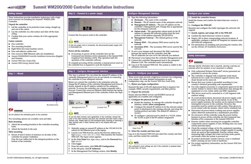
Extreme Networks Campus Controller E2122 User manual

Extreme Campus Controller™
Installation Guide
9036938-00 Rev AA
April 2021

Copyright © 2021 Extreme Networks, Inc. All rights reserved.
Legal Notice
Extreme Networks, Inc. reserves the right to make changes in specifications and other information
contained in this document and its website without prior notice. The reader should in all cases
consult representatives of Extreme Networks to determine whether any such changes have been
made.
The hardware, firmware, software or any specifications described or referred to in this document
are subject to change without notice.
Trademarks
Extreme Networks and the Extreme Networks logo are trademarks or registered trademarks of
Extreme Networks, Inc. in the United States and/or other countries.
All other names (including any product names) mentioned in this document are the property of
their respective owners and may be trademarks or registered trademarks of their respective
companies/owners.
For additional information on Extreme Networks trademarks, see: www.extremenetworks.com/
company/legal/trademarks
Open Source Declarations
Some software files have been licensed under certain open source or third-party licenses. End-
user license agreements and open source declarations can be found at: https://
www.extremenetworks.com/support/policies/open-source-declaration/

Table of Contents
Preface...................................................................................................................................4
Text Conventions.......................................................................................................................................................... 4
Documentation and Training.................................................................................................................................. 5
Getting Help....................................................................................................................................................................6
Subscribe to Product Announcements.....................................................................................................6
Providing Feedback.................................................................................................................................................... 6
E2122 Controller Overview................................................................................................. 8
E2122 back panel features........................................................................................................................................8
Hard Drive LED Indicator Patterns...................................................................................................................... 9
Controller Installation Guidelines....................................................................................10
Verify the Box Contents.......................................................................................................................................... 10
Mount the Controller.................................................................................................................................................. 11
Power Source and Power Supply Information............................................................... 12
Front Faceplate............................................................................................................................................................12
Connect to a Power Source................................................................................................................................... 12
Install a Power Supply.............................................................................................................................................. 14
Remove a Power Supply..........................................................................................................................................15
Replace a Power Supply..........................................................................................................................................15
Initial Network Connection and Configuration.............................................................. 17
Configure the Management Interface via Console Port...........................................................................17
Configure the Management Interface via Management Port................................................................19
Connect the Data Ports.................................................................................................... 20
Install a Transceiver............................................................................................................21
Regulatory Compliance Information...............................................................................23
Federal Communications Commission (FCC) Notice.............................................................................. 23
Industry Canada, Class A....................................................................................................................................... 23
Japan (VCCI) - Voluntary Control Council for Interference Class A ITE.........................................24
BSMI EMC Statement - Taiwan............................................................................................................................24
Hazardous Substances............................................................................................................................................24
European Waste Electrical and Electronic Equipment (WEEE) Notice......................................... 24
Supplement to Product Instructions................................................................................................................26
Index.................................................................................................................................... 27
Extreme Campus Controller™ iii

Preface
Read the following topics to learn about:
•The meanings of text formats used in this document.
•Where you can find additional information and help.
•How to reach us with questions and comments.
Text Conventions
Unless otherwise noted, information in this document applies to all supported environments for the
products in question. Exceptions, like command keywords associated with a specific software version,
are identified in the text.
When a feature, function, or operation pertains to a specific hardware product, the product name is
used. When features, functions, and operations are the same across an entire product family, such as
ExtremeSwitching switches or SLX routers, the product is referred to as the switch or the router.
Table 1: Notes and warnings
Icon Notice type Alerts you to...
Tip Helpful tips and notices for using the product
Note Useful information or instructions
Important Important features or instructions
Caution Risk of personal injury, system damage, or loss of data
Warning Risk of severe personal injury
4Extreme Campus Controller™

Table 2: Text
Convention Description
screen displays This typeface indicates command syntax, or represents information as
it is displayed on the screen.
The words enter and type When you see the word enter in this guide, you must type something,
and then press the Return or Enter key. Do not press the Return or
Enter key when an instruction simply says type.
Key names Key names are written in boldface, for example Ctrl or Esc. If you must
press two or more keys simultaneously, the key names are linked with a
plus sign (+). Example: Press Ctrl+Alt+Del
Words in italicized type Italics emphasize a point or denote new terms at the place where they
are defined in the text. Italics are also used when referring to
publication titles.
New information. In a PDF, this is searchable text.
Table 3: Command syntax
Convention Description
bold text Bold text indicates command names, keywords, and command options.
italic text Italic text indicates variable content.
[ ] Syntax components displayed within square brackets are optional.
Default responses to system prompts are enclosed in square brackets.
{ x | y | z } A choice of required parameters is enclosed in curly brackets separated
by vertical bars. You must select one of the options.
x | yA vertical bar separates mutually exclusive elements.
< > Nonprinting characters, such as passwords, are enclosed in angle
brackets.
... Repeat the previous element, for example, member[member...].
\ In command examples, the backslash indicates a “soft” line break.
When a backslash separates two lines of a command input, enter the
entire command at the prompt without the backslash.
Documentation and Training
Find Extreme Networks product information at the following locations:
Current Product Documentation
Release Notes
Hardware and software compatibility for Extreme Networks products
Extreme Optics Compatibility
Other resources such as white papers, data sheets, and case studies
Extreme Networks oers product training courses, both online and in person, as well as specialized
certifications. For details, visit www.extremenetworks.com/education/.
Preface Documentation and Training
Extreme Campus Controller™ 5

Getting Help
If you require assistance, contact Extreme Networks using one of the following methods:
Extreme Portal
Search the GTAC (Global Technical Assistance Center) knowledge base; manage support cases and
service contracts; download software; and obtain product licensing, training, and certifications.
The Hub
A forum for Extreme Networks customers to connect with one another, answer questions, and share
ideas and feedback. This community is monitored by Extreme Networks employees, but is not
intended to replace specific guidance from GTAC.
Call GTAC
For immediate support: (800) 998 2408 (toll-free in U.S. and Canada) or 1 (408) 579 2826. For the
support phone number in your country, visit: www.extremenetworks.com/support/contact
Before contacting Extreme Networks for technical support, have the following information ready:
•Your Extreme Networks service contract number, or serial numbers for all involved Extreme
Networks products
•A description of the failure
•A description of any actions already taken to resolve the problem
•A description of your network environment (such as layout, cable type, other relevant environmental
information)
•Network load at the time of trouble (if known)
•The device history (for example, if you have returned the device before, or if this is a recurring
problem)
•Any related RMA (Return Material Authorization) numbers
Subscribe to Product Announcements
You can subscribe to email notifications for product and software release announcements, Field
Notices, and Vulnerability Notices.
1. Go to The Hub.
2. In the list of categories, expand the Product Announcements list.
3. Select a product for which you would like to receive notifications.
4. Select Subscribe.
5. To select additional products, return to the Product Announcements list and repeat steps 3 and 4.
You can modify your product selections or unsubscribe at any time.
Providing Feedback
The Information Development team at Extreme Networks has made every eort to ensure the accuracy
and completeness of this document. We are always striving to improve our documentation and help
you work better, so we want to hear from you. We welcome all feedback, but we especially want to
know about:
•Content errors, or confusing or conflicting information.
Getting Help Preface
6Extreme Campus Controller™

•Improvements that would help you find relevant information in the document.
•Broken links or usability issues.
If you would like to provide feedback, you can do so in three ways:
•In a web browser, select the feedback icon and complete the online feedback form.
•Access the feedback form at https://www.extremenetworks.com/documentation-feedback/.
•Email us at documentation@extremenetworks.com.
Provide the publication title, part number, and as much detail as possible, including the topic heading
and page number if applicable, as well as your suggestions for improvement.
Preface Providing Feedback
Extreme Campus Controller™ 7

E2122 Controller Overview
E2122 controller hardware is a campus controller that supports two thousand standalone devices,
sixteen thousand users, and four hundred switches. It provides availability for up to four thousand
devices, thirty two thousand users, and eight hundred switches, with any client distribution between
controllers.
E2122 back panel features
Figure 1: E2122 back panel layout
Callout Description
1 Power supply module #1
2 Power supply module #2 bay for redundant power
supply (ordered separately)
3 Port 1 (Data Port 1) 1/10GbE, RJ45
4 Port 2 (Data Port 2) 1/10GbE, RJ45
5 VGA port (do not use)
6 RJ45 serial-A port
7 Admin, management port; 1GbE, RJ45
8 USB 2.0 or 3.0 ports
9 Not used
10 Port 3 (Data Port 3) 1/10 Gbps, SFP+
11 Port 4 (Data Port 4) 1/10 Gbps, SFP+
8Extreme Campus Controller™

Hard Drive LED Indicator Patterns
The hard drive has one LED indicator visible from the front of the system - a green LED for disk activity.
E2122 Controller Overview Hard Drive LED Indicator Patterns
Extreme Campus Controller™ 9

Controller Installation Guidelines
Verify the Box Contents on page 10
Mount the Controller on page 11
Details about the steps involved to safely install and configure the controller.
About This Task
Follow the steps to verify the controller box contents and safely install it.
Procedure
1. Verify the box contents.
2. Visually inspect the access point, the bracket, and any other optional accessories you have ordered
for physical damage.
If there is any damage, contact Extreme Networks Support.
3. Mount the controller on a rack or a table.
4. Connect the controller to a power source.
5. Install a power supply.
For power supply troubleshooting details, see remove a power supply or replace a power supply.
6. Configure the controller via console port or management port.
7. Connect the data ports.
8. Install a transceiver.
What to Do Next
Read and review the regulatory and compliance information.
Verify the Box Contents
When you receive the controller, ensure that the box contents are as follows:
•One E2122 Quick Reference
•One Extreme Campus Controller E2122 unit
•Two shipping lock screws
•One AC power cord bracket and retention strap kit
•One rack mounting kit
10 Extreme Campus Controller™

•One front panel faceplate
•One rail kit installation instruction sheet
Note
The power cord needs to be purchased separately for the respective deployment country.
They can be ordered at https://www.extremenetworks.com/powercords/.
Mount the Controller
Before You Begin
Caution
To minimize Electrostatic Discharge (ESD) damage to the devices, you must wear an antistatic
wrist strap while performing the following procedures.
About This Task
Mount the controller on a rack or a table.
Procedure
1. If you are installing the controller in a rack, read the Rail Kit Installation instruction sheet included
with the rack mounting kit.
2. Install the rails and mount the controller in the rack as instructed.
If you are table mounting the controller, ensure at least 6 cm of clearance on all sides of the
controller for proper ventilation.
Controller Installation Guidelines Mount the Controller
Extreme Campus Controller™ 11

Power Source and Power Supply
Information
Connect to a Power Source on page 12
Install a Power Supply on page 14
Remove a Power Supply on page 15
Replace a Power Supply on page 15
Connect to the power source at the back of the controller. The controller comes with two power
supplies support and distributes power load across both power supplies. Use the following topics to
connect the controller to a power source and to install, remove, and replace a power supply:
•Connect the controller to a power source
•Install a power supply
•Remove a power supply
•Replace a power supply
Front Faceplate
The controller comes with an optional front panel faceplate attached to the unit. You can monitor the
system status indicators with the faceplate in place.
Connect to a Power Source
Learn how to connect the controller to a power source.
About This Task
After installing the controller to a rack or to a table, connect the controller to a power source. To view
port information, see E2122 back panel features.
Procedure
1. Locate the power cord retention strap from the AC power cord bracket and cable clamp kit:
a. Insert the locking tab end of the retention strap into the receiver hole located to the right of
power supply module #1.
b. Adjust the slider of the retention strap to a desired position while pushing up the locking tab on
the bottom of the slider.
12 Extreme Campus Controller™

2. Connect the two AC power cables to power supplies 1 and 2.
These two power supplies combine to create an optional redundant power supply.
3. Optionally, wrap the slider strap over the power cord and lock it securely in place.
4. Plug the other end of the cables into grounded electrical outlets or to separate power sources such
as an uninterrupted power supply (UPS) or a power distribution unit (PDU).
5. Power on the controller.
The power button is on the front control panel as shown in E2122 front panel layout and front control
panel.
Figure 2: E2122 front panel layout
Callout Description
1 Hard disk drive bays
2 Front video controller
3 USB 2.0 or 3.0 ports
Note
For USB key storage only: Although the controller has 5 USB connectors (two on the front
panel and three on the back panel), only one USB connector can be in use at any one time.
Power Source and Power Supply Information Connect to a Power Source
Extreme Campus Controller™ 13

Figure 3: E2122 front control panel
Callout Description
1 System ID button with integrated LED
2 NMI button
3 Data Port 1 activity LED
4 Data Port 2 activity LED
5 Not used
6 Not used
7 System cold reset button
8 System status LED
9 Drive activity LED
10 Power button with integrated LED
Install a Power Supply
About This Task
Install a power supply to the controller for normal operation.
Procedure
1. Remove the insert from the chassis power supply bay.
2. Insert the power supply module into the power supply bay.
3. Push the power supply module into the bay until it locks into place.
Related Topics
Power Source and Power Supply Information on page 12
Connect to a Power Source on page 12
Remove a Power Supply on page 15
Install a Power Supply Power Source and Power Supply Information
14 Extreme Campus Controller™

Replace a Power Supply on page 15
Remove a Power Supply
About This Task
Remove a power supply before it needs to be replaced or if there is an issue with power connection to
the connector.
Procedure
1. Detach the power supply cord from the power supply that needs to be removed.
2. Pull the power supply module using the handle, while pushing the latching tab outward to
disengage the power supply from the unit.
Related Topics
Power Source and Power Supply Information on page 12
Connect to a Power Source on page 12
Install a Power Supply on page 14
Replace a Power Supply on page 15
Replace a Power Supply
The controller will support two power supplies, supplying hot-pluggable power redundancy. The system
distributes the power load across both power supplies to maximize eciency. When a power supply is
removed with the system powered on, the full power load is picked up by the remaining power supply.
Note
The system ships with just one power supply and you have the option to purchase the
additional redundant power supply (Ordering Part No. 30527 WS-PSI-1100W-01).
Important
The system requires one power supply to operate the system normally. Remove and replace
only one power supply at a time when a system is powered on.
Each power supply has a single bi-color LED to indicate power supply status, as described in power
supply status LED indicator patterns.
Table 4: Power supply status LED indicator patterns
Power supply condition Description
Output on and OK Green
No AC power to all power supplies O
AC present/only 12VSB on (PS o) or PS in cold
redundant state
1Hz blinking green
AC power cord unplugged or AC power lost. With
a 2nd PS in parallel still with AC input power
Amber
Power Source and Power Supply Information Remove a Power Supply
Extreme Campus Controller™ 15

Table 4: Power supply status LED indicator patterns (continued)
Power supply condition Description
Power supply warning events where PS continues
to operate - high temp, high power, high current,
and slow fan
1Hz blinking amber
Power supply critical event causing a shutdown,
failure, OCP, OVP, fan fail
Amber
Power supply firmware updating 2Hz blinking green
Related Topics
Power Source and Power Supply Information on page 12
Connect to a Power Source on page 12
Install a Power Supply on page 14
Remove a Power Supply on page 15
Replace a Power Supply Power Source and Power Supply Information
16 Extreme Campus Controller™

Initial Network Connection and
Configuration
Configure the Management Interface via Console Port on page 17
Configure the Management Interface via Management Port on page 19
You must configure the controller during initial use. There are two ways in which you can connect and
configure the controller:
•Configure the management interface via console port
•Configure the management interface via management port
Configure the Management Interface via Console Port
Learn how to configure the controller management interface using the console port.
About This Task
Configure the controller management interface via console port during initial setup.
Note
The E2122 must be upgraded to the latest Extreme Campus Controller firmware before
installing the controller on the network.
Procedure
1. Connect the serial port of the laptop to the E2122 console port.
If the laptop does not support RS232 interface then obtain a USB to RS232 converter cable, which
then connects to the RJ45-DB9F cable.
2. Using PuTTY, TeraTerm, or another terminal emulator, connect to the serial port connection.
Ensure that your serial connection is set properly:
•115200 baud
•8 data bits
•1 stop bit
•Parity none
•Flow control none
Extreme Campus Controller™ 17

3. Using the console session, perform the following:
a. At the password prompt, type user: admin
b. For the initial password, type: abc123
c. Press Enter
4. Read the configuration script paragraph.
The configuration script will walk you through configuring the following information:
•Admin Password
•Host Attributes Settings
•Time Settings
•SNMP Settings
•Data Plane Settings
5. At the end of each session, if you enter Yes, the next session will begin.
If you answer No, the session configuration is repeated.
6. Press ENTER.
After the final session is applied, the Appliance Post Installation Configuration Menu opens.
7. Type Ato apply settings and exit or a number for repeating the setup.
8. Connect to a port on which management access was enabled during the CLI Wizard Setup.
9. Open a web browser and type the following in the address bar: https://
Your_Mgmt_Ipaddress:5825.
The Extreme Campus Controller login screen is displayed.
10. Log in, as follows:
•Username: admin
•Password: abc123 or the password that was created when setting up the installation wizard
Note
An installation wizard is available to help configure the E2122 for new deployments. Refer
to the Extreme Campus Controller User Guide on the documentation site for more
information.
Related Topics
Configure the Management Interface via Management Port on page 19
Configure the Management Interface via Console Port Initial Network Connection and Configuration
18 Extreme Campus Controller™

Configure the Management Interface via Management Port
Learn how to configure the controller management interface using the management port.
About This Task
Configure the controller management interface via management port during initial setup. You can retain
the default IP address of the controller’s management interface if you do not intend to connect the
controller to your enterprise network.
Note
The E2122 must be upgraded to the latest Extreme Campus Controller firmware before
installing the controller on the network.
To connect the controller to your network:
Procedure
1. Connect a laptop to the management port of the controller.
2. Configure the Ethernet port of the laptop with a statically assigned unused IP address in the
192.168.10.0/24 subnet.
3. Open a web browser and type the following in the address bar: https://192.168.10.1:5825
(192.168.10.1 is the default IP address on the controller management port).
The Extreme Campus Controller login screen is displayed.
4. Log in, as follows:
•Username: admin
•Password: abc123
•Select Login
5. Complete the installation to configure the E2122 controller for new deployments.
6. Disconnect your laptop from the management port of the controller.
7. Connect the management port of the controller to the enterprise Ethernet LAN.
8. Log on to Extreme Networks.
The system is now visible to the enterprise network. Refer to the Extreme Campus Controller User
Guide on the documentation site for more information.
Related Topics
Configure the Management Interface via Console Port on page 17
Initial Network Connection and Configuration
Configure the Management Interface via Management
Port
Extreme Campus Controller™ 19

Connect the Data Ports
About This Task
Data ports 1 and 2 are 1/10 GbE RJ45 ports. To connect twisted pair cabling:
Procedure
1. Ensure that the device to be connected at the other end of the segment is powered on.
2. Connect the twisted pair segment to the controller by inserting the RJ45 connector on the twisted
pair segment into the desired RJ45 port.
3. Verify that a link exists by checking that the activity link LED is on (solid green or blinking green).
If the activity link LED is o, perform the following steps until it is powered on:
a. Verify that the cabling being used is Category 5 or better (Category 6 or better for 10 Gbps
connection), with an impedance between 85 and 111 ohms and a maximum length of 100 meters
(328 feet).
b. Verify that the device at the other end of the twisted pair segment is turned on and is properly
connected to the segment.
c. Verify that the RJ45 connectors on the twisted pair segment have the proper pinouts, and check
the cable for continuity.
4. If a link is not established, contact Extreme Networks Support.
20 Extreme Campus Controller™
Table of contents
Other Extreme Networks Controllers manuals