EX N' Flex EF-300 User manual

EX N’ FLEX
EF-300
Model EF-300
Leg/Arm Exerciser
Leg Exerciser
Arm Exerciser
Instructions for Use

Operating Instructions
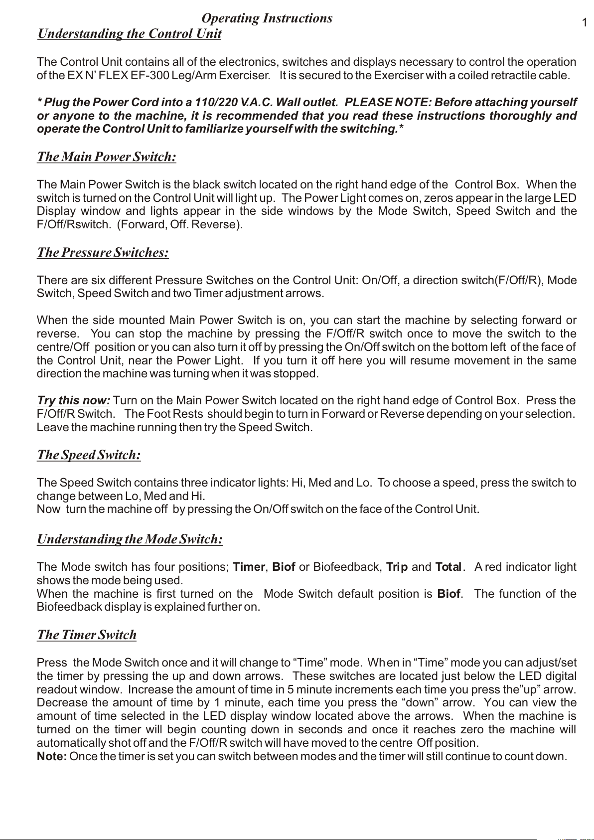
Understanding the Control Unit
The Control Unit contains all of the electronics, switches and displays necessary to control the operation
of the EX N’ FLEX EF-300 Leg/Arm Exerciser. It is secured to the Exerciser with a coiled retractile cable.
* Plug the Power Cord into a 110/220 V.A.C. Wall outlet. PLEASE NOTE: Before attaching yourself
or anyone to the machine, it is recommended that you read these instructions thoroughly and
operate the Control Unit to familiarize yourself with the switching.*
The Main Power Switch:
The Main Power Switch is the black switch located on the right hand edge of the Control Box. When the
switch is turned on the Control Unit will light up. The Power Light comes on, zeros appear in the large LED
Display window and lights appear in the side windows by the Mode Switch, Speed Switch and the
F/Off/Rswitch. (Forward, Off. Reverse).
The Pressure Switches:
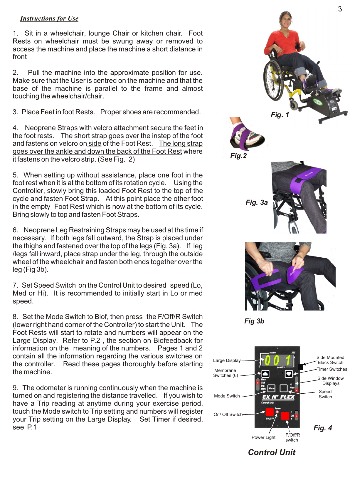
There are six different Pressure Switches on the Control Unit: On/Off, a direction switch(F/Off/R), Mode
Switch, Speed Switch and two Timer adjustment arrows.
When the side mounted Main Power Switch is on, you can start the machine by selecting forward or
reverse. You can stop the machine by pressing the F/Off/R switch once to move the switch to the
centre/Off position or you can also turn it off by pressing the On/Off switch on the bottom left of the face of
the Control Unit, near the Power Light. If you turn it off here you will resume movement in the same
direction the machine was turning when it was stopped.
Try this now: Turn on the Main Power Switch located on the right hand edge of Control Box. Press the
F/Off/R Switch. The Foot Rests should begin to turn in Forward or Reverse depending on your selection.
Leave the machine running then try the Speed Switch.
The Speed Switch:
The Speed Switch contains three indicator lights: Hi, Med and Lo. To choose a speed, press the switch to
change between Lo, Med and Hi.
Now turn the machine off by pressing the On/Off switch on the face of the Control Unit.
Understanding the Mode Switch:
The Mode switch has four positions; Timer, Biof or Biofeedback, Trip and Tot al . A red indicator light
shows the mode being used.
When the machine is first turned on the Mode Switch default position is Biof. The function of the
Biofeedback display is explained further on.
The Timer Switch
Press the Mode Switch once and it will change to “Time” mode. When in “Time” mode you can adjust/set
the timer by pressing the up and down arrows. These switches are located just below the LED digital
readout window. Increase the amount of time in 5 minute increments each time you press the”up” arrow.
Decrease the amount of time by 1 minute, each time you press the “down” arrow. You can view the
amount of time selected in the LED display window located above the arrows. When the machine is
turned on the timer will begin counting down in seconds and once it reaches zero the machine will
automatically shot off and the F/Off/R switch will have moved to the centre Off position.
Note: Once the timer is set you can switch between modes and the timer will still continue to count down.
1

Odometer “Total” Switch:
While still in Time mode, press the Mode Switch 3 times and you will change the mode ( the red indicator
light will move) to “Total” “Total” display acts as an odometer and logs the distance travelled. The total
cannot be reset and continually accumulates (mileage/kilometers for leg units).
Odometer “Trip” Switch:
Biofeedback Switch:
Press the Mode Switch again, or if the machine is turned off, turn it on and the red light will be in default
Biof position. “Biof “ or Biofeedback mode displays numbers on the digital display which fluctuate
between 0 and 235. These numbers indicate the effort require to move passive legs.
The Biofeedback mode is used to measure the User’s resistance and/or assistance. For example: if a
user has tone, stiffness, or spasticity in their legs, this would cause resistance and require the motor to
work harder to turn their limbs. As the user becomes more relaxed and flexible the “Biof” numbers will
decrease. This display enables someone with little or no feeling or voluntary movement in their limb(s) to
see the movement is making a difference.
If the user is using the machine actively or applying some of their own strength and assisting/overriding
the motor then the LED display will show a decrease in the “Biof” numbers. This shows the
User/Caregiver that the User is assisting the machine and building strength. Refer to P.3 for istructions
on using the machine actively.
Press the Mode Switch again and the red light will change the mode to “Trip”. “Trip” mode logs in meters
or yards in the U.S.A., the distance travelled for each session. Every Trip count, 1 revolution, equals 1
meter, 1000 M logged is equivalent to 1 Km. For U.S. Users, every Trip count,1 revolution, equals 1.094
yards. To save and add the accumulated revolutions from a session to the “Total” turn the
machine off using the On/Off Switch on the face of the Control Unit before turning off the main
power switch on the side.
2
0 0 10 0 1
Large Display
Membrane
Switches (6)
Mode Switch
On/ Off Switch
Power Light F/Off/R
switch
Side Mounted
Black Switch
Timer Switches
Side Window
Displays
Speed
Switch
Control Unit

Instructions for Use
1. Sit in a wheelchair, lounge Chair or kitchen chair. Foot
Rests on wheelchair must be swung away or removed to
access the machine and place the machine a short distance in
front
2. Pull the machine into the approximate position for use.
Make sure that the User is centred on the machine and that the
base of the machine is parallel to the frame and almost
touching the wheelchair/chair.
3. Place Feet in foot Rests. Proper shoes are recommended.
4. Neoprene Straps with velcro attachment secure the feet in
the foot rests. The short strap goes over the instep of the foot
and fastens on velcro on side of the Foot Rest. The long strap
goes over the ankle and down the back of the Foot Rest where
it fastens on the velcro strip. (See Fig. 2)
5. When setting up without assistance, place one foot in the
foot rest when it is at the bottom of its rotation cycle. Using the
Controller, slowly bring this loaded Foot Rest to the top of the
cycle and fasten Foot Strap. At this point place the other foot
in the empty Foot Rest which is now at the bottom of its cycle.
Bring slowly to top and fasten Foot Straps.
6. Neoprene Leg Restraining Straps may be used at ths time if
necessary. If both legs fall outward, the Strap is placed under
the thighs and fastened over the top of the legs (Fig. 3a). If leg
/legs fall inward, place strap under the leg, through the outside
wheel of the wheelchair and fasten both ends together over the
leg (Fig 3b).
7. Set Speed Switch on the Control Unit to desired speed (Lo,
Med or Hi). It is recommended to initially start in Lo or med
speed.
8. Set the Mode Switch to Biof, then press the F/Off/R Switch
(lower right hand corner of the Controller) to start the Unit. The
Foot Rests will start to rotate and numbers will appear on the
Large Display. Refer to P.2 , the section on Biofeedback for
information on the meaning of the numbers. Pages 1 and 2
contain all the information regarding the various switches on
the controller. Read these pages thoroughly before starting
the machine.
9. The odometer is running continuously when the machine is
turned on and registering the distance travelled. If you wish to
have a Trip reading at anytime during your exercise period,
touch the Mode switch to Trip setting and numbers will register
your Trip setting on the Large Display. Set Timer if desired,
see P.1
0 0 10 0 1
Large Display
Membrane
Switches (6)
Mode Switch
On/ Off Switch
Power Light F/Off/R
switch
Side Mounted
Black Switch
Timer Switches
Side Window
Displays
Speed
Switch
Control Unit
Fig. 1
Fig.2
Fig. 3a
Fig 3b
Fig. 4
3

10. Rotate one revolution to ensure that the unit is positioned
correctly. With correct positioning there should be a slight
bend in the knee when the foot is furthest away. This bend
prevents the knee from hyperextending. If the machine is
too close the back of the Foot Plates may touch the front of
the chair or wheelchair; if this is the case, you are too close.
Shut the machine off and adjust the machine accordingly.
Once any adjustments have been made, you are ready to
proceed with your exercise program.
11. Press F/Off/ R switch to restart Machine
12. Relax, sit back and let the machine rotate your legs. If
higher speed is required, adjust Speed Control Switch. If
Active Exercise is desired, refer to page 3 on Biofeedback
display.
13. For best results time should be divided between Forward
and Reverse motion Reverse Motion is achieved by use of
the F/Off/R switch.
14.
15. Remove Foot Straps and unplug from wall.
16 To use as an Arm Exerciser the user must have sufficient
strength to grip the Hand Grip or use the Hand Strap to secure
the hand in place, (Fig.7a & 7b).
17. Lift machine onto a table. Turn the Foot rests over so that
the flat undersurface is facing up. The Hand Grip is on this
surface. The flat surface serves as an arm/shoulder support
to prevent the shoulder sagging during exercise. The long
Arm Strap can be folded back over the wrist/forearm area and
secured to the velcro. If this strap or the Hand Strap is
required, the User will need assistance to operate the
machine. Once hands are in place turn on the machine
The Arms rotate in a circular motion (ergometer style) and
you may use your own upper body strength to assist the
machine.
18. Once the exercise session is complete, turn off the
machine as in item 14 and remove any straps that may have
been required.
To Turn Off, switch to Off on the F/Off/R switch then Red
On/Off Switch. This will turn off all displays and store the
data from Trip to Total on the touch pad. It is necessary to
turn off power Switch before turning off Side Mounted
switch or the Trip Data from the current session will not
be stored.
This is useful for people
with short legs or extreme tone/spasm. This permits a
smaller range of movement before working up to full
amplitude/range of motion.
NB. The Crank Arm is provided with an Inner Hole to
allow for a reduced amplitude.
Lifting/Carrying
Handles
Retractile
Cable Rubber Leg
Tips
Control
Unit
Hand
Grips
Foot
Rest
Foot
Straps
Crank Arm
2 Amplitudes
4.
Fig.5
Arm Rest
Hand Strap
Arm Strap
Fig.6
Fig.7a
Fig. 7b
Control Unit

Second Closure
of Hand Strap
(after hand is placed
around Gripping Post)
First Closure
of Hand Strap
Fig. #1
Attach the neoprene Hand Strap to the wrist of the
affected arm and fasten around the wrist with velcro
closures, (Fig. #1).
Place the hand onto the Hand Grip. Work the
fingers around the Grip. Pass the second closure
of the Hand Strap under the Hand Grip, Fig #2. Pull
over the Hand Grip and hand and continue pulling
the strap and attach it to the exposed velcro on the
wrist, Fig #3. The strap will prevent the hand, which
may have little or no gripping power, from slipping off
the Hand Grip during exercise. The affected hand
may need some assistance in holding onto the Hand
Grip while attaching the strap. If additional arm
support is required , the leg straps may be brought
from the other side and fastened over the arm and
secured on the velcro on the Foot Rest. See P.4,
Fig. 7a
1.
Second Closure
of Hand Strap
(after hand is placed
around Gripping Post)
Velcro
Hand
Grip
Foot
Rest
Foot
Strap
Hand
Strap
Hand
Grip
Foot
Rest
FIG. #2
Fig.#3
2.
Attaching the Hand Strap
P. 5

As with any exercise program, the best results are achieved with a gradual approach. (Resist the
temptation to spend more than five minutes on the machine to start with). Slow speed is a good way to
start. In extreme cases, only one or two revolutions may be achieved because of muscle/joint
resistance or spasm. Sometimes by switching between Forward and Reverse and the speed switch set
to High, it is possible to achieve several partial revolutions. With repeated sessions this should result in
increased flexibility in the muscles and tendons to a point where full revolutions should be achieved.
Any excessive resistance will show on the Biofeedback display as high numbers. As flexibility improves,
the numbers shown on the Biofeedback will decrease. Once flexibility is regained and no discomfort is
experienced the following day, the amount of time on the machine may be increased one minute per
session to a maximum of 30 minutes per session. The time should be equally divided between Forward
and Reverse. The EX N’ FLEX may be used for more than one session per day. If discomfort is
experienced as a result of unaccustomed exercise, discontinue use of the machine until discomfort
subsides, then resume program.
**** To assure that the legs are not over extended, make sure that the machine is close enough that the
User has a partial bend in the arm at all times during use.
Note:
When excessive resistance occurs the machine will stall and after 8 seconds. To restart machine, press
F/Off/R Switch
How Long Should I Stay on the EX N’ FLEX ?
6.

Part# Item Part # Item
EF-300 Parts List
This product is warranteed to be free from defects in
material and workmanship for a period of 1 year from the
date of purchase or lease.
Important: This warranty does not cover damage
resulting from an accident, misuse or abuse, lack of
reasonable care, the affixing of unauthorized
attachments, loss of parts or subjecting the device to
other than specified voltage. (Read directions and
instructions carefully).
If malfunction occurs, do not use the unit.
To ensure prompt service contact EX N’ FLEX by phone
or email. We will repair, replace the machine or send
replacement parts (our option) at no charge to you.
If the warranty has expired or other terms are not met
there will be a charge for any repairs, parts or shipment
required.
Contact:
Tecogics Scientific Limited
2430 Magnus Avenue,
Ottawa, ON K1G 1J8 Canada
Toll Free: 1(888)298-9922
Free Phone: U.K. 0800 032 2814
Ph: (613)733-2988 Fax: (613)733-4250
website: www.exnflex.com
Save this warranty for your records
One year limited Warranty
3000L/A Axel/ Main Bearing Assembly 3015L/A Handles
3001L/A Cover, Top 3016L/A Hanger Brackets only
3002L/A Cover, Base Plate 3017L/A Hanger Bracket Hand Grip
3003L/A Bronze Bushings 3018L/A Leg Strap 40”
3004L/A Cable Harness 3019L/A Leg Strap 48”
3005L/A Chain 3020L/A Main Frame
3006L/A Control Unit 3021L/A Motor
3007L/A Crank Arm 3022L/A Pontoon
3023L/A Pontoon Plastic Foot3008L/A Decal EX N’ FLEX
3009L/A Decal (Leg/Arm Exerciser) 3024L/A Power Cord
3010L/A Foot Plastic 3025L/A Power Supply
3011L/A Foot Plate 3026L/A Rubber Feet (ea.)
3012L/A Foot Plate/ Hanger Bracket 3027L/A Shoulder Bolt (Foot Plate)
Ass’y(set) (no Crank Arm)
3013L/A Foot Straps(Pair)
3014L/A Foot Straps-XL (Pair)
7
Table of contents
Other EX N' Flex Fitness Equipment manuals