EX N' Flex EF-250 User manual


18-2596 Edinburgh Place
Ottawa, On, Canada
K1B 5M1
1-613-733-2988 pg. 2
Rev: 08-10-2020
Contents
Introduction...................................................................................................................3
Understanding and Deploying the Locking Mechanism.................................................3
Base Handle Position #1A & #1B......................................................................................................3
Base Handle Position #2 ...................................................................................................................4
Unlock Mechanism:...........................................................................................................................4
Operating Instructions...................................................................................................4
Powering Up Your EX N’ FLEX .........................................................................................................4
Understanding the Control Unit .........................................................................................................5
The Main Power Switch:....................................................................................................................5
The Pressure Buttons:.......................................................................................................................5
The Speed Button:.............................................................................................................................6
Understanding the Mode Button:.......................................................................................................6
The Timer Button...............................................................................................................................6
Odometer “Total” Button:...................................................................................................................7
Odometer “Trip” Button:.....................................................................................................................7
Biofeedback Button: ..........................................................................................................................7
Control Unit...................................................................................................................8
How Long Should I Stay on my EX N’ FLEX ? ............................................................10
EF-250 Parts List........................................................................................................11
Warning
1. We strongly recommend consulting with a professional to ensure the
Passive Activity Range of Motion Therapy provided by this EX N’ FLEX device
provides the desired positive benefits through a physiotherapy program.

18-2596 Edinburgh Place
Ottawa, On, Canada
K1B 5M1
1-613-733-2988 pg. 3
Rev: 08-10-2020
2. As with any physiotherapy device, we strongly recommend that the user is
supervised throughout their activity.
Introduction
The EX N’ FLEX Model EF-250 has been designed for people who have a wide range of mobility
problems from the result of illness or accident. It provides a sustained, predictable Range of Motion
therapy (ROM) to Muscles, Joints and Tendons for individuals who face a future with little or no
movement. The movement provided is both physically and psychologically beneficial and may be
used as an adjunct to regular physiotherapy, or where physiotherapy is not available. Thank you for
choosing Ex N’ Flex!
Understanding and Deploying the Locking Mechanism
Base Handle Position #1A & #1B
Position #1A: The Base Handle (Locking Mechanism) stands up in a
vertical position away from the top of the base and the casters are
touching the floor. In this position, the machine can be freely moved
or transported.
Position #1B: The Base Handle has been pushed forward up onto
the base by gripping the lower part of the Base Handle closest to the
floor. Once in place it should lay flat on the top of the base. This lowers
the rubber tipped legs and the casters are now suspended off the floor
under the base cover.
Adjustment to the user's wheelchair or the machine may be necessary
to attain the best positioning. See P.7 (#1-5) for positioning.
*** Try placing yourself in the machine initially. *** This
experiment will permit you to judge a more accurate placement for
each individual. There should be some bend in the knee when the
Foot Rests reach the furthest point of extension.
Locking Lever
Base Handle
4
Casters
Located
under Base
Base Frame
Locking Lever
Base Handle
4
Rubber
Stoppers
Base Frame
Position #1B
Position #1A

18-2596 Edinburgh Place
Ottawa, On, Canada
K1B 5M1
1-613-733-2988 pg. 4
Rev: 08-10-2020
Base Handle Position #2
Once the Base Handle is in position on top of the Base Cover,
swing the Locking Lever over the top of the Base Handle. The machine
is now locked into position.
Unlock Mechanism:
To return the base to its casters; grip the black locking lever knob and
swing the lever off and away from the Base Handle. The Base Handle
(locking mechanism), can now be pulled down towards the floor raising
the legs and allowing the casters to touch the floor.
Operating Instructions
Powering Up Your EX N’ FLEX
Plug the Power Cord into a 110/220 V.A.C. Wall outlet. Turn on the control unit by using the black
switch located on the upper right hand side.
Locking Lever
Base
Handle
4
Rubber
Stoppers
Base Frame
Position #2

18-2596 Edinburgh Place
Ottawa, On, Canada
K1B 5M1
1-613-733-2988 pg. 5
Rev: 08-10-2020
PLEASE NOTE: Before attaching
yourself or anyone to the machine, it is
recommended that you read these
instructions thoroughly and operate the
Control Unit to familiarize yourself with
device.
Understanding the Control Unit
The Control Unit contains all of the
electronics, switches and displays
necessary to control the operation of the
EX N’ FLEX EF-250 device. The
controller is secured to the device by
means of two screws and plugs into a
connector. It can be easily removed for
servicing or replacement.
The Main Power Switch:
The Main Power Switch is the black switch located on the right-hand edge of the Control Box.
When the switch is turned on the Control Unit will light up. The Power Light will come on, zeros
will appear in the large LED Display window, and red lights appear in the side windows by the
Mode Switch, Speed Switch, and the F/Off/R switch. (Forward, Off. Reverse).
The Pressure Buttons:
There are six different pressure buttons on the Control Unit: On/Off, a direction of travel
button(F/Off/R), Mode button, Speed button and two Timer adjustment arrows.
1
0
0
0
0
1
Large
Display
Membrane
Buttons(6)
Mode Button
On/ Off
Button
Power
Light
F/Off/R
Butto
n
Side Mounted
Black Switch
Timer Button
Side
Window
Displays
Speed
Button

18-2596 Edinburgh Place
Ottawa, On, Canada
K1B 5M1
1-613-733-2988 pg. 6
Rev: 08-10-2020
When the side mounted Main Power Switch is on, you can start the machine by selecting forward
or reverse. You can stop the machine by pressing the F/Off/R button once which will transition
the device into the centre/Off position. You can also turn it off by pressing the On/Off button on
the bottom left of the Control Unit near
the Power Light.
Try this now: Turn on the Main
Power Switch located on the right-
hand edge of Control Box. Press the
F/Off/R button. The Foot Rests
should begin to turn in Forward or
Reverse depending on your selection.
Leave the machine running then try
the Speed button.
The Speed Button:
The Speed Button contains three
indicator lights: Hi, Med and Lo. To choose a speed, press the switch to change between Lo, Med
and Hi.
Now turn the machine off by pressing the On/Off Button on the face of the Control Unit.
Understanding the Mode Button:
The Mode button has four positions: Timer, Biof (Biofeedback), Trip and Total. A red indicator
light shows the mode being used.
When the machine is first turned on the Mode button default position is Biof. The function of the
Biofeedback display is explained further on. (See Page 6).
The Timer Button
Press the Mode button once and it will change to “Time” mode. When in “Time” mode you can
adjust/set the timer by pressing the up and down arrows. These buttons are located just below
the LED digital readout window. Increase the amount of time in 5-minute increments each time
you press the “up” arrow. Decrease the amount of time by 1 minute, each time you press the
“down” arrow. You can view the amount of time selected in the LED display window located above
the arrows. When the machine is turned on the timer will begin counting down in seconds, and
once it reaches zero the machine will automatically shut off. The “F/Off/R”button will have moved
to the centre “Off” position.
Note: Once the timer is set you can switch between modes and the timer will continue to count
down.
1
0
0
0
0
1
Large Display
Membrane
Buttons(6)
Mode Button
On/ Off Button
Power Light
F/Off/R
Button
Side Mounted
Black Switch
Timer Button
Side Window
Displays
Speed
Button

18-2596 Edinburgh Place
Ottawa, On, Canada
K1B 5M1
1-613-733-2988 pg. 7
Rev: 08-10-2020
Odometer “Total” Button:
While still in Time mode, press the Mode button 3 times and you will change the mode (the red
indicator light will move) to “Total”. The “Total” display acts as an odometer and logs the distance
travelled. The total cannot be reset and continually accumulates (mileage/kilometers for leg
units), much like the odometer on a car.
Odometer “Trip” Button:
Press the Mode button again and the red
light will change the mode to “Trip”.
“Trip” mode logs in meters or yards in
the U.S.A. the distance travelled for
each session. Every Trip count equals
1 meter. Every 1000 meters logged is
equivalent to 1KM. For U.S. Users,
every Trip count equals 1.1 yards. To
save and add the accumulated
revolutions from a session to the
“Total” turn the machine off using the
On/Off button on the face of the
Control Unit before turning off the main
power switch on the side.
Biofeedback Button:
Press the Mode Button again, or if the machine is turned off, turn it on and the red light will be in
default Biof position. “Biof “or Biofeedback mode displays numbers on the digital display which
fluctuate between 0 and 235. These numbers indicate the effort require to move passive legs.
The Biofeedback mode is used to measure the User’s resistance and/or assistance. For
example: if a user has tone, stiffness, or spasticity in their legs, this will cause resistance and
require the motor to work harder to turn their limbs. As the user becomes more relaxed and
flexible the “Biof” numbers will decrease. This display enables someone with little or no feeling
or voluntary movement in their limb(s) to see the movement is making a difference.
1
0
0
0
0
1
Large Display
Membrane
Buttons(6)
Mode Button
On/ Off Button
Power Light
F/Off/R
Button
Side Mounted
Black Switch
Timer Button
Side Window
Displays
Speed
Button

18-2596 Edinburgh Place
Ottawa, On, Canada
K1B 5M1
1-613-733-2988 pg. 8
Rev: 08-10-2020
If the user is using the machine actively or applying some
of their own strength and assisting/overriding the motor,
then the LED display will show a decrease in the “Biof”
numbers. This shows the User/Caregiver that the User is
assisting the machine and building strength.
Control Unit
Instructions for Use
1. Sit in a wheelchair, lounge Chair or kitchen chair.
Foot Rests on wheelchair must be swung away or removed
to access the machine. Either wheel the machine into the
chair or position the chair a short distance in front of the
machine, ie:4”-5”.
2. Grip the Positioning Handle on the front of the
machine and pull the machine into the approximate position
for use. Make sure that the User is centred on the machine
and that the base of the machine is parallel to the frame of the
wheelchair/chair.
3. Place Feet in Foot Rests. Proper shoes are
recommended. It may be necessary to adjust the height of the
machine for the foot does properly fit on the Foot Rest (ie: the
legs are too short or the wheel chair cushion istoo high.) Height
adjustment is obtained by rotating the Height Adjustment knob
on the back of machine. Turn counter clockwise to loosen the
clamp, raise to desired height, turn clockwise to tighten. The
upper unit can be raised 12” above the base (see P.8, Fig.5
Detail A).
4. Neoprene Straps with Velcro attachment secure the feet
in the foot rests. The short strap goes over the instep of the
foot and fastens on Velcro on the side of the Foot Rest. The
long strap goes over the ankle and down the back of the Foot
Rest where it fastens on the Velcro strip. (See Fig. 2)
5. Neoprene Leg Restraining Straps may be used at this
time if necessary. If both legs fall outward, the Strap is placed
under the thighs and fastened over the top of the legs (Fig. 3a).
If leg /legs fall inward, place strap under the leg, through the outside wheel of the wheelchair and
fasten both ends together over the leg (fig.3b)
Figure 3A
Strap
Leg Restraining
Strap
Figure 1
Figure 2
Figure 3B

18-2596 Edinburgh Place
Ottawa, On, Canada
K1B 5M1
1-613-733-2988 pg. 9
Rev: 08-10-2020
6. Set Speed button on the Control Unit to desirespeed (Lo,
Med or Hi). It is recommended to initially start in Lo or med
speed.
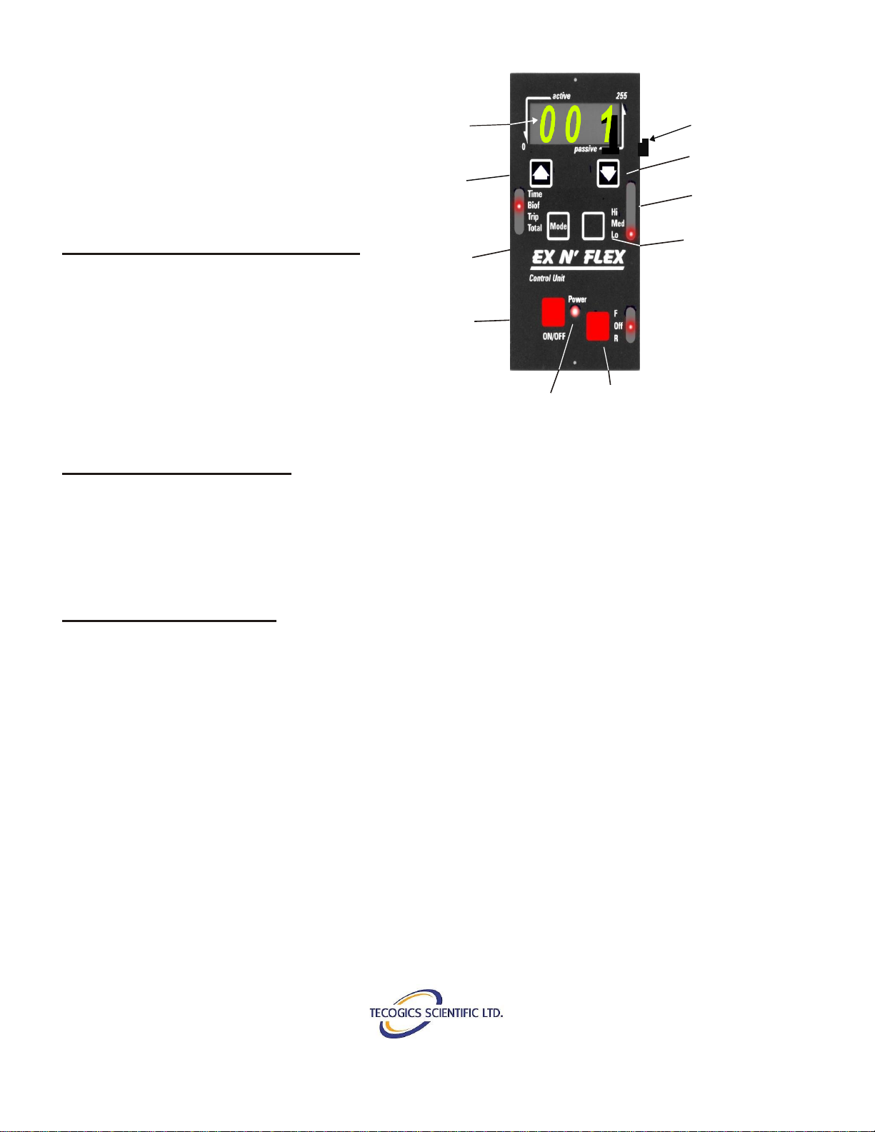
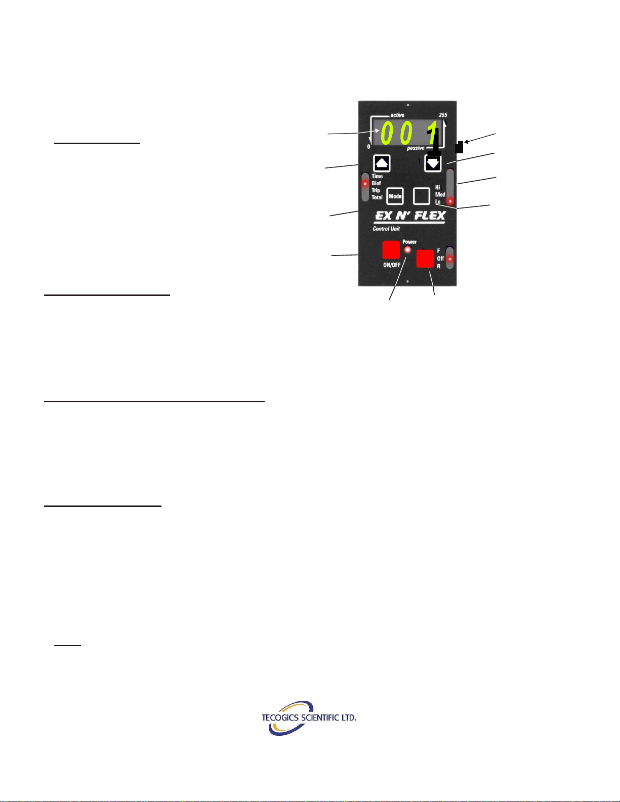
7. Set the Mode button to Biof, press the
F/Off/R button (lower right hand corner of the
Controller) to start the Unit. The Foot Rests will
start to rotate and numbers will appear on the
Large Display. Refer to P.6 , the section on
Biofeedback for information on the meaning of
the numbers. Pages 4-6 contain all the
information regarding the various switches on the
controller. Read these pages thoroughly before
starting your machine.
8. The odometer is running continuously
when the machine is turned on and is registering
the distance travelled. If you wish to have a Trip
reading at anytime during your exercise period,
Select the Trip Display. Set Timer if desired, see
P.5.
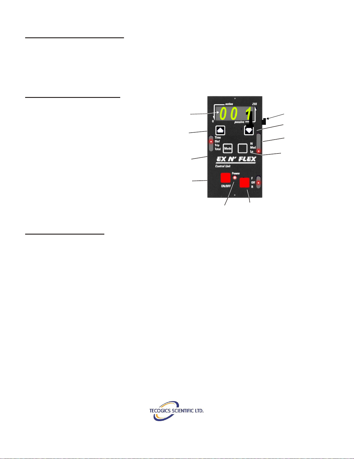
10.Press F/Off/R switch to commence your
exercise program.
11.Relax, sit back, and let the machine do the
work. If higher speed is required, press mode
switch. If some active exercise is desired
refer to the section on Biofeedback display,
Page 6.
12.For best results, time should be equally
divided between Forward and Reversemotion.
Reverse motion is achieved by use of the F/Off/R button.
13.To Turn Off, button to Off on the F/Off/R button then Red On/Off button. This will turn off all
displays and store the data from Trip to Total on the touch pad. It is necessary to turn off
power button before turning off the Side Mounted switch or the Trip Data from the current
session will not be stored.
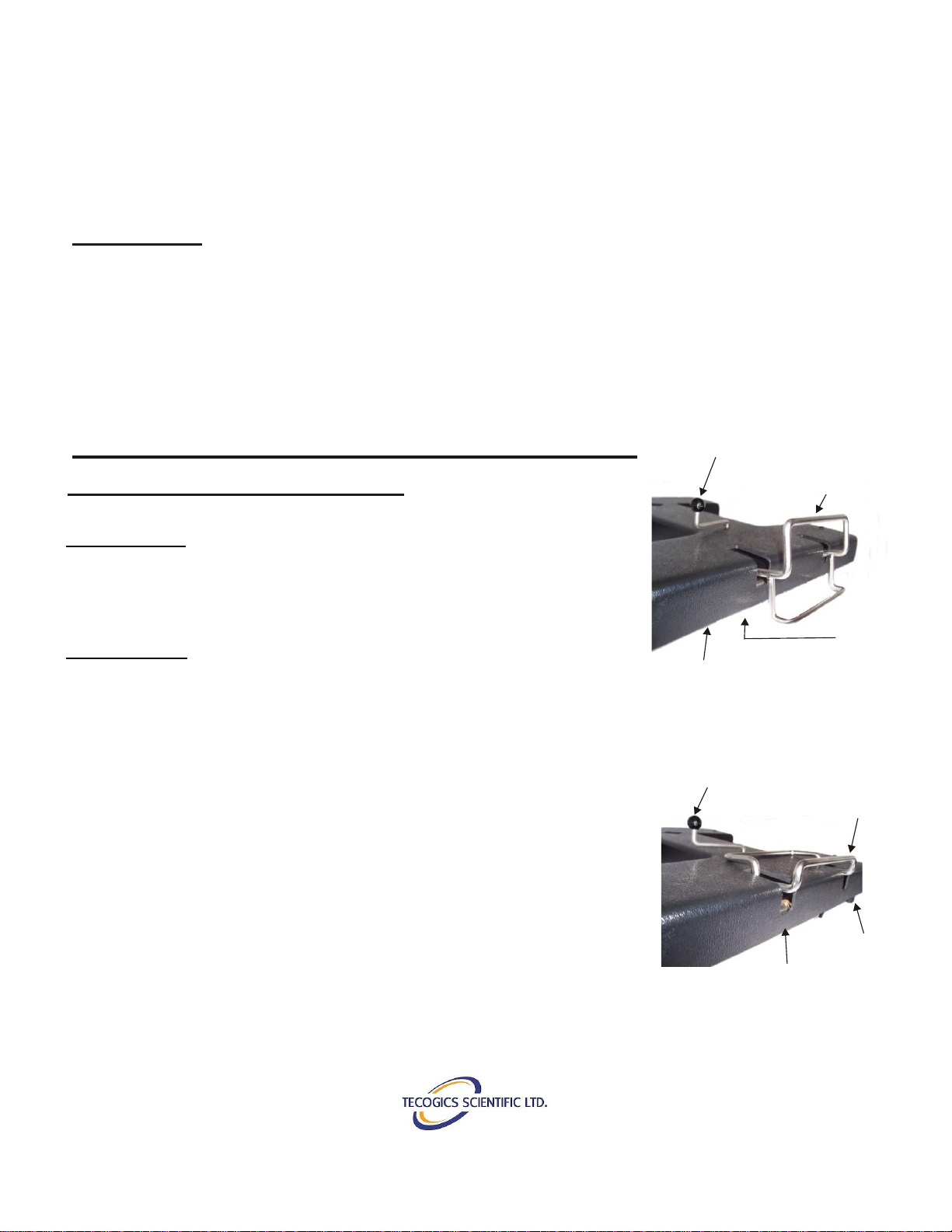
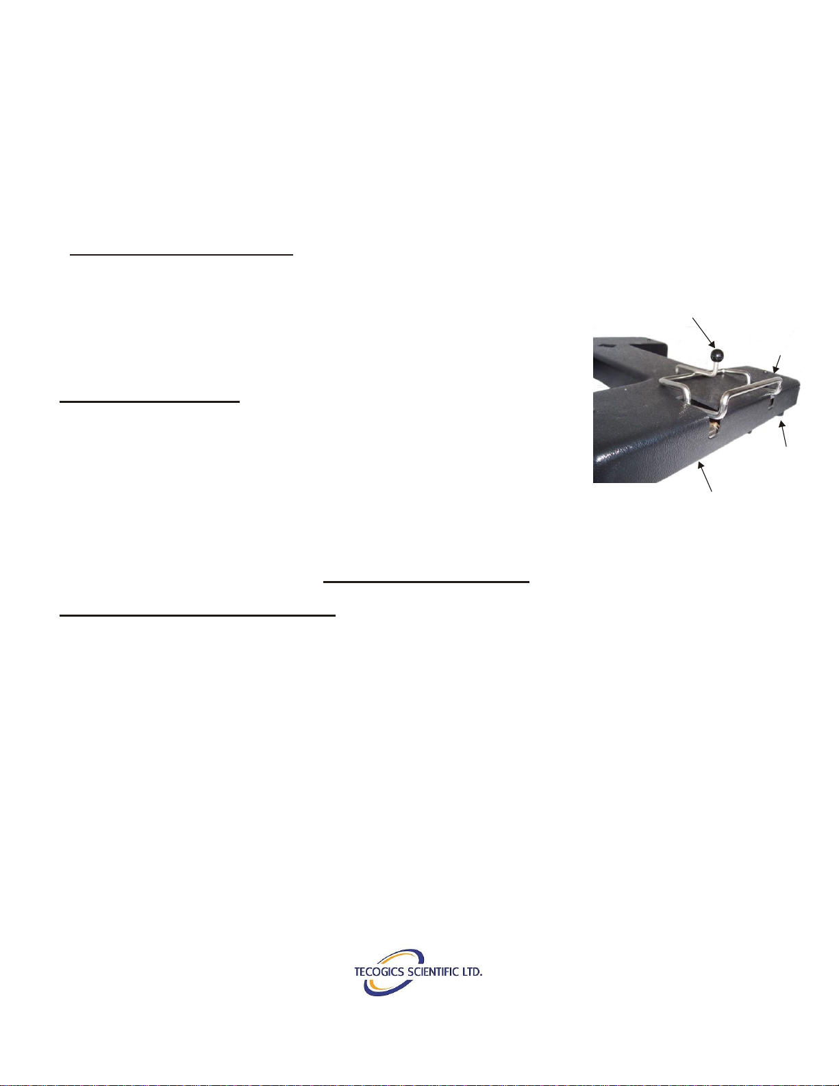
14.Remove Foot Straps, swing Locking Lever free of Locking Mechanism and push machine away.
If you wish to leave the machine in position for easy access from your wheelchair, unlock the
wheelchair and push away from the machine.
NB. The Crank Arm is provided with an Inner Hole to allow for a reduced amplitude.
This is useful for people with short legs or extreme tone/spasms. This permits a
smaller range of monition (ROM) before working up to full amplitude/range of motion.
Foot Straps
Foot Rests
Transporting Handle
Power Cord
Locking Lever
Control Unit
Base
Height
Adjustment
Knob
Height
Adjustment
Bar
Positioning
Handle
Figure 5: Detail A
Figure 5: Fully Assembled EF-250

18-2596 Edinburgh Place
Ottawa, On, Canada
K1B 5M1
1-613-733-2988 pg. 10
Rev: 08-10-2020
How Long Should I Stay on my EX N’ FLEX ?
As with any exercise program, the best results are achieved with a gradual approach. (Resist
the temptation to spend more than five minutes on the machine to start with). Slow speed is a
good way to start. In extreme cases, only one or two revolutions may be achieved because of
muscle/joint resistance or spasm. Sometimes by switching between Forward and Reverse and
the speed switch set to High, it is possible to achieve several partial revolutions. With repeated
sessions this should result in increased flexibility in the muscles and tendons to a point where full
revolutions should be achieved. Any excessive resistance will show on the Biofeedback display
as high numbers. As flexibility improves, the numbers shown on the Biofeedback will decrease.
Once flexibility is regained and no discomfort is experienced the following day, the amount of time
on the machine may be increased one minute per session to a maximum of 30 minutes per
session. The time should be equally divided between Forward and Reverse. The EX N’ FLEX
may be used for more than one session per day. If discomfort is experienced as a result of
unaccustomed exercise, discontinue use of the machine until discomfort subsides, then resume
the program.
**** To assure that the legs are not over extended, make sure that the machine is close enough
that the User has a partial bend in the legs at all times during use.
Note:
When excessive resistance occurs, the machine will stall and stop moving after 8 seconds. To
restart the machine, press the F/Off/R Switch.

18-2596 Edinburgh Place
Ottawa, On, Canada
K1B 5M1
1-613-733-2988 pg. 11
Rev: 08-10-2020
EF-250 Parts List
Below you will find a condensed part list for you Ex N’ Flex machine. All the parts listed are
available should you need to replace anything that become worn or broken over time. We also
have a complete inventory of replacement and refurbished parts. Simply contact us and we will
be happy to assist you in any way we can!
Part #
Item
A2005
Axel Assembly
A2002
Base Assembly
E10020
Power Cord 10’ Right Angle
A2008
Power Supply Assembly
H00023
Casters
A2004
Control Unit Assembly
*Note: Contact us at Ex N’ FLEX to inquire about any replacement parts. Depending on the age of
the device, parts may have been upgraded or modified. We will be happy to assist you in finding the
appropriate parts for your device.
**Note: Part A2013 ‘Consumable Strap Package’ includes a complete set of new straps & stoppers
for your EF-250. It is recommended that these components be changed every 2 years or when worn.
Part #
Item
A2013
Consumable Strap Package
P10005
Foot Plate (Left)
P10006
Foot Plate (Right)
A2015
Height Adjustment Assembly
A2016
Crank Arm Assembly
A2003
Foot Plate Assembly
Tecogics Scientific Ltd
18-2596 Edinburgh
Place
Ottawa, Ontario,
Canada K1B 5M1
+1-613-733-2988
1-833-396-3539
Table of contents