Exalt EX-4.5r GigE Programming manual

201872-004
2016-05-26
EX-r Series GigE
Digital Microw ave Radios
I nstallation and Management Guide
Models:
EX-4.5r GigE
EX-4.5r-c GigE
EX-5r GigE
EX-5r-c GigE

Legal Notice
The information contained herein is the property of Exalt Wireless, Inc. (“Exalt”) and is supplied
without liability for errors or omissions. No part of this document may be reproduced, in any form,
except as authorized by contract or other written permission from the owner.
Any brand names and product names included in this manual are trademarks, registered trademarks, or
trade names of their respective holders.
The contents of this document are current as of the date of publication. Exalt reserves the right to
change the contents without prior notice.
The publication of information in this document does not imply freedom from patent or other rights of
Exalt or others.
© 2015 Exalt Wireless Inc. All rights reserved.
The Exalt logo, ExtremeAir, and ExploreAir are registered trademarks of Exalt Wireless, Inc.
Open-Source License Information
Per the terms of your Exalt Limited Hardware Warranty, Software License, and RMA Procedures
Agreement with Exalt Wireless, Inc. and/or its subsidiaries, certain Third Party Software may be
provided with and as part of the Exalt products provided to you, and any such Third Party Software
files provided are governed by the terms of their separate Third Party Licenses, which licenses give
you at least the license rights licensed to you in the Exalt End User Agreement and may give you
additional license rights as to the Third Party Software, but only with respect to the particular Third
Party Software to which the Third Party License applies.
The Exalt Products may include or be bundled with some or all of the following third party software.
Copies of the copyright notices and license agreements for any or all of these may be requested by
Open Source Code License Agreement Website
Embedded Linux - OS
U-Boot
Boot Code. Both licensed under GPL Version 3 www.gnu.org
www.sourceforge.net
Busy Box Linux Commands. Licensed under GPL Version 2 www.gnu.org and
www.busybox.net
Scew Expat Wrapper. Licensed under LGPL Version 3 www.gnu.org
OpenSSL SSL Web Access. Licensed under dual license www.openssl.org
Net-SNMP SNMP Agent. Licensed under NetSNMP (see
Copyright Notices)
Dropbear SSH 2 Server; Expat - XML Parser; BarelyFitz –
Java Script Tabifier; and Flotr – Java Script Plotting
Library. All four are licensed under MIT License
www.opensource.org/
licenses/mit-license.php
GoAhead Webserver Licensed under GoAhead License Agreement www.goahead.com

Exalt Installation and Management Guide
EX-r Series GigE Digital Microwave Radios
201872-003 iii
2015-10-23
Table of Contents
Legal Notice . . . . . . . . . . . . . . . . . . . . . . . . . . . . . . . . . . . . . . . . . . . . . . . . . . . . . . . . . . . . . . . ii
Open-Source License Information . . . . . . . . . . . . . . . . . . . . . . . . . . . . . . . . . . . . . . . . . . . . . . ii
List of Figures . . . . . . . . . . . . . . . . . . . . . . . . . . . . . . . . . . . . . . . . . . . . . . . . . . . . . . . . . . . . vi
List of Tables . . . . . . . . . . . . . . . . . . . . . . . . . . . . . . . . . . . . . . . . . . . . . . . . . . . . . . . . . . . . . vii
About this Document . . . . . . . . . . . . . . . . . . . . . . . . . . . . . . . . . . . . . . . . . . . . . . . . . . . . . . viii
Revision History . . . . . . . . . . . . . . . . . . . . . . . . . . . . . . . . . . . . . . . . . . . . . . . . . . . . . . viii
Icons . . . . . . . . . . . . . . . . . . . . . . . . . . . . . . . . . . . . . . . . . . . . . . . . . . . . . . . . . . . . . . . . viii
Introduction . . . . . . . . . . . . . . . . . . . . . . . . . . . . . . . . . . . . . . . . . . . . . . . . . . . . . . . . . . . . . . . 1
Related Documentation and Software . . . . . . . . . . . . . . . . . . . . . . . . . . . . . . . . . . . . . 1
The EX-r Series GigE Digital Microwave Radios . . . . . . . . . . . . . . . . . . . . . . . . . . . . . . . 1
Basic Features . . . . . . . . . . . . . . . . . . . . . . . . . . . . . . . . . . . . . . . . . . . . . . . . . . . . . . . . . . 3
Pre-installation Tasks . . . . . . . . . . . . . . . . . . . . . . . . . . . . . . . . . . . . . . . . . . . . . . . . . . . . . . . . 6
Link Engineering and Site Planning . . . . . . . . . . . . . . . . . . . . . . . . . . . . . . . . . . . . . . . . . 6
Familiarization with the EX-r Series GigE Radios . . . . . . . . . . . . . . . . . . . . . . . . . . . . . . 6
Shipping Box Contents . . . . . . . . . . . . . . . . . . . . . . . . . . . . . . . . . . . . . . . . . . . . . . . . . 7
Initial Configuration and Back-to-Back Bench Test . . . . . . . . . . . . . . . . . . . . . . . . . . . . . 8
RF Output Power Setting . . . . . . . . . . . . . . . . . . . . . . . . . . . . . . . . . . . . . . . . . . . . . . . 9
Time Division Duplex (TDD) Factors . . . . . . . . . . . . . . . . . . . . . . . . . . . . . . . . . . . . . . . . 9
Link Orientation and Synchronization . . . . . . . . . . . . . . . . . . . . . . . . . . . . . . . . . . . . . . . 10
Radio A/B Configuration . . . . . . . . . . . . . . . . . . . . . . . . . . . . . . . . . . . . . . . . . . . . . . . . . 11
Radio Reset . . . . . . . . . . . . . . . . . . . . . . . . . . . . . . . . . . . . . . . . . . . . . . . . . . . . . . . . . 12
Radio Synchronization . . . . . . . . . . . . . . . . . . . . . . . . . . . . . . . . . . . . . . . . . . . . . . . . . . . 12
Synchronization Modes . . . . . . . . . . . . . . . . . . . . . . . . . . . . . . . . . . . . . . . . . . . . . . . 12
Internal Synchronization. . . . . . . . . . . . . . . . . . . . . . . . . . . . . . . . . . . . . . . . . . . . . . . 13
External Synchronization . . . . . . . . . . . . . . . . . . . . . . . . . . . . . . . . . . . . . . . . . . . . . . 14
Offset Timing . . . . . . . . . . . . . . . . . . . . . . . . . . . . . . . . . . . . . . . . . . . . . . . . . . . . . . . . . . 15
When Sync is Lost . . . . . . . . . . . . . . . . . . . . . . . . . . . . . . . . . . . . . . . . . . . . . . . . . . . 15
Virtual Local Area Network (VLAN) . . . . . . . . . . . . . . . . . . . . . . . . . . . . . . . . . . . . . . . 16
Link Symmetry . . . . . . . . . . . . . . . . . . . . . . . . . . . . . . . . . . . . . . . . . . . . . . . . . . . . . . 16
Simple Network Management Protocol (SNMP) . . . . . . . . . . . . . . . . . . . . . . . . . . . . . . 17
System Installation and Initiation Process . . . . . . . . . . . . . . . . . . . . . . . . . . . . . . . . . . . . . . . 19
Record Keeping . . . . . . . . . . . . . . . . . . . . . . . . . . . . . . . . . . . . . . . . . . . . . . . . . . . . . . . . 20
Installation . . . . . . . . . . . . . . . . . . . . . . . . . . . . . . . . . . . . . . . . . . . . . . . . . . . . . . . . . . . . . . . 21
Mechanical Configuration and Mounting . . . . . . . . . . . . . . . . . . . . . . . . . . . . . . . . . . . . 21
Mounting the System . . . . . . . . . . . . . . . . . . . . . . . . . . . . . . . . . . . . . . . . . . . . . . . . . 21
Radio Ports and Indicators . . . . . . . . . . . . . . . . . . . . . . . . . . . . . . . . . . . . . . . . . . . . . . . . 22
Connector Overview . . . . . . . . . . . . . . . . . . . . . . . . . . . . . . . . . . . . . . . . . . . . . . . . . . 23
LED Indicators . . . . . . . . . . . . . . . . . . . . . . . . . . . . . . . . . . . . . . . . . . . . . . . . . . . . . . 24
Power . . . . . . . . . . . . . . . . . . . . . . . . . . . . . . . . . . . . . . . . . . . . . . . . . . . . . . . . . . . . . . . . 25
Terminating the RF Connectors (EX-4.5r-c GigE and EX-5r-c GigE) . . . . . . . . . . . 25
AC Power . . . . . . . . . . . . . . . . . . . . . . . . . . . . . . . . . . . . . . . . . . . . . . . . . . . . . . . . . . 25
Power Injector. . . . . . . . . . . . . . . . . . . . . . . . . . . . . . . . . . . . . . . . . . . . . . . . . . . . . . . 26
Lightning/Surge Protection . . . . . . . . . . . . . . . . . . . . . . . . . . . . . . . . . . . . . . . . . . . . . . . 27
Reset to Critical Factory Settings . . . . . . . . . . . . . . . . . . . . . . . . . . . . . . . . . . . . . . . . . . 27
Antenna/Transmission System . . . . . . . . . . . . . . . . . . . . . . . . . . . . . . . . . . . . . . . . . . . . 27
Initial Antenna Mounting (EX-4.5r-c GigE and EX-5r-c GigE) . . . . . . . . . . . . . . . . 28

Exalt Installation and Management Guide
EX-r Series GigE Digital Microwave Radios
iv 201872-003
2015-10-23
Transmission Line from Antenna to Radio (EX-4.5r-c GigE and EX-5r-c GigE) . . . . . 29
Indoor Mounting . . . . . . . . . . . . . . . . . . . . . . . . . . . . . . . . . . . . . . . . . . . . . . . . . . . . . 30
RF Lightning Arrestor . . . . . . . . . . . . . . . . . . . . . . . . . . . . . . . . . . . . . . . . . . . . . . . . 30
Antenna Alignment . . . . . . . . . . . . . . . . . . . . . . . . . . . . . . . . . . . . . . . . . . . . . . . . . . . . . 31
Configuration and Management . . . . . . . . . . . . . . . . . . . . . . . . . . . . . . . . . . . . . . . . . . . . . . 32
Telnet into the Command Line Interface (CLI) . . . . . . . . . . . . . . . . . . . . . . . . . . . . . . . . 32
Connect to the Radio in a Telnet Session . . . . . . . . . . . . . . . . . . . . . . . . . . . . . . . . . . 32
Telnet . . . . . . . . . . . . . . . . . . . . . . . . . . . . . . . . . . . . . . . . . . . . . . . . . . . . . . . . . . . . . . . . 32
Exalt Graphical User Interface (GUI) . . . . . . . . . . . . . . . . . . . . . . . . . . . . . . . . . . . . . . . 33
Preparing to Connect . . . . . . . . . . . . . . . . . . . . . . . . . . . . . . . . . . . . . . . . . . . . . . . . . 33
Make Connections . . . . . . . . . . . . . . . . . . . . . . . . . . . . . . . . . . . . . . . . . . . . . . . . . . . 33
Log In . . . . . . . . . . . . . . . . . . . . . . . . . . . . . . . . . . . . . . . . . . . . . . . . . . . . . . . . . . . . . 34
Login Privileges . . . . . . . . . . . . . . . . . . . . . . . . . . . . . . . . . . . . . . . . . . . . . . . . . . . . . 34
Quick Start . . . . . . . . . . . . . . . . . . . . . . . . . . . . . . . . . . . . . . . . . . . . . . . . . . . . . . . . . . . . 35
Navigating the GUI . . . . . . . . . . . . . . . . . . . . . . . . . . . . . . . . . . . . . . . . . . . . . . . . . . . . . 36
Summary Status Section . . . . . . . . . . . . . . . . . . . . . . . . . . . . . . . . . . . . . . . . . . . . . . . 37
Navigation Panel. . . . . . . . . . . . . . . . . . . . . . . . . . . . . . . . . . . . . . . . . . . . . . . . . . . . . 37
Radio Information Page . . . . . . . . . . . . . . . . . . . . . . . . . . . . . . . . . . . . . . . . . . . . . . . . . . 39
Administration Settings Page . . . . . . . . . . . . . . . . . . . . . . . . . . . . . . . . . . . . . . . . . . . . . . 40
Simple Network Management Protocol (SNMP) Configuration . . . . . . . . . . . . . . . . . . . 42
SNMP v1/v2c/v3 Support Options . . . . . . . . . . . . . . . . . . . . . . . . . . . . . . . . . . . . . . . 43
SNMP Traps . . . . . . . . . . . . . . . . . . . . . . . . . . . . . . . . . . . . . . . . . . . . . . . . . . . . . . . . 43
File Transfer Page . . . . . . . . . . . . . . . . . . . . . . . . . . . . . . . . . . . . . . . . . . . . . . . . . . . . . . 45
File Activation Page . . . . . . . . . . . . . . . . . . . . . . . . . . . . . . . . . . . . . . . . . . . . . . . . . . . . . 48
System Configuration Page . . . . . . . . . . . . . . . . . . . . . . . . . . . . . . . . . . . . . . . . . . . . . . . 49
Ethernet Interface Configuration Page . . . . . . . . . . . . . . . . . . . . . . . . . . . . . . . . . . . . . . 54
VLAN Configuration Page . . . . . . . . . . . . . . . . . . . . . . . . . . . . . . . . . . . . . . . . . . . . . . . 55
T1/E1 Configuration Pages . . . . . . . . . . . . . . . . . . . . . . . . . . . . . . . . . . . . . . . . . . . . . . . 57
T1 Interface Configuration Page. . . . . . . . . . . . . . . . . . . . . . . . . . . . . . . . . . . . . . . . . 57
E1 Interface Configuration Page. . . . . . . . . . . . . . . . . . . . . . . . . . . . . . . . . . . . . . . . . 58
T1/E1 Loopback . . . . . . . . . . . . . . . . . . . . . . . . . . . . . . . . . . . . . . . . . . . . . . . . . . . . . 59
GPS Information Page . . . . . . . . . . . . . . . . . . . . . . . . . . . . . . . . . . . . . . . . . . . . . . . . . . . 60
Alarms Page . . . . . . . . . . . . . . . . . . . . . . . . . . . . . . . . . . . . . . . . . . . . . . . . . . . . . . . . . . . 61
Performance Page . . . . . . . . . . . . . . . . . . . . . . . . . . . . . . . . . . . . . . . . . . . . . . . . . . . . . . 63
Event Log Page . . . . . . . . . . . . . . . . . . . . . . . . . . . . . . . . . . . . . . . . . . . . . . . . . . . . . . . . 65
Diagnostic Charts Page . . . . . . . . . . . . . . . . . . . . . . . . . . . . . . . . . . . . . . . . . . . . . . . . . . 66
Spectrum Analyzer Page . . . . . . . . . . . . . . . . . . . . . . . . . . . . . . . . . . . . . . . . . . . . . . . . . 68
Reboot Page . . . . . . . . . . . . . . . . . . . . . . . . . . . . . . . . . . . . . . . . . . . . . . . . . . . . . . . . . . . 70
Manual Page . . . . . . . . . . . . . . . . . . . . . . . . . . . . . . . . . . . . . . . . . . . . . . . . . . . . . . . . . . 71
Specifications . . . . . . . . . . . . . . . . . . . . . . . . . . . . . . . . . . . . . . . . . . . . . . . . . . . . . . . . . . . . . 72
Physical Specifications . . . . . . . . . . . . . . . . . . . . . . . . . . . . . . . . . . . . . . . . . . . . . . . . . . 72
Integrated Antenna Models. . . . . . . . . . . . . . . . . . . . . . . . . . . . . . . . . . . . . . . . . . . . . 72
Connectorized Antenna Models . . . . . . . . . . . . . . . . . . . . . . . . . . . . . . . . . . . . . . . . . 72
Common System Specifications . . . . . . . . . . . . . . . . . . . . . . . . . . . . . . . . . . . . . . . . . . . 73
System Specifications, 4.5GHz Band . . . . . . . . . . . . . . . . . . . . . . . . . . . . . . . . . . . . . . . 74
System Specifications, 5.3GHz Band . . . . . . . . . . . . . . . . . . . . . . . . . . . . . . . . . . . . . . . 75
System Specifications, 5.4GHz Band . . . . . . . . . . . . . . . . . . . . . . . . . . . . . . . . . . . . . . . 76

Exalt Installation and Management Guide
EX-r Series GigE Digital Microwave Radios
201872-003 v
2015-10-23
System Specifications, 5.8GHz Band . . . . . . . . . . . . . . . . . . . . . . . . . . . . . . . . . . . . . . . 77
Interfaces . . . . . . . . . . . . . . . . . . . . . . . . . . . . . . . . . . . . . . . . . . . . . . . . . . . . . . . . . . . . . 78
Interface Connections . . . . . . . . . . . . . . . . . . . . . . . . . . . . . . . . . . . . . . . . . . . . . . . . . . . . . . 79
TDM Connections . . . . . . . . . . . . . . . . . . . . . . . . . . . . . . . . . . . . . . . . . . . . . . . . . . . . . . 79
RSL & Sync In Connector . . . . . . . . . . . . . . . . . . . . . . . . . . . . . . . . . . . . . . . . . . . . . . . . 80
Power/Ethernet Connector . . . . . . . . . . . . . . . . . . . . . . . . . . . . . . . . . . . . . . . . . . . . . . . . 81
Ethernet 2 Connector . . . . . . . . . . . . . . . . . . . . . . . . . . . . . . . . . . . . . . . . . . . . . . . . . . . . 81
Antennas . . . . . . . . . . . . . . . . . . . . . . . . . . . . . . . . . . . . . . . . . . . . . . . . . . . . . . . . . . . . . . . . 82
Troubleshooting . . . . . . . . . . . . . . . . . . . . . . . . . . . . . . . . . . . . . . . . . . . . . . . . . . . . . . . . . . . 84
General Practices . . . . . . . . . . . . . . . . . . . . . . . . . . . . . . . . . . . . . . . . . . . . . . . . . . . . . . . 84
Typical Indications of Issues . . . . . . . . . . . . . . . . . . . . . . . . . . . . . . . . . . . . . . . . . . . . . . 85
Improper RF Cable Termination . . . . . . . . . . . . . . . . . . . . . . . . . . . . . . . . . . . . . . . . . . . 86
Multipath Propagation . . . . . . . . . . . . . . . . . . . . . . . . . . . . . . . . . . . . . . . . . . . . . . . . . . . 86
RF Interference . . . . . . . . . . . . . . . . . . . . . . . . . . . . . . . . . . . . . . . . . . . . . . . . . . . . . . . . 86
Path Obstruction . . . . . . . . . . . . . . . . . . . . . . . . . . . . . . . . . . . . . . . . . . . . . . . . . . . . . . . 87
Misaligned Antenna . . . . . . . . . . . . . . . . . . . . . . . . . . . . . . . . . . . . . . . . . . . . . . . . . . . . . 87
Faulty Antenna (EX-4.5r-c GigE and EX-5r-c GigE) . . . . . . . . . . . . . . . . . . . . . . . . . . . 87
Improper Grounding . . . . . . . . . . . . . . . . . . . . . . . . . . . . . . . . . . . . . . . . . . . . . . . . . . . . 87
Insufficient Link Margin . . . . . . . . . . . . . . . . . . . . . . . . . . . . . . . . . . . . . . . . . . . . . . . . . 88
Moisture in the Transmission System . . . . . . . . . . . . . . . . . . . . . . . . . . . . . . . . . . . . . . . 88
Back-to-back Bench Testing . . . . . . . . . . . . . . . . . . . . . . . . . . . . . . . . . . . . . . . . . . . . . . . . . 89
Basic Test . . . . . . . . . . . . . . . . . . . . . . . . . . . . . . . . . . . . . . . . . . . . . . . . . . . . . . . . . . . . . 89
Specification Performance Verification . . . . . . . . . . . . . . . . . . . . . . . . . . . . . . . . . . . . . . 90
General Compliance and Safety . . . . . . . . . . . . . . . . . . . . . . . . . . . . . . . . . . . . . . . . . . . . . . 91
Dynamic Frequency Selection . . . . . . . . . . . . . . . . . . . . . . . . . . . . . . . . . . . . . . . . . . . . . . . . 92
Safety Notices . . . . . . . . . . . . . . . . . . . . . . . . . . . . . . . . . . . . . . . . . . . . . . . . . . . . . . . . . . . . 93
Regulatory Notices . . . . . . . . . . . . . . . . . . . . . . . . . . . . . . . . . . . . . . . . . . . . . . . . . . . . . . . . 94
United States Compliance . . . . . . . . . . . . . . . . . . . . . . . . . . . . . . . . . . . . . . . . . . . . . . . . 94
Federal Communications Commission (FCC), United States . . . . . . . . . . . . . . . . . . 94
Canada Compliance . . . . . . . . . . . . . . . . . . . . . . . . . . . . . . . . . . . . . . . . . . . . . . . . . . . . . 95
Industry Canada (IC), Canada . . . . . . . . . . . . . . . . . . . . . . . . . . . . . . . . . . . . . . . . . . 95
Antennas Supported in Canada. . . . . . . . . . . . . . . . . . . . . . . . . . . . . . . . . . . . . . . . . . 95
Europe and ITU Country Compliance . . . . . . . . . . . . . . . . . . . . . . . . . . . . . . . . . . . . . . . 95
Regulatory Compliance . . . . . . . . . . . . . . . . . . . . . . . . . . . . . . . . . . . . . . . . . . . . . . . . . . . . . 97
Regulatory Domain Keys . . . . . . . . . . . . . . . . . . . . . . . . . . . . . . . . . . . . . . . . . . . . . . . . . . . . 99
EIRP Limits for the United States and Canada . . . . . . . . . . . . . . . . . . . . . . . . . . . . . . . . . . 100
EX-5r Series EIRP for the US and Canada . . . . . . . . . . . . . . . . . . . . . . . . . . . . . . . . . . 100
5250–5350 MHz Band. . . . . . . . . . . . . . . . . . . . . . . . . . . . . . . . . . . . . . . . . . . . . . . 100
5470–5725 MHz Band. . . . . . . . . . . . . . . . . . . . . . . . . . . . . . . . . . . . . . . . . . . . . . . 100
5725–5850 MHz Band. . . . . . . . . . . . . . . . . . . . . . . . . . . . . . . . . . . . . . . . . . . . . . . 100
EIRP Limits for Australia . . . . . . . . . . . . . . . . . . . . . . . . . . . . . . . . . . . . . . . . . . . . . . . . . . 101
EX-5r Series EIRP for Australia . . . . . . . . . . . . . . . . . . . . . . . . . . . . . . . . . . . . . . . . . . 101
5470–5725 MHz Band. . . . . . . . . . . . . . . . . . . . . . . . . . . . . . . . . . . . . . . . . . . . . . . 101
5725–5850 MHz Band. . . . . . . . . . . . . . . . . . . . . . . . . . . . . . . . . . . . . . . . . . . . . . . 101
EIRP Limits for the European Union and ITU Countries . . . . . . . . . . . . . . . . . . . . . . . . . . 102
EX-5r Series EIRP . . . . . . . . . . . . . . . . . . . . . . . . . . . . . . . . . . . . . . . . . . . . . . . . . . . . . 102
5250–5350 MHz band . . . . . . . . . . . . . . . . . . . . . . . . . . . . . . . . . . . . . . . . . . . . . . . 102

Exalt Installation and Management Guide
EX-r Series GigE Digital Microwave Radios
vi 201872-003
2015-10-23
5470–5725 MHz band . . . . . . . . . . . . . . . . . . . . . . . . . . . . . . . . . . . . . . . . . . . . . . . 102
5725–5850 MHz band . . . . . . . . . . . . . . . . . . . . . . . . . . . . . . . . . . . . . . . . . . . . . . . 103
Declaration of Conformity to the R&TTE Directive
1999/5/EC . . . . . . . . . . . . . . . . . . . . . . . . . . . . . . . . . . . . . . . . . . . . . . . . . . . . . . . . . . . . . . 105
EU WEEE . . . . . . . . . . . . . . . . . . . . . . . . . . . . . . . . . . . . . . . . . . . . . . . . . . . . . . . . . . . 105
EU RoHS . . . . . . . . . . . . . . . . . . . . . . . . . . . . . . . . . . . . . . . . . . . . . . . . . . . . . . . . . . . . 106
Copyright Notices . . . . . . . . . . . . . . . . . . . . . . . . . . . . . . . . . . . . . . . . . . . . . . . . . . . . . . . . 107
END USER AGREEMENT . . . . . . . . . . . . . . . . . . . . . . . . . . . . . . . . . . . . . . . . . . . . . . . . 112
Index . . . . . . . . . . . . . . . . . . . . . . . . . . . . . . . . . . . . . . . . . . . . . . . . . . . . . . . . . . . . . . . . . . 117
List of Figures
Figure 1 Exalt EX-5r GigE (integrated antenna model) ......................................................................2
Figure 2 Cabling—integrated antenna model .....................................................................................4
Figure 3 Cabling—external antenna model .........................................................................................4
Figure 4 Basic radio interconnectivity using internal synchronization .............................................13
Figure 5 Collocated radios, one in AUTO SYNC mode to provide redundancy ..............................13
Figure 6 Multiple-link site configuration, using AUTO SYNC for redundancy ..............................13
Figure 7 GPS as primary sync source using AUTO SYNC ..............................................................14
Figure 8 Synchronized GPS sources using AUTO SYNC ................................................................15
Figure 9 Radio installation tasks .......................................................................................................19
Figure 10 Pole-mount example ...........................................................................................................21
Figure 11 EX-r Series GigE pole and wall mount (with azimuth and elevation adjustment) .............22
Figure 12 EX-5r-c GigE pole/wall mount ...........................................................................................22
Figure 13 EX-r Series GigE connectors ..............................................................................................23
Figure 14 Power injector connectors ...................................................................................................26
Figure 15 CLI main menu ...................................................................................................................32
Figure 16 Initiating the browser connection ........................................................................................34
Figure 17 Browser Login screen .........................................................................................................34
Figure 18 Radio Information page ......................................................................................................35
Figure 19 Exalt GUI window description ...........................................................................................36
Figure 20 Summary status information ...............................................................................................37
Figure 21 Radio Information page ......................................................................................................39
Figure 22 Administration Settings page ..............................................................................................40
Figure 23 SNMP Configuration page ..................................................................................................42
Figure 24 Trap Configuration page .....................................................................................................43
Figure 25 File Transfer page ...............................................................................................................45
Figure 26 File Transfer page—download file link ..............................................................................46
Figure 27 File Activation page ............................................................................................................48
Figure 28 System Configuration page .................................................................................................49
Figure 29 Ethernet Interface Configuration page ................................................................................54
Figure 30 VLAN Configuration page .................................................................................................55
Figure 31 T1 Interface Configuration page .........................................................................................58
Figure 32 E1 Interface Configuration page .........................................................................................58
Figure 33 External (remote) loopback .................................................................................................59
Figure 34 External (local) loopback ....................................................................................................59
Figure 35 Internal loopback ................................................................................................................59
Figure 36 GPS Information page .........................................................................................................60
Figure 37 Alarms page ........................................................................................................................61
Figure 38 Performance page ................................................................................................................63
Figure 39 Event Log page ...................................................................................................................65

Exalt Installation and Management Guide
EX-r Series GigE Digital Microwave Radios
201872-003 vii
2015-10-23
Figure 40 Diagnostic Charts page ....................................................................................................... 66
Figure 41 Spectrum Analyzer page .................................................................................................... 68
Figure 42 Spectrum analyzer graph example ..................................................................................... 69
Figure 43 Reboot page ........................................................................................................................ 70
Figure 44 Manual page ....................................................................................................................... 71
Figure 45 EX-r Series GigE connector orientation ............................................................................. 79
Figure 46 TDM connectors ................................................................................................................. 79
Figure 47 RSL & Sync In connector .................................................................................................. 80
Figure 48 Power/Ethernet connector .................................................................................................. 81
Figure 49 Basic back-to-back bench test configuration ...................................................................... 89
List of Tables
Factory default settings ...........................................................................................................11
Connectors ..............................................................................................................................23
LED indicators ........................................................................................................................24
Recommended transmission line ............................................................................................29
Default login information .......................................................................................................34
Alarm status indicators ...........................................................................................................61
Supported antennas .................................................................................................................82
Product Approvals ..................................................................................................................97
Regulatory Domain Keys ........................................................................................................99
EU and ITU Country Specific EIRP Levels for EX-5r Series ..............................................104

Exalt Installation and Management Guide
EX-r Series GigE Digital Microwave Radios
viii 201872-003
2015-10-23
About this Document
This manual provides a complete description of the EX-r Series GigE Digital Microwave Radios and
related software. This manual provides planners, engineers, installers, system administrators, and
technicians general and specific information related to the planning, installation, operation,
management, and maintenance of these devices.
Revision History
Icons
The following icons denote specific types of information:
Date Products and Release code--
2006-09-19 EX-5r & EX-5r-c v.1.0.0
2007-02-19 EX-4.9r v1.0
2007-02-23 EX-5r and EX-5r-c v.2.0.0 (GPS, Sync, SNMP feature release)
2007-04-20 EX-4.9r v.1.1 (AES feature release)
2007-07-27 EX-5r IP and EX-5r-c IP v 2.1.0
EX-5r and EX-5r-c v.2.1.0 (Regulatory Domain Key, Base License Key, and Dynamic Frequency
Selection feature releases)
2007-10-26 EX-5r, EX-5r-c, EX-5r-c IP v3.0 (Spectrum Analyzer, VLAN, Asymmetry, Legacy SNMP and Enhanced
Event Log feature releases)
2008-03-08 New chassis release
2008-05-23 EX-5r GigE & EX-5r-c GigE v1.0.0
2009-05-26 EX-4.5r/r-c GigE release. v1.0.0
2015-10-15 Updated to include current contact information.
Note: This symbol means take note. Notes contain helpful suggestions or references to
materials not contained in the manual.
Warning! This warning symbol means there is a risk of electric shock. This situation that
could cause bodily injury. Before working on any equipment, be aware of the hazards
involved with electrical circuitry and be familiar with standard practices for preventing
accidents.
Caution! This symbol means be careful. There is a risk of doing something that might
result in equipment damage or loss of data. This is a general warning, caution, or risk of
danger.

Exalt Installation and Management Guide
EX-r Series GigE Digital Microwave Radios
201872-004 1
2016-05-26
I ntroduction
Exalt Wireless, Inc. thanks you for your purchase. Our goal is to build the highest quality, highest
reliability digital microwave radio products. This commitment to quality and reliability extends to our
employees and partners alike. We appreciate any comments on how we can improve our products, as
well as your sales and Customer Care experience.
Related Documentation and Software
This manual makes reference to other documentation and software files that may be necessary. To
access all documents and software mentioned in this manual visit:
http://login.exaltcom.com/
You must have a user account to view all downloads. Follow the online instructions to create a user
account and request access.
The EX-r Series GigE Digital Microwave Radios
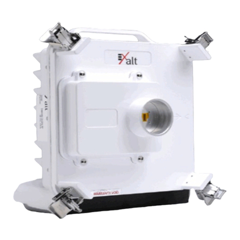
The EX-r Series GigE Exalt Digital Microwave Radios are the most advanced carrier-class point-to-
point terrestrial radio communications devices operating in the 4400 to 4900 or 5250 to 5850MHz
frequency band. The EX-r Series GigE radios are available in the following configurations:
•EX-5r GigE and EX-4.5r GigE have an integrated software selectable dual-polarization antenna
•EX-5r-c GigE and EX-4.5r-c GigE external antenna connectors, which allow connection of a dual-
polarized antenna (with software selectable polarization)
The EX-r Series GigE radios connect voice and/or digital data from one location to another, obviating
the need for copper or fiber connectivity, or enhancing existing connectivity by providing a
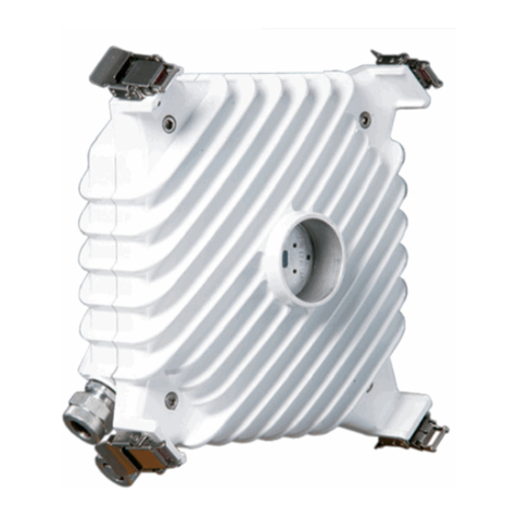
redundancy solution, a primary solution, and/or additional capacity. Figure 1 shows the Exalt EX-5r
GigE digital microwave radio.
Customer Care Hotline (USA): (408) 740-3622
Toll-Free Customer Care Hotline (USA): (844) EXALT-01 (392-5801)
Website: www.exaltcom.com
Sales e-mail: sales@exaltcom.com
Mailing Address: Exalt Wireless, Inc.
530 Division Street
Campbell, CA 95008
USA

Exalt Installation and Management Guide
EX-r Series GigE Digital Microwave Radios
2201872-004
2016-05-26
Figure 1 Exalt EX-5r GigE (integrated antenna model)
The EX-r Series GigE radios require a clear line-of-sight and proper path clearance to achieve a high-
performance, reliable connection. Perform professional path engineering and site planning before
installing this equipment.
The primary focus of this document is the installation and maintenance of the digital microwave radio,
and assumes that path engineering and site planning has already been performed.
The EX-5r GigE, and EX-5r-c GigE radios utilize radio frequencies in the 5250 to 5850 MHz range. In
most countries these frequency bands are considered as ‘license-exempt’ or ‘unlicensed.’ This means
that virtually any user may use these frequencies freely, without paying for access, or any type of pre-
notification, post-notification or registration. As a result of this designation, users may also move or
change these systems at any time, with significant flexibility to the location, orientation and
configuration of the system. However, due also to this designation, there may be uncontrolled
interference from other similar devices that occupy this spectrum. In these cases, it is up to engineering
and maintenance personnel to design the system with existing and future interference sources in mind,
recognizing that there is a chance that the interference conditions could be very dynamic, and outages
may occur on the system as a result, and that, in some very rare cases, the system may cause
interference into another system and may be required to be disengaged or modified/re-oriented to
eliminate the interference.
If the spectrum in your country is designated as ‘license-exempt’ or similar, this does not infer that the
installer may configure the system in any manner at any location. In most cases, there are regulations,
or device-based conditions that limit the use of the device, such as maximum gain antenna, antenna
types and maximum output power, as well as, in some cases, application limits, limited geography of
use, and other unique regulations. The link design engineer and/or professional installer must
determine these limitations and engineer/install the system within the confines of all local
regulations. Also, it is required to examine any regulations that may apply to peripheral equipment,
installation and cabling of the system that may be regulated for human safety, electrical code, air-
traffic control, and other safety-related categories.
In certain countries, the spectrum for this product is NOT considered to be license-exempt. In these
cases, there may be additional regulatory requirements concerning the location, frequency, power,
orientation, configuration, and other aspects of the system, including, in some cases, a need for link
registration, coordination, and fees that may apply to the system usage. Please consult your local
regulatory organization(s) to determine usage requirements.

Exalt Installation and Management Guide
EX-r Series GigE Digital Microwave Radios
201872-004 3
2016-05-26
The EX-4.5r GigE and EX-4.5r-c GigE operate in the 4400 to 4900 MHz band, which is generally
reserved for Government operators, such as NATO. In most cases, this band is considered licensed and
restricted to certain users.
In almost all cases, either for license-exempt or other designation, the product itself must be authorized
for use in your country. Either Exalt or Exalt’s agent must have applied for certification or
authorization to allow the sale and deployment of the system within the country. It is also possible that
only certain versions or configurations of the device are allowed within a particular country. Please
contact Exalt or your authorized Exalt representative for information pertaining to your country.
Basic Features
The EX-r Series GigE Digital Microwave Radios are intended for all-outdoor mounting and come with
an indoor-mounted power injector. In some cases, the radio can be mounted indoors or in an enclosure.
Depending on the configuration purchased, the associated antenna is either integrated as part of the
unit or connected separately.
For the integrated antenna model, the entire unit is typically mounted on a tower or rooftop mast
structure, with Ethernet/Power and other optional interface cables running from the unit location,
through a structure penetration, and to the power injector and connected communications equipment.
For the external antenna model, the unit is typically mounted very close to the external antenna to
minimize RF cabling and associated losses. Alternatively, the unit can be mounted at an easily
accessible location with longer RF cabling to the antenna. Proper lightning or surge suppression
devices and associated grounding are required for all connections.
Note: It is the (professional) installer’s responsibility to ensure that the radio
system is implemented in a legal fashion. Exalt is not liable for any unsafe or
illegal installations.

Exalt Installation and Management Guide
EX-r Series GigE Digital Microwave Radios
4201872-004
2016-05-26
Figure 2 Cabling—integrated antenna model
Figure 3 Cabling—external antenna model
For highest performance and reliability, it is advised to minimize the length of RF cable and associated
transmission system losses between the antenna and the radio’s antenna port.

Exalt Installation and Management Guide
EX-r Series GigE Digital Microwave Radios
201872-004 5
2016-05-26
The EX-r Series GigE radios provide connections for a combination of the following data
communication interfaces:
•10/100/1000BaseT Ethernet
•4xT1/E1 interfaces for synchronous voice traffic
The EX-r Series GigE radios are powered by a combined Power/Ethernet cable, and associated power
injector. The power injector provides 48VDC to the unit.
The EX-r Series GigE radios provide the following primary features and benefits:
•Low-latency optimization and control for voice and data connections
•Very high throughput and flexible interface configurations with voice+data combinations
•Encryption for extreme wireless security
•Easy-to-use management and configuration
•Flexible utilized channel bandwidth selection for interference avoidance and frequency
coordination
•Flexible center frequency tuning for interference avoidance and frequency coordination
•Flexible capacity to meet current connection requirements and future growth needs
•Carrier-class reliability and performance
•Connector covers (for covering and securing unused connectors)

Exalt Installation and Management Guide
EX-r Series GigE Digital Microwave Radios
201872-003 6
2015-10-23
Pre-installation Tasks
This section describes the steps necessary to prepare a site for the installation of the Exalt Digital
Microwave Radio.
Link Engineering and Site Planning
Design all terrestrial wireless links prior to purchase and installation. Generally, professional wireless
engineering personnel are engaged to determine the viability and requirements for a well-engineered
link to meet the users’ needs for performance and reliability.
The reader is referred to the Exalt document, Guidance for Engineering and Site Planning of
Terrestrial Wireless Links and the ExaltCalc path calculator. This document and calculator aid in the
pre-planning and engineering required to determine following attributes:
•Antenna type gain at each end of the link
•Antenna mounting height/location for proper path clearance
•Antenna polarization orientation
•RF cabling type, length, connectors, route, and mounting
•Antenna system grounding
•Lightning arrestor type(s), location(s), and grounding
•Radio mounting location and mechanisms
•Radio grounding
•Radio transmitter output power setting
•Anticipated received signal level (RSL) at each end
•Anticipated fade margin and availability performance at each end
•Radio settings for TDD frame length and occupied bandwidth
•Anticipated throughput performance (TDM circuit support and Ethernet)
•Anticipated system latency
With respect to radio path and site planning, these radios are generally identical to other microwave
terrestrial wireless systems. Engineering of these systems requires specific knowledge about the
radios, including:
•RF specifications (transmitter output power, receiver threshold, occupied channel bandwidth, and
carrier-to-interference)
•Regulatory limitations on transmitter output power setting and antenna type/gain
•Noise/interference profile for the intended location
Familiarization w ith the EX-r Series GigE Radios
The EX-r Series GigE radios utilize time division duplex (TDD) radio transmission. This means that
the transmitted signal in both directions uses the same center frequency and transmits in one direction
for a period of time, and then in the opposite direction for another period of time. This total period of
time is referred to as the frame length or TDD frame length, and is further discussed in Time Division
Duplex (TDD) Factors.

Exalt Installation and Management Guide
EX-r Series GigE Digital Microwave Radios
7201872-003
2015-10-23
The two radio terminals are identical hardware, except for the TDD setting in software. When the
radios are in their default state, both radios are configured as Radio B. One end of the link must be
configured as Radio A before the two ends of the radio system can communicate.
It can be considered that Radio A is the primary radio in the link. Radio A provides the master clock
and control to Radio B. For most applications, it is not important how the radio link is oriented, only
that one end is configured for Radio A and the other for Radio B. For some applications (such as,
multi-radio hub sites or repeaters), the orientation of the radio systems may be more critical. See Link
Orientation and Synchronization for details.
There are two ways to configure the radios for Radio A/B determination:
•Use the Exalt browser-based graphical user interface (GUI) – preferred.
•Connect to the radio using Telnet.
Exalt recommends using the Exalt GUI for radio configuration. This interface requires a computer
with an Ethernet port and web browser software, such as Microsoft Internet Explorer 5.0 or above. See
Configuration and Management for details on how to connect to and use the browser-based GUI
interface.
Shipping Box Contents
Unless purchased as a spare terminal, the radios are shipped as a complete hop (that is, a radio link pair
consisting of two terminals). An outer box has labeling that indicates the contents of the box, with the
part number and serial number details for both radio terminals.
Inside the outer box are two identical boxes, each of these boxes is also marked with the part number
and serial number of the individual terminal contained inside the box. The terminal box contains the
following items:
•Radio terminal (configured as Radio B)
•AC adapter
•Power injector
•Mounting kit (for pole or wall mounting)
•Accessory kit
– Grounding screw/washers
– Weather-sealing tape (required for RF connectors on the EX-5r-c GigE)
– RF connector cover (for the EX-4.5r-c GigE or EX-5r-c GigE covering the unused RF
connector, where applicable)
– RSL adapter cable
•Registration card
•Quick-start guide
Inspect the outer packaging and the contents of the boxes upon receipt. If you suspect any shipping
damage or issues with the contents, contact Exalt Customer Care.
Note: Register your system as soon as possible. A 2-year Warranty period applies to
products registered within 90 days of purchase. The Warranty period is reduced to 1-year for
unregistered products and products registered after the first 90 days.

Exalt Installation and Management Guide
EX-r Series GigE Digital Microwave Radios
201872-003 8
2015-10-23
The radio terminal boxes contain a single pre-terminated PoE cable intended for bench testing and to
make the short connection between the radio and the PoE lightning arrestor near the radio. If running a
longer cable from the radio to the PoE lightning protector (such as at the egress point), use pre-
terminated cables (sold separately). Pre-terminated cables are available in different lengths to meet a
variety of applications, and can also be used for the T1/E1 connections (where applicable).
I nitial Configuration and Back-to-Back Bench Test
Every Exalt digital microwave radio goes through extensive quality testing and performance
evaluation over the full operating temperature range prior to shipment. However, before installation, it
is strongly advised to perform several tests and tasks that are much more difficult to perform once the
radio link endpoints are distant from one another. A back-to-back bench test and pre-configuration will
provide confidence that the radio link is operational and properly configured prior to installation, so
that if troubleshooting is necessary, the radio hardware and configuration settings are eliminated from
the troubleshooting process. Verify the following in the back-to-back testing:
•Confirm that the radio system is generally operational
– Radios power-up with planned power and wiring solutions
– Regulatory Domain Key (RDK) entry successful
– RF link connects in both directions
– Traffic passes across the link
– Configure connected equipment and cabling
– Test Ethernet (CAT5e or CAT6) cabling, and/or T1/E1 cabling, any auxiliary connector
cabling and configure all interfaces
– Configure IP settings for configuration and management
– Configure passwords and security modes
– Become familiar with the configuration and management interfaces through the Exalt GUI
interface
– Configure radio parameters
– Set transmitter output power to engineered or allowed level (see RF Output Power Setting)
– Set operating center frequency
– Set link distance, occupied channel bandwidth, and frame length
•Make detailed radio performance measurements
Note: Exalt radios with the RDK function are DISABLED when initially shipped. To
ENABLE the radio, a valid RDK must be entered on the Administration Settings Page page of
the Exalt GUI. The RDK references the unit's serial number and is provided based on the
country and/or region where the radio system will be deployed. The RDK is obtained through
your Exalt Authorized distributor or reseller.
Note: Some countries require Dynamic Frequency Selection (DFS), which delays the
transmitter turn-on time during the initial Channel Availability Check period of 1 minute. In
accordance with these regulations, the radios boot up, and then wait for 1 minute before
linking.

Exalt Installation and Management Guide
EX-r Series GigE Digital Microwave Radios
9201872-003
2015-10-23
– Measure transmitter output power
– Measure receiver threshold performance
– Confirm unfaded error-free performance
Some of these tasks may not be possible or practical within a bench test environment due to the nature
of the remote connectivity of peripheral equipment. However, it is good practice to perform as much as
possible in this environment to minimize field/installation time and troubleshooting efforts.
Detailed performance measurements are usually not required for pre-installation, but can be easily
performed at this stage and may be helpful for later troubleshooting efforts or for internal records.
During troubleshooting, there may often be a point at which a back-to-back bench test should be
performed to verify many or all of the above items, and in the case of a suspected faulty device, to help
confirm the fault and determine which end of the system is at fault and in need of repair or
replacement.
RF Output Power Setting
The maximum RF output power is bounded by one of the following criteria:
•Maximum RF output power setting capability of the radio device
•Maximum RF output power allowed/authorized by the local government regulations and for this
specific device
•Maximum effective isotropic radiated power (EIRP) of the transmission system allowed/
authorized by the local government regulations and for this specific device
•Desired RSL to not exceed the maximum RSL allowed by the device
•Desired RSL to minimize/eliminate interference into neighboring systems
Time Division Duplex (TDD) Factors
The EX-r Series GigE radios are very dynamic, allowing the installer to optimize and control the
performance of the radio system for the intended application. The following parameters must be
carefully determined during the link engineering phase:
•Link distance
•Bandwidth
•TDD frame size
•Mode (modulation)
The setting of the above parameters determines the following performance factors:
•Number of supported T1/E1 channels
•Ethernet throughput
Note: See Back-to-back Bench Testing for detailed instructions.
Note: In many cases the radio must be pre-configured for legal maximum output power
before connecting to the antenna and transmission system. Instructions for adjusting the
output power can also be found at the rear of this guide in the EIRP section for your region.

Exalt Installation and Management Guide
EX-r Series GigE Digital Microwave Radios
201872-003 10
2015-10-23
•System latency (delay)
Use the ExaltCalc calculator to determine optimum settings for the above parameters to meet the needs
of your application.
The following generalizations can be made with regards to these factors:
•The shorter the TDD frame size, the lower the latency
•The shorter the link distance, the lower the latency, the higher the throughput
•The longer the TDD frame size, the higher the throughput
•The higher the bandwidth, the higher the capacity
•The higher the mode, the higher the capacity
Link Orientation and Synchronization
Link orientation refers to the Radio A and Radio B placement in your network. Link synchronization
refers to using external or internal timing to coordinate multiple links.
For every link, one end of the radio link must be configured as Radio A, while the other end is
configured as Radio B. In single-link systems, it does not matter which end of the system is mounted at
which end of the link, and there is typically no requirement for any link synchronization.
Link orientation and synchronization are more important for networks with site(s) where there is more
than one link of the same type or for sites using the same type of radio that are very close to each
another at one or both ends.
Configure collocated radio terminals for the same link orientation. That is, configure all radios at the
same location as Radio A or Radio B.
Use link synchronization for collocated links. The radios allow the use of an internal synchronization
source or an optional GPS synchronization kit. This synchronization controls the transmitter and
receiver frame timing so that collocated radios are transmitting at the same time and receiving at the
same time. This can substantially reduce the opportunity for self-interference. Without
synchronization, collocated radios may be transmitting and receiving at the same time, incurring near-
end interference.
Note: Disable all T1/E1 ports if there are no T1/E1 interfaces connected. This shifts all available
throughput to the Ethernet interface.
Note: If a selected combination of the Link Distance, Frame Size, Bandwidth, and Mode
parameters cannot support all the desired T1 or E1 ports, the ports that cannot be supported are
automatically disabled. Priority is placed on the T1/E1 port number. That is, the first port to be
disabled, if necessary, is the highest port number, such as Port 4. See T1/E1 Configuration Pages
for more information.

Exalt Installation and Management Guide
EX-r Series GigE Digital Microwave Radios
11 201872-003
2015-10-23
Radio A/ B Configuration
Use the Exalt GUI to configure the radio terminals for Radio A and Radio B orientation. Since many
other parameters also need to be set, and the Exalt GUI is needed for these configurations, this is the
best way to completely configure the radio terminals.
Radios arrive from manufacture in default configuration, orientated as Radio B and configured as
shown in Table 1.
Note: It is not always necessary to synchronize collocated radios. If antennas are substantially
separated or blocked from one another and/or frequency separation tuning is used, the
opportunity for near-end interference can be eliminated.
Note: When GPS synchronization is required or desired, one GPS kit is required for each EX-
r Series GigE radio link in the connected or collocated network.
Table 1 Factory default settings
Parameter Setting
Transmit Power +4dBm
Link Distance <10 miles
Bandwidth 8 MHz (10 MHz for some regulatory domains)
Mode Mode 1
TDD Frame Size 2ms
Link Security Key 000000000000
Administration Password password
User Password password
IP Address 10.0.0.1
IP Mask 255.0.0.0
IP Gateway 0.0.0.0
Ethernet Interface Alarm Enabled, Auto-negotiate
T1/E1 Enabling All Disabled
Note: In many cases, the system design will not be identical to the factory default
configuration, and in some cases, these differences prohibit the installation of the radio. If at
all possible, obtain a computer and configure the radio terminals using the browser-based
GUI. See Exalt Graphical User Interface (GUI) for details.

Exalt Installation and Management Guide
EX-r Series GigE Digital Microwave Radios
201872-003 12
2015-10-23
Radio Reset
Use the reset function if the IP address and/or passwords are lost. Use the following steps to perform a
critical parameter reset:
1Remove power from the radio by disconnecting the AC adapter from the power injector.
2Hold down the RESET button on the power injector while applying power.
Hold the RESET button down through the entire power cycle and monitor the DATA+POWER
left LED on the power injector. Release the RESET button only after the LED is in the steady state
(approximately 2 minutes).
3Release the RESET button.
The following configurations are reset on the radio:
•IP address = 10.0.0.1
•IP mask = 255.0.0.0
•IP gateway = 0.0.0.0
•Administration password = password
•User password = password
Radio Synchronization
The radio synchronization feature improves the performance of Exalt radios operating in the same
frequency band and that are collocated (such as in repeater and hub configurations). Radio
synchronization ties radio systems together to operate off of a common clock system, ensuring that all
radios simultaneously transmit and receive, and thus eliminating near-field interference issues and
related radio system coupling.
Synchronization Modes
Synchronization can be accomplished using either an internal or external source. In either case, one
radio in the network must be defined as the primary sync source (A) radio.
A Global Positioning System (GPS) kit from Exalt is required to implement external source
synchronization. GPS synchronization is not available on all radio models. Contact your Exalt
representative for details.
Synchronization implementation only requires one synchronization source for any interconnected
network. The system also implements a redundancy configuration to maintain a majority of the
synchronization functions in case of primary radio failure.
For internal synchronization, the primary radio is designated SYNC SOURCE. This radio provides the
master timing for all interconnected radios. SYNC SOURCE radios and collocated radios must be
configured as Radio A.
Collocated radios must be in SYNC RECIPIENT mode; they receive sync signaling from the SYNC
SOURCE, either directly or daisy-chained with other collocated radios. Alternatively, the radio(s) can
be placed in AUTO SYNC mode. AUTO SYNC synchronizes the radios to any source provided on the
SYNC IN port. However, if an appropriate synchronization signal is unavailable, the radio becomes
the SYNC SOURCE for all connected radios.
This manual suits for next models
3
Table of contents
Other Exalt Radio manuals

Exalt
Exalt EX-5r GigE Instruction Manual
Exalt
Exalt ExtendAir series Programming manual
Exalt
Exalt EX-5i-DS3-GigE Programming manual
Exalt
Exalt S Series Programming manual

Exalt
Exalt ExtendAir G2 Programming manual
Exalt
Exalt ExtendAir eMIMO r5050 Series User manual

Exalt
Exalt ExtendAir series User manual

Exalt
Exalt ExtendAir r4900 Programming manual

Exalt
Exalt EX-2.4i Lite Programming manual

Exalt
Exalt EX-5i Lite Instruction Manual

