Exalt r Series Manual

r-Series
Digital Microwave Radios
Installation and Management
Manual
Includes Models:
EX-4.9r, EX-4.9r-c, EX-4.9r-x, EX-4.9r-xc
EX-5r, EX-5r-c, EX-5r-x, EX-5r-xc
Part Number: 50000007 (ETSI)
Date: 2007-02-12

Exalt Communications Inc.
r-series Installation and Management Manual
5000007 (ETS) ii
2007-02-12 (draft)
Legal Notice
The information contained herein is the property of Exalt Communications, Inc. (“Exalt”) and is
supplied without liability for errors or omissions. No part of this document may be reproduced,
in any form, except as authorized by contract or other written permission from the owner.
Any brand names and product names included in this manual are trademarks, registered
trademarks, or trade names of their respective holders.
The contents of this document are current as of the date of publication. Exalt reserves the right to
change the contents without prior notice.
The publication of information in this document does not imply freedom from patent or other
rights of Exalt or others.
© 2007 Exalt Communications Inc. All rights reserved.
The Exalt logo is a trademark of Exalt Communications, Inc.
Open-Source License Information
In addition to proprietary software/firmware, which is the sole intellectual property of Exalt, the
EX-5r Digital Microwave Radios make use of public (open-source) software/firmware within the
terms of use of their respective shared license agreements. Exalt will supply copies of any of this
code, within the terms of their individual licensing agreements, upon request.
Open-Source Code License Agreement Website
Linux Operating System GNU GPL Version 2 www.gnu.org
BusyBox CLI GNU GPL Version 2 www.gnu.org;
www.busybox.net
GoAhead Web Server Copyright (c) 2003 GoAhead Software, Inc.
All Rights Reserved. www.goahead.com
U-boot Boot Code GNU GPL Version 2 www.gnu.org
www.sourceforge.net
Net-SNMP (see Copyright Notices on page 89) www.sourceforge.net

Exalt Communications Inc.
r-series Installation and Management Manual
5000007 (ETS) iii
2007-02-12 (draft)
About this Document
This manual provides a complete description of the EX-5r family of Digital Microwave Radios
and related software. This manual provides planners, engineers, installers, system administrators,
and technicians general and specific information related to the planning, installation, operation,
management, and maintenance of these devices.
Revision History
Date Detail
2006-09-18 EX-5r release 1.0.0
2006-12-20 Draft for ETSI/CE
2007-02-12 Draft for 4.9r series
Icons
The following icons denote specific types of information.
(Warning) Denotes information pertaining to potential danger to human life.
(Caution) Denotes information pertaining to potential danger to property.
(Note) Denotes useful or unique information.
CAUTION
!

Exalt Communications Inc.
r-series Installation and Management Manual
5000007 (ETS) iv
2007-02-12 (draft)
General Compliance and Safety
The usage of radio transmission devices is subject to specific regulatory requirements governed
by regional legislation. In most cases, the specific device must be authorized for use in a given
country and must be installed and adjusted in accordance with specific radio-frequency settings
and in a manner that has been authorized specific to the device itself in accordance with the
specific location of the device. Some users may be completely or partially restricted from use of
the device. Please consult local governmental agency/agencies for regulatory requirements
before use, or contact Exalt or your Exalt authorized dealer for assistance.
Do not modify this device in any way without the express written consent of Exalt. Modification
voids the manufacturer warranty, and may also be illegal in accordance to government
regulations. In addition, there are no user-serviceable parts or assemblies inside the product
housing. There may also be voltages, signals, and mechanisms within the device that could be
harmful to human safety.
The mounting of this device and associated peripherals and connections (inclusive of antenna
mast, antenna, cabling, egress, lightning protection devices, grounding, power, and so on) may
be subject to regional requirements for health and human safety. A qualified professional
installer and an electrician are highly recommended, and may be required by law.
Exalt cannot warranty the device or be found liable for any unauthorized use or installation of the
device.
Regulatory Notices
Federal Communications Commission (FCC), United States
The device is allowed to be used provided it does not cause interference to other devices. It is not
guaranteed to provide protection against interference from other electronic and radio devices.
The system has been tested and found to comply with the limits of a class B digital device,
pursuant to Part 15 of the FCC Rules. These limits are designed to provide reasonable protection
against harmful interference in a residential installation. This equipment generates uses and can
radiate radio frequency energy and, if not installed and used in accordance with the instructions,
may cause harmful interference to radio communications. However, there is no guarantee that
interference will not occur in a particular installation. If this equipment does cause harmful
interference to radio or television reception, which can be determined by turning the equipment
off and on, the user is encouraged to try to correct the interference by one of more of the
following measures:
•Reorient or relocate the receiving antenna.
•Increase the separation between the equipment and receiver.
•Connect the equipment into an outlet on a circuit different from that to which the receiver is
connected.
•Consult the dealer or an experienced radio/TV technician for help.

Exalt Communications Inc.
r-series Installation and Management Manual
5000007 (ETS) v
2007-02-12 (draft)
Shielded cables and I/O cords must be used for this equipment to comply with the relevant FCC
regulations.
Changes or modifications not expressly approved in writing by Exalt may void the user’s
authority to operate this equipment.
This device must be professionally installed.
To comply with regulations, the output power of this device may need to be adjusted in
accordance to the associated transmission system. See RF Output Power Setting on page 10 for
details.
The antenna associated with this device shall be mounted in a location that is at least 10'/3m
away from humans that may be subject to long-term or continuous exposure.
Industry Canada (IC), Canada
This Class B Digital apparatus meets all the requirements of the Canadian Interference-Causing
Equipment Regulations.
Cet appareil numerique de la classe B respecte les exigences du Reglement sur le material broilleur du
Canada.
This device complies with RSS-210 of Industry Canada. Operation is subject to the following
two conditions:
1. this device may not cause interference, and
2. this device must accept any interference, including interference that may cause undesired
operation of the device.
Antennas Supported in Canada
The device is designed to operate with the antennas listed in Table 1, which have a maximum
gain of 37.5dBi. Antennas not included in the list or having a gain greater than 37.5dBi are
strictly prohibited for use with this device. The required antenna impedance is 50 Ohms.
Table 1 Supported antennas—Canada
Manufacturer Model # Description Gain dBi
(
mid-band
)
Andrew
P2F
-
52
-
N
2
-
foot Dish
29.4
Andrew
PX2F
-
52
-
N
2
-
foot Xpol Dish
29.4
Andrew
P3F
-
52
-
N
3
-
foot Dish
33.4
Andrew
PX3F
-
52
-
N
3
-
foot Xpol Dish
33.4
Andrew
P4F
-
52
-
N
4
-
foot Dish
34.9
Andrew
PX4F
-
52
-
N
4
-
foot Xpol Dish
34.9
Andrew
HP2F
-
52
-
NPA
2
-
foot HP Dish
29.0
Andrew
HPX2F
-
52
-
NPA
2
-
foot Xpol HP Dish
29.0
Andrew
HP3F
-
52
-
NPA
3
-
foot HP Dish
33.0
Andrew
HPX3F
-
52
-
NPA
3
-
foot Xpol HP Dish
33.0
A
ndrew
HP4F
-
52
-
NPA
4
-
foot HP Dish
34.5

Exalt Communications Inc.
r-series Installation and Management Manual
5000007 (ETS) vi
2007-02-12 (draft)
Andrew
HPX4F
-
52
-
NPA
4
-
foot Xpol HP Dish
34.5
Andrew
HP6F
-
52
-
NPA
6
-
foot HP Dish
37.2
Andrew
HPX6F
-
52
-
NPA
6
-
foot Xpol HP Dish
37.2
Andrew
FPA5250D06
-
N
6
-
inch Panel
18.0
Andrew
FPA5250D12
-
N
1
-
foot Panel
23.6
Exalt (Integral) 1-foot Xpol Panel 20.0
Gabriel
DFPS.5
-
52
6
-
inch Panel
18.0
Gabriel
DFPD1
-
52
1
-
foot Panel
23.5
Gabriel
DFPD2
-
52
2
-
foot Panel
28.0
Gabriel
QF2
-
52
-
N
2
-
foot Dish
28.5
Gabriel
QF2.5
-
52
-
N
2.5
-
foot Dish
31.2
Gabriel
QF4
-
52
-
N
4
-
foot Dis
h
34.8
Gabriel
QFD2
-
52
2
-
foot Xpol Dish
28.4
Gabriel
QFD2.5
-
52
2.5
-
foot Xpol Dish
31.1
Gabriel
QFD4
-
52
4
-
foot Xpol Dish
34.7
Gabriel
HQF2
-
52
-
N
2
-
foot HP Dish
28.2
Gabriel
HQF4
-
52
-
N
4
-
foot HP Dish
34.4
Gabriel
HQF6
-
52
-
N
6
-
foot HP Dish
37.4
Gab
riel
HQFD2
-
52
2
-
foot Xpol HP Dish
28.1
Gabriel
HQFD2.5
-
52
2.5
-
foot Xpol HP Dish
30.7
Gabriel
HQFD4
-
52
4
-
foot Xpol HP Dish
34.3
Gabriel
HQFD6
-
52
6
-
foot Xpol HP Dish
37.3
MTI
MT
-
485001
7.5
-
inch Panel
19.0
MTI
MT
-
485002
1
-
foot Panel
23.0
MTI
MT
-
48
6004
18
-
inch Panel
26.0
MTI
MT
-
486001
2
-
foot Panel
28.0
MTI
MT
-
485005
7.5
-
inch Xpol Panel
18.0
MTI
MT
-
485025
15
-
inch Xpol Panel
23.0
Proxim
5054
-
WA
-
15
-
STN
Window Panel
15.0
Radio Waves
FP.5
-
5
-
18
6
-
inch Panel
18.0
Radio Waves
FP1
-
5
-
24
1
-
foot Pan
el
23.8
Radio Waves
FP2
-
5
-
28
2
-
foot Panel
28.0
Radio Waves
FPD.5
-
5
-
18
6
-
inch Xpol Panel
18.0
Radio Waves
SP1
-
5.2
1
-
foot Dish
22.5
Radio Waves
SP2
-
5.2
2
-
foot Dish
29.0
Radio Waves
HP2
-
5.2
2
-
foot HP Dish
28.6
Radio Waves
SP3
-
5.2
3
-
foot Dish
32.0
Radio Waves
SP4
-
5.2
4
-
foot Dish
34.8
Radio Waves
SPD2
-
5.2
2
-
foot Xpol Dish
28.1
Radio Waves
SPD3
-
5.2
3
-
foot Xpol Dish
31.1
Radio Waves
SPD4
-
5.2
4
-
foot Xpol Dish
34.4
Radio Waves
SPD6
-
5.2
6
-
foot Xpol Dish
37.5
RFS
SPF2
-
52A
2
-
foot Dish
27.9
RFS
SPF3
-
52A
3
-
foot Dish
31.4
RFS
SPF4
-
52A
4
-
foot Dish
33.9
RFS
SPF6
-
52A
6
-
foot Dish
37.4
RFS
SDF4
-
52A
4
-
foot HP Dish
33.9

Exalt Communications Inc.
r-series Installation and Management Manual
5000007 (ETS) vii
2007-02-12 (draft)
The antenna associated with this device shall be mounted in a location that is at least 10'/3m
away from humans that may be subject to long-term or continuous exposure.
Europe/ITU (ETSI and CE Mark)
The EX-5r family complies with ETS 301 893 for the 5.3 and 5.47 GHz bands for license-
exempt use for most countries recognizing ETSI or ITU band assignments. These bands require
Dynamic Frequency Selection (DFS) and Transmitter Power Control (TPC) for radar-detection
and avoidance. There is a +30dBm EIRP limit applied to this band. Transmitter power must be
adjusted accordingly with respect to the RF cabling losses and antenna gains associated with
each terminal.
The EX-5r family complies with ETS 302 502 for the 5.8GHz band. This band is not yet
harmonized for all countries recognizing ETSI or ITU band assignments. Consult the individual
country regulations or your Exalt Communications representative for details. This band requires
DFS and TPC for radar-detection and avoidance. There is a +33dBm EIRP limit for use of the
10MHz BW setting (called 8MHz on GUI), and a +36dBm EIRP limit for use of the 20MHz BW
setting (called 16MHz on GUI).
All models comply with the requirements for CE Mark (EN 60950) and EMC (EN 301-489-17)
when used with the AC adapter included with each model. No substitutions shall be made, and
all wiring and grounding instructions contained in this manual must be followed to ensure safety
in accordance to the standards.
Regulatory Notices (4.9GHz Model)
The EX-4.9r is a licensed-band product operating within Part 90 of the FCC regulations and
RSS-111 of Industry Canada. These bands are specifically reserved for Public Safety
applications and related agencies, in accordance with these regulations.
Professional installation is required, and transmitter power reduction may be required, depending
on transmission system gains and losses, in accordance with instructions found in RF Output
Power Setting on page 10.
The transmitter power of the device must be reduced by 1dB for every 1dB that the antenna gain
exceeds 26dBi (inclusive of transmission system losses).
RFS
SDF6
-
52A
6
-
foot HP Dish
37.4
RFS
MA0528
-
19AN
7.5
-
inch Panel
19.0
RFS
MA0528
-
23AN
1
-
foot Panel
23.0
RFS
MA0528
-
28AN
2
-
f
oot Panel
28.0

Exalt Communications Inc.
r-series Installation and Management Manual
5000007 (ETS) viii
2007-02-12 (draft)
Safety Notices
1. Review this entire guide for important installation instructions BEFORE attempting to
install this product.
2. This product is intended to be installed, used, and maintained by experienced
telecommunications personnel only.
3. Employ a properly licensed or authorized electrician to install or evaluate/certify the
installation of all power and grounding related to the use of this equipment and all
connected devices.
4. The device(s) shall only be connected to AC power sources provided by the supplier or to
DC sources within the device specifications (FCC/IC only). Use a separate breaker circuit
at the power source.
5. Lightning, surge protection devices, and earth grounding are required for most installations
to ensure human safety. Consult a qualified electrician.
6. Servicing of this device should be performed by authorized personnel only. Do not
disassemble this device. By opening or removing any covers you may expose yourself to
hazardous energy parts. Incorrect reassembly of this product can cause a malfunction,
and/or electrical shock, when the unit is subsequently used.
7. Do not connect or disconnect the power connection to the device when the power supply is
plugged into an AC outlet. To connect, first connect the power connection to the device,
and then apply power (or plug in) at the outlet. To disconnect, disengage power at the outlet
or unplug, and then disconnect the direct connection to the device.
8. Do not insert any object of any shape or size inside this product at any time, whether
powered or not. Objects may contact hazardous energy components that could result in a
risk of fire or personal injury.
9. Liquids shall not come in contact with, or enter the inside of the device at any time.
10. Proper ventilation and/or airflow shall be provided surrounding the equipment. Items shall
not come in contact with heat-sinking materials. Ensure that ambient operational and
storage temperature specifications are maintained at all times.
11. Equipment is suitable for mounting on noncombustible surfaces only.
12. Do not move or alter the marking labels.

Exalt Communications Inc.
r-series Installation and Management Manual
5000007 (ETS) ix
2007-02-12 (draft)
Exalt Limited Hardware Warranty
Exalt Communications, Inc. (“Exalt”) warrants solely to the original purchaser (“Purchaser”) that
the EX-5r series or the EX-4.9r Series (the “Product”) will substantially conform in all material
respects to the relevant Exalt published specifications that apply at the time of manufacture of
such Product for two (2) years from the date of tender of Product by Exalt from FOB point
designated by Exalt (the “Warranty Period”). Proof-of-purchase in the form of an invoice,
payment of invoice, or delivery waybill must be supplied, if requested by Exalt, in case of any
dispute of warranty start date. Exalt shall within the Warranty Period, at its own option: (A) use
reasonable efforts to remedy any reproducible Product defect covered by this limited warranty
within a reasonable period of time; (B) replace the defective Product with a functionally
equivalent product (repair parts and products may be either reconditioned or new, but, if
reconditioned, shall be of the same quality as new parts or products); or (C) if Exalt determines
that it is unable to repair or replace such Product, Exalt will refund to Purchaser the amount
actually paid by Purchaser for the applicable Product. All replaced parts become the property of
Exalt. Exalt may, at its sole option, refuse to accept as defective Product that (i) is subject to the
exclusions set forth below; or (ii) cannot be demonstrated to be defective by Exalt and Purchaser
is unable to provide adequate information describing how the Product failed. Such Product will,
at Purchaser’s option and expense, either be: (a) returned to Purchaser in the state received, or (b)
repaired and returned to Purchaser. Repaired or replaced Product will be warranted for the
remainder of the original Warranty Period, but not less than ninety (90) days.
Registration
Purchaser is required to register its Product, within ninety (90) days of purchase, for full
warranty support. Unregistered or late-registered Product will receive a Warranty Period of only
one (1) year.
Exclusions
This limited warranty will not apply to: (A) any Product that: (i) has been modified or altered by
any party other than Exalt; (ii) has been subject to accident, misuse, abnormal wear and tear,
neglect, or mistreatment; (iii) has been damaged during installation of the Product; (iv) has been
damaged by the equipment or system with which the Product is used; (v) has sustained damage
to the Products’ interface or power connectors; (vi) are determined to be stolen; or (vii) has been
damaged caused by fire, power changes, other hazards, or acts of God (including without
limitation lightning); or (B) any software included in any such Product. The warranty applies
only to Products that can be identified by the Exalt trademark, trade name, serial number or logo
affixed to them. Exalt does not warrant any Product that is not manufactured by, for, or with
permission from Exalt. The Products covered by this warranty are not consumer products and
are not intended for personal, family, or household purposes.

Exalt Communications Inc.
r-series Installation and Management Manual
5000007 (ETS) x
2007-02-12 (draft)
RMA Procedures
A return material authorization (RMA) is required prior to returning Product to Exalt for
warranty or out-of-warranty repair/evaluation. As such, Purchaser must use the following
procedure:
1. Contact Exalt (see Introduction on page 1 for current contact data) and request an RMA
number. Please be prepared to provide the serial number of the Product, the date of
purchase, and a description of the failure that is as complete as possible.
2. Pack the Product in its original container and packing or an equivalent.
3. Write the RMA number CLEARLY on the outside of the shipping box.
4. For services during the Warranty Period, cost of shipment to Exalt’s authorized service
center, taxes, duty, tariffs, risk of loss and insurance charges to Exalt shall be borne by the
Purchaser. Cost of return shipment and insurance charges shall be borne by Exalt and will
be made by Exalt’s choice of carrier and method/schedule of shipment. Purchaser may
expedite return shipments, upon request, at its own expense.
PRODUCTS RETURNED WITHOUT A DULY ISSUED RMA NUMBER WILL BE
RETURNED TO PURCHASER AT PURCHASER’S EXPENSE.
THIS EXPRESS WARRANTY IS IN LIEU OF ALL OTHER WARRANTIES, EXPRESSED,
IMPLIED OR STATUTORY, REGARDING THE PRODUCT, AND EXALT, ITS
SUPPLIERS AND LICENSORS HEREBY EXPRESSLY DISCLAIM ALL SUCH IMPLIED
AND EXPRESS WARRANTIES, INCLUDING WITHOUT LIMITATION ANY AND ALL
IMPLIED WARRANTIES OF FITNESS FOR A PARTICULAR PURPOSE, TITLE,
INTERFERENCE WITH QUIET ENJOYMENT, NON-INFRINGEMENT OF THIRD-PARTY
RIGHTS AND MERCHANTABILITY. FURTHER, EXALT DOES NOT WARRANT
RESULTS OF USE OR THAT PURCHASER’S USE OF THE PRODUCT WILL BE
UNINTERRUPTED OR ERROR FREE. NO WARRANTIES ARE MADE BY EXALT’S
SUPPLIERS OR LICENSORS. EXCEPT FOR THE EXPRESS WARRANTY STATED
HEREIN, THE PRODUCT IS PROVIDED “AS IS” AND WITH ALL FAULTS. THE ENTIRE
RISK AS TO SATISFACTORY QUALITY, ACCURACY, AND EFFORT IS WITH
PURCHASER.
REGARDLESS OF WHETHER ANY REMEDY SET FORTH HEREIN FAILS OF ITS
ESSENTIAL PURPOSE OR OTHERWISE, AND EXCEPT FOR BODILY INJURY, IN NO
EVENT WILL EXALT, ITS SUPPLIERS OR LICENSORS BE LIABLE TO PURCHASER
OR TO ANY THIRD PARTY UNDER ANY TORT, CONTRACT, NEGLIGENCE, STRICT
LIABILITY OR OTHER LEGAL OR EQUITABLE THEORY FOR ANY LOST PROFITS,
LOST OR CORRUPTED DATA, COMPUTER FAILURE OR MALFUNCTION,
INTERRUPTION OF BUSINESS, OR OTHER SPECIAL, INDIRECT, INCIDENTAL OR
CONSEQUENTIAL DAMAGES OF ANY KIND ARISING OUT OF THE USE OR
INABILITY TO USE THE PRODUCT, EVEN IF EXALT HAS BEEN ADVISED OF THE
POSSIBILITY OF SUCH LOSS OR DAMAGES AND WHETHER OR NOT SUCH LOSS OR
DAMAGES ARE FORESEEABLE.

Exalt Communications Inc.
r-series Installation and Management Manual
5000007 (ETS) xi
2007-02-12 (draft)
IN NO EVENT SHALL EXALT’S AND ITS SUPPLIERS’ AGGREGATE LIABILITY
EXCEED AN AMOUNT EQUAL TO THE PURCHASE PRICE OF THE PRODUCT PAID
BY PURCHASER THAT IS THE SUBJECT OF A CLAIM. ANY CLAIM ARISING OUT OF
OR RELATING TO THIS AGREEMENT MUST BE BROUGHT WITHIN ONE (1) YEAR
AFTER THE OCCURRENCE OF THE EVENT GIVING RISE TO SUCH CLAIM. IN
ADDITION, EXALT DISCLAIMS ALL LIABILITY OF ANY KIND OF EXALT’S
SUPPLIERS.

Exalt Communications Inc.
r-series Installation and Management Manual
5000007 (ETS) xii
2007-02-12 (draft)
Table of Contents
Legal Notice....................................................................................................................................ii
Open-Source License Information..................................................................................................ii
About this Document.....................................................................................................................iii
Revision History ........................................................................................................................iii
Icons...........................................................................................................................................iii
General Compliance and Safety.....................................................................................................iv
Regulatory Notices.........................................................................................................................iv
Federal Communications Commission (FCC), United States ................................................... iv
Industry Canada (IC), Canada..................................................................................................... v
Antennas Supported in Canada............................................................................................... v
Europe/ITU (ETSI and CE Mark).............................................................................................vii
Regulatory Notices (4.9GHz Model)............................................................................................vii
Safety Notices..............................................................................................................................viii
Exalt Limited Hardware Warranty.................................................................................................ix
Registration................................................................................................................................ ix
Exclusions..................................................................................................................................ix
RMA Procedures......................................................................................................................... x
List of Figures..............................................................................................................................xvi
List of Tables ..............................................................................................................................xvii
Introduction..................................................................................................................................... 1
Related Documentation and Software ........................................................................................ 1
The Exalt r-Series Digital Microwave Radios............................................................................ 1
Basic Features............................................................................................................................. 3
Pre-installation Tasks...................................................................................................................... 6
Link Engineering and Site Planning........................................................................................... 6
Familiarization with the r-Series................................................................................................. 7
ETSI Compliance – EIRP limits............................................................................................. 7
Shipping Box Contents...........................................................................................................8
Back-to-Back Bench Test and Configuration............................................................................. 9
RF Output Power Setting.......................................................................................................... 10

Exalt Communications Inc.
r-series Installation and Management Manual
5000007 (ETS) xiii
2007-02-12 (draft)
United States Compliance..................................................................................................... 10
EX-4.9r FCC (USA) EIRP.................................................................................................... 11
FCC (USA) EIRP.................................................................................................................. 11
Canada Compliance.............................................................................................................. 12
IC (Canada) EIRP................................................................................................................. 12
EX-4.9r Series IC (Canada) EIRP ........................................................................................ 12
EX-5r Series IC (Canada) EIRP ........................................................................................... 12
ETSI Compliance – EIRP limits........................................................................................... 13
Time Division Duplex (TDD) Factors...................................................................................... 14
Link Orientation and Synchronization...................................................................................... 15
Radio A/B Configuration...................................................................................................... 15
System Installation and Initiation Process.................................................................................... 17
Record Keeping ........................................................................................................................ 19
Installation..................................................................................................................................... 20
Mechanical Configuration and Mounting................................................................................. 20
Mounting the System............................................................................................................ 20
Radio Ports and Indicators........................................................................................................ 22
Connector Overview............................................................................................................. 22
LED Indicators...................................................................................................................... 23
RESET Button ...................................................................................................................... 24
Power ........................................................................................................................................ 24
Terminating the RF Connectors r-(x)c Series models only)................................................. 25
AC Power.............................................................................................................................. 25
Power Injector....................................................................................................................... 26
Reset to Critical Factory Settings ......................................................................................... 27
Antenna/Transmission System.................................................................................................. 27
Initial Antenna Mounting r-(x)c Series models only)........................................................... 29
Transmission Line from Antenna to Radio r-(x)c Series models only................................. 30
RF Lightning Arrestor........................................................................................................... 32
Antenna Alignment................................................................................................................... 32
Configuration and Management ................................................................................................... 34
Telnet into the Command Line Interface (CLI)........................................................................ 34

Exalt Communications Inc.
r-series Installation and Management Manual
5000007 (ETS) xiv
2007-02-12 (draft)
Connect to the Radio in a Telnet Session ............................................................................. 34
Telnet ........................................................................................................................................ 34
Exalt Graphical User Interface (GUI)....................................................................................... 35
Preparing to Connect............................................................................................................. 35
Make Connections ................................................................................................................ 36
Log In.................................................................................................................................... 36
Login Privileges.................................................................................................................... 37
Quick-Start................................................................................................................................ 38
Navigating the GUI................................................................................................................... 39
Summary Status Section....................................................................................................... 39
Navigation Panel................................................................................................................... 40
Radio Information Page............................................................................................................ 41
Administration Settings Page.................................................................................................... 42
System Configuration Page....................................................................................................... 44
ETSI Compliance – EIRP limits........................................................................................... 47
Ethernet Interface Configuration Page...................................................................................... 49
T1/E1 Configuration Pages....................................................................................................... 50
T1 Interface Configuration Page........................................................................................... 51
E1 Interface Configuration Page........................................................................................... 52
T1/E1 Loopback.................................................................................................................... 52
File Transfer Page..................................................................................................................... 54
File Activation Page.................................................................................................................. 57
Simple Network Management Protocol (SNMP) Configuration.............................................. 58
Alarms Page.............................................................................................................................. 59
Performance Page ..................................................................................................................... 61
Event Log Page......................................................................................................................... 64
Diagnostic Charts Page............................................................................................................. 65
Spectrum Analyzer Page........................................................................................................... 66
Reboot Page.............................................................................................................................. 67
Manual Page.............................................................................................................................. 68
Troubleshooting............................................................................................................................ 69
General Practices ...................................................................................................................... 69

Exalt Communications Inc.
r-series Installation and Management Manual
5000007 (ETS) xv
2007-02-12 (draft)
Typical Indications of Issues .................................................................................................... 70
Improper RF Cable Termination............................................................................................... 71
Multipath Propagation .............................................................................................................. 72
RF Interference ......................................................................................................................... 72
Path Obstruction........................................................................................................................ 73
Misaligned Antenna.................................................................................................................. 73
Faulty Antenna.......................................................................................................................... 73
Improper Grounding ................................................................................................................. 73
Insufficient Link Margin........................................................................................................... 74
Moisture in the Transmission System....................................................................................... 74
Specifications................................................................................................................................ 75
Physical Specifications ............................................................................................................. 75
Common System Specifications............................................................................................... 75
EX-4.9r System Specifications................................................................................................. 76
System Specifications, 5.3GHz Band....................................................................................... 77
System Specifications, 5.4GHz Band....................................................................................... 78
System Specifications, 5.8GHz Band....................................................................................... 79
Interfaces................................................................................................................................... 80
Back-to-back Bench Testing......................................................................................................... 82
Basic Test.................................................................................................................................. 82
Connections EX-5r-c only .................................................................................................... 82
EX-5r Basic Test Configuration ........................................................................................... 83
Verify Connection................................................................................................................. 83
Specification Performance Verification—EX-5r-(x)c only...................................................... 83
Interface Connections ................................................................................................................... 86
T1/E1 Connections.................................................................................................................... 86
RSL & GPS Sync Connector.................................................................................................... 87
Power/Ethernet Connector........................................................................................................ 87
Copyright Notices......................................................................................................................... 89
Net-SNMP................................................................................................................................. 89
Index ............................................................................................................................................. 94

Exalt Communications Inc.
r-series Installation and Management Manual
5000007 (ETS) xvi
2007-02-12 (draft)
List of Figures
Figure 1 Exalt EX-5r (integrated antenna model)..................................................................... 2
Figure 2 Mounting and cabling—integrated antenna model..................................................... 4
Figure 3 Cabling and mounting—external antenna model ....................................................... 4
Figure 4 Radio installation tasks............................................................................................. 18
Figure 5 Pole-mount example ................................................................................................. 20
Figure 6 EX-5r pole and wall mount (with azimuth and elevation adjustment)..................... 21
Figure 7 EX-5r-c pole/wall mount .......................................................................................... 21
Figure 8 EX-5r connectors...................................................................................................... 22
Figure 9 Power injector connectors......................................................................................... 26
Figure 10 CLI main menu......................................................................................................... 34
Figure 11 Initiating the browser connection.............................................................................. 37
Figure 12 Browser Login screen............................................................................................... 37
Figure 13 Radio Information page ............................................................................................ 38
Figure 14 Exalt GUI window description ................................................................................. 39
Figure 15 Summary status information..................................................................................... 40
Figure 16 Radio Information page ............................................................................................ 41
Figure 17 Administration Settings page.................................................................................... 42
Figure 18 System Configuration page....................................................................................... 44
Figure 19 Ethernet Interface Configuration page...................................................................... 49
Figure 20 T1 Interface Configuration page............................................................................... 51
Figure 21 E1 Interface Configuration page............................................................................... 52
Figure 22 External (remote) loopback....................................................................................... 53
Figure 23 External (local) loopback.......................................................................................... 53
Figure 24 Internal loopback ...................................................................................................... 53
Figure 25 File Transfer page..................................................................................................... 54
Figure 26 File Transfer page—download file link.................................................................... 55
Figure 27 File Activation page.................................................................................................. 57
Figure 28 Alarms page.............................................................................................................. 59
Figure 29 Performance page...................................................................................................... 61
Figure 30 Event Log page......................................................................................................... 64
Figure 31 Diagnostic Charts page............................................................................................. 65

Exalt Communications Inc.
r-series Installation and Management Manual
5000007 (ETS) xvii
2007-02-12 (draft)
Figure 32 Reboot page .............................................................................................................. 67
Figure 33 Manual page.............................................................................................................. 68
Figure 34 Basic back-to-back bench test configuration............................................................ 83
Figure 35 Ex-5r connector orientation ...................................................................................... 86
Figure 36 T1/E1 connectors...................................................................................................... 86
Figure 37 RSL & GPS connector.............................................................................................. 87
Figure 38 Power/Ethernet connector......................................................................................... 88
List of Tables
Table 1 Supported antennas—Canada..................................................................................... v
Table 2 Factory default settings............................................................................................. 15
Table 3 Connectors ................................................................................................................ 22
Table 4 LED indicators.......................................................................................................... 23
Table 5 Supported antennas................................................................................................... 27
Table 6 Recommended transmission line .............................................................................. 30
Table 7 Default login information ......................................................................................... 37
Table 8 Alarm status indicators ............................................................................................. 59

Exalt Communications, Inc.
r-series Installation and Management Manual
5000007 (ETSI) 1
2007-02-12 (draft)
Introduction
Exalt Communications, Inc. thanks you for your purchase. Our goal is to build the highest
quality, highest reliability digital microwave radio products. This commitment to quality and
reliability extends to our employees and partners alike. We appreciate any comments on how we
can improve our products, as well as your sales and Customer Care experience.
Customer Care Hotline (USA): (408) 871-9890
Toll-Free Customer Care Hotline (USA): (877) EXALT-01 (392-5801)
Direct-Dial Telephone (USA): (408) 871-1804
Website: www.exaltcom.com
Mailing Address: Exalt Communications, Inc.
580 Division St.
Campbell, CA 95008
USA
Related Documentation and Software
This manual makes reference to other documentation and software files that may be necessary.
Any document or software mentioned in this manual can be found at:
http://www.exaltcom.com/support/downloads.htm
The Exalt r-Series Digital Microwave Radios
The Exalt r-series of Digital Microwave Radios is the most advanced carrier-class point-to-point
terrestrial radio communications devices operating in the 4940 to 4990 MHz and 5250 to 5850
MHz frequency bands. The EX-5r comes in the following configurations:
•r-Series has integrated software selectable polarization antenna
•r-c Serieshas external antenna connectors, which allows connection of either one single- or
dual-polarized antenna (with software selectable polarization)
•r-x Series is a dual-radio with integrated dual-polarized antenna
•r-xc Series is a dual-radio with external antenna connectors designed for use with a dual-
polarized antenna, or two separate single-polarization antennas mounted for dual-
polarization.
The r-Series connects voice and/or digital data from one location to another, obviating the need
for copper or fiber connectivity, or enhancing existing connectivity by providing a redundancy
solution, a primary solution, and/or additional capacity. Figure 1 shows the Exalt r-series Digital
Microwave radio.

Exalt Communications, Inc.
r-series Installation and Management Manual
5000007 (ETSI) 2
2007-02-12 (draft)
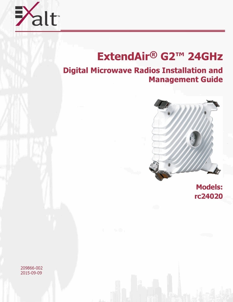
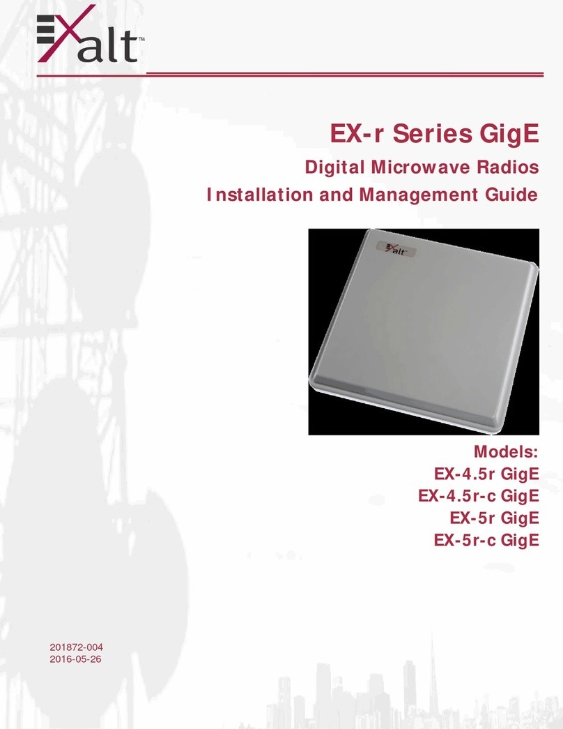
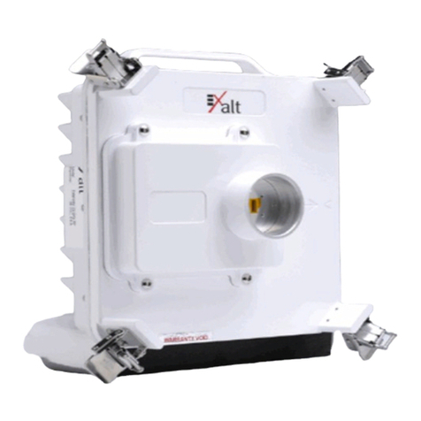
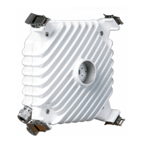
Figure 1 Exalt EX-5r (integrated antenna model)
Generally, the r-Series requires a clear line-of-sight and proper path clearance to achieve a high-
performance, reliable connection. Perform professional path engineering and site planning before
installing this equipment.
The primary focus of this document is the installation and maintenance of the digital microwave
radio, and assumes that path engineering and site planning has already been performed. Please
refer to the Exalt document, Guidance for Engineering and Site Planning of Terrestrial
Wireless Links, for detailed information on these activities.
The EX-5r utilizes radio frequencies in the range of 5250 to 5850 MHz. In most countries these
frequency bands are considered as ‘license-exempt’ or ‘unlicensed.’ This means that virtually
any user may use these frequencies freely, without paying for access, or any type of pre-
notification, post-notification or registration. As a result of this designation, users may also move
or change these systems at any time, with significant flexibility to the location, orientation and
configuration of the system. However, due also to this designation, there may be uncontrolled
interference from other similar devices that occupy this spectrum. In these cases, it is up to
engineering and maintenance personnel to design the system with existing and future
interference sources in mind, recognizing that there is a chance that the interference conditions
could be very dynamic, and outages may occur on the system as a result, and that, in some very
rare cases, the system may cause interference into another system and may be required to be
disengaged or modified/re-oriented to eliminate the interference.
If the spectrum in your country is designated as ‘license-exempt’ or similar, this does not infer
that the installer may configure the system in any manner at any location. In most cases, there
are regulations, or device-based conditions that limit the use of the device, such as maximum
gain antenna, antenna types and maximum output power, as well as, in some cases, application
limits, limited geography of use, and other unique regulations. The link design engineer and/or
professional installer must determine these limitations and engineer/install the system
within the confines of all local regulations. Also, it is required to examine any regulations that
may apply to peripheral equipment, installation and cabling of the system that may be regulated
for human safety, electrical code, air-traffic control, and other safety-related categories.

Exalt Communications, Inc.
r-series Installation and Management Manual
5000007 (ETSI) 3
2007-02-12 (draft)
In certain countries, the spectrum for this product is NOT considered to be license-exempt. In
these cases, there may be additional regulatory requirements concerning the location, frequency,
power, orientation, configuration, and other aspects of the system, including, in some cases, a
need for link registration, coordination, and fees that may apply to the system usage. Please
consult your local regulatory organization(s) to determine usage requirements.
The EX-4.9i utilizes frequencies in the 4940-4990MHz range, and is typically a licensed band
reserved for use by Public Safety agencies and applications. This band is not generally available
outside of North America.
In almost all cases, either for license-exempt or other designation, the product itself must be
authorized for use in your country. Either Exalt or Exalt’s agent must have applied for
certification or authorization to allow the sale and deployment of the system within the country.
It is also possible that only certain versions or configurations of the device are allowed within a
particular country. Please contact Exalt or your authorized Exalt representative for information
pertaining to your country.
It is the (professional) installer’s responsibility to ensure that the radio
system is implemented in a legal fashion. Exalt is not liable for any unsafe or
illegal installations.
Basic Features
The r-Series Digital Microwave Radio is intended for all-outdoor mounting. It is accompanied
with an indoor-mounted power injector. In some cases, the EX-5r may also be mounted indoors
or in an enclosure. Depending on the configuration purchased, the associated antenna is either
integrated as part of the unit or connected separately.
For the integrated antenna model, the entire unit is typically mounted on a tower or rooftop mast
structure, with Ethernet/Power and other optional interface cables running from the unit location,
through a structure penetration, and to the power injector and connected communications
equipment.
For the external antenna model, the unit is typically mounted very close to the external antenna
to minimize RF cabling and associated losses. Alternatively, the unit may be mounted at an
easily-accessible location with longer RF cabling to the antenna. Proper lightning or surge
suppression devices and associated grounding are required for all connections.
This manual suits for next models
8
Table of contents
Other Exalt Radio manuals

Exalt
Exalt ExtendAir r5015 Programming manual
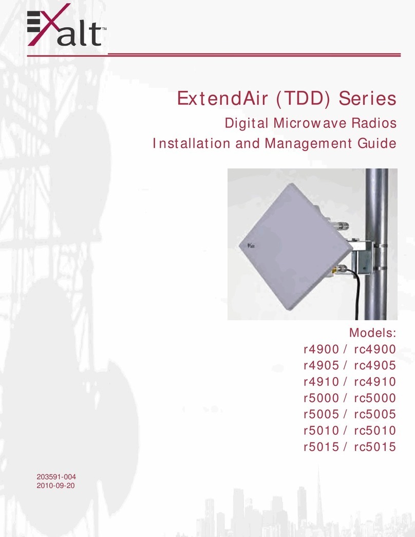
Exalt
Exalt ExtendAir r4900 Programming manual

Exalt
Exalt EX-5r GigE Instruction Manual

Exalt
Exalt ExtendAir series User manual

Exalt
Exalt EX-5i Lite Instruction Manual

Exalt
Exalt r5050 Series Programming manual
Exalt
Exalt EX-2.4i Lite Programming manual
Exalt
Exalt EX-5i-DS3-GigE Programming manual
Exalt
Exalt S Series Programming manual
Exalt
Exalt ExtendAir eMIMO r5050 Series User manual
