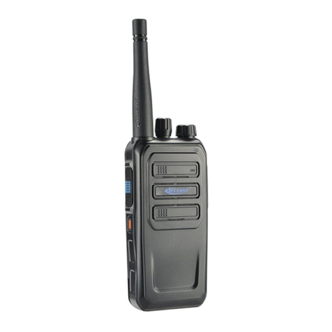
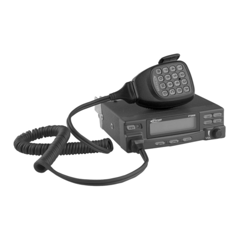
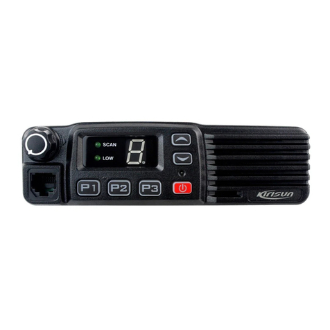
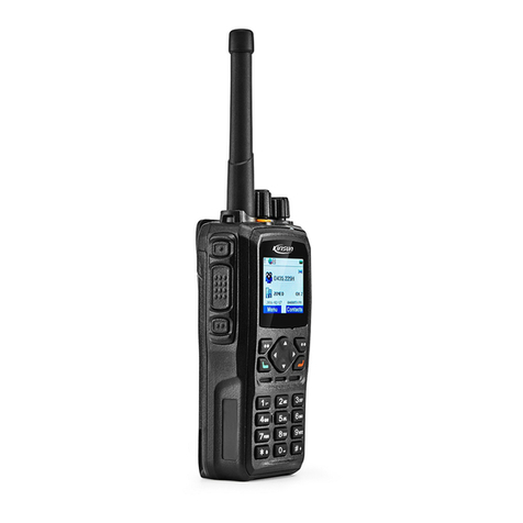
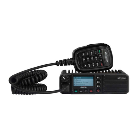
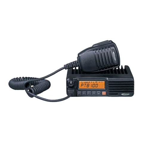
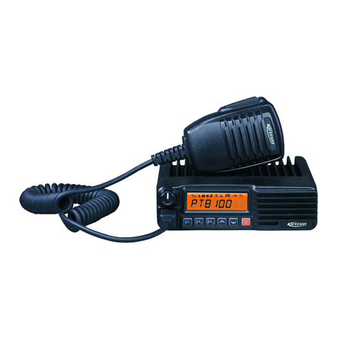
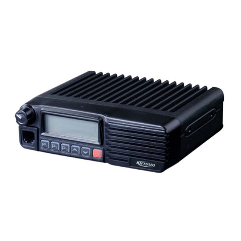
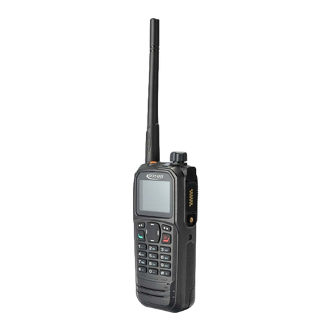
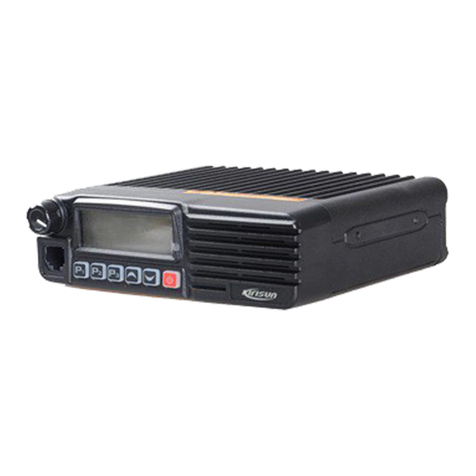
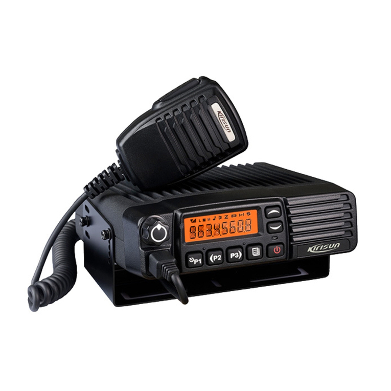
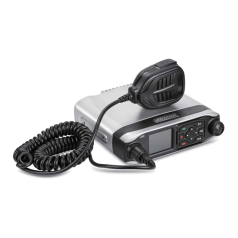
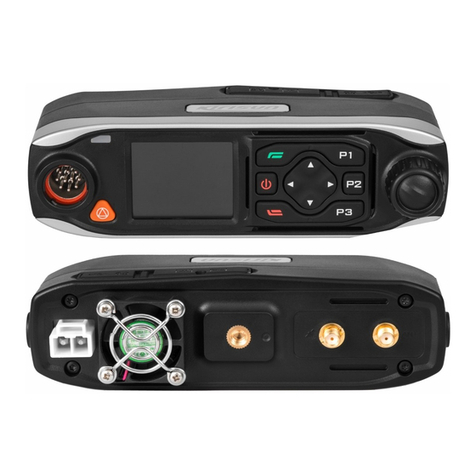
Kirisun FM540 User manual

FM540 Service Manual
FM540 㔤؞ሱ䶒
I

FM540 Service Manual
Contents
1.Overview ......................................................................................................................................................1
1.1. Scope.......................................................................................................................................................................1
1.2. Safety Precaution...................................................................................................................................................1
2.External Views and Key Features .............................................................................................................2
2.1 Front Panel..............................................................................................................................................................2
2.2 LCD Display............................................................................................................................................................3
2.3 Rear Panel...............................................................................................................................................................4
2.4 Microphone (Handheld).........................................................................................................................................4
3.Circuit Description......................................................................................................................................6
3.1 Overview..................................................................................................................................................................6
3.2 Frequency Composition of Circuit........................................................................................................................6
3.3 RX Principle.............................................................................................................................................................7
3.4 TX Principle.............................................................................................................................................................8
3.5 Principle of Frequency Synthesizer.....................................................................................................................9
3.6 Audio Processing Circuit.....................................................................................................................................10
3.7 Power Supply........................................................................................................................................................10
3.8 MCU Unit...............................................................................................................................................................11
3.9 Semiconductor Description.................................................................................................................................13
4.Feature Description and Parameter Settings ........................................................................................19
4.1 TOT(time-out-timer) .............................................................................................................................................19
4.2 Channel Scan .......................................................................................................................................................19
4.2.1. Carrier Control Scan............................................................................................................................19
4.2.2. Scan Revert Channel..........................................................................................................................20
4.3 Kill and Unkill.........................................................................................................................................................20
4.4 Emergency............................................................................................................................................................20
4.5 Feature and Parameter Settings........................................................................................................................21
5.Assembling and Disassembling..............................................................................................................22
5.1 Exploded View......................................................................................................................................................22
I
FM540 Service Manual
5.2 Maintenance and Disassembling Description..................................................................................................24
5.2.1. RF-PCB Disassembling Description ...................................................................................................24
5.2.2. Key-PCB Disassembling Description..................................................................................................26
6.Test and Modulation .................................................................................................................................27
6.1 Test and Modulation Method ..............................................................................................................................27
6.1.1. Parts Required for Modulation.............................................................................................................27
6.1.2. Manual Modulation..............................................................................................................................27
6.1.3. Modulation by Computer.....................................................................................................................28
6.2 Radio Test..............................................................................................................................................................29
7.Major Technical Performance and Specifications.................................................................................30
7.1 General Specifications.........................................................................................................................................30
7.2RX Specification...................................................................................................................................................30
7.3 TX Specification....................................................................................................................................................31
8.Service and Test Equipment....................................................................................................................32
9.Troubleshooting........................................................................................................................................32
Appendix 1 Acronyms..................................................................................................................................34
Appendix2 Material List˄Electrics136-174MHz˅....................................................................................35
Appendix 3 Material Specification(Electronical Parts 400-470) ..............................................................55
Appendix 4 Material Specification (Stucture)............................................................................................74
Figure 1 FM540-01Mainboard Schematic Diagram(136-174MHz).........................................................79
Figure 2 FM540-01 Top Layer Position Diagram(136-174MHz).............................................................86
Figure 3 FM540-01Bottom Layer Position Diagram(136-174MHz)........................................................ 87
Figure 4 FM540-02 Mainboard Schematic Diagram(400-470MHz)........................................................88
Figure 5 FM540-02 Mainboard Top Layer Position Diagram˄400-470MHz˅..................................... 95
Figure 6 FM540-02 Mainboard Bottom Layer Position Diagram˄400-470MHz˅..............................96
Figure 7 FM540 KEY Board Schematic Diagram....................................................................................97
Figure 8 FM540KEYTop Layer Position Diagram...................................................................................98
Figure 9 FM540KEY Bottom Layer Position Diagram............................................................................99
II

FM540 Service Manual
1.Overview
1.1.Scope
This manual is intended for the maintenance & repair of FM540 and used by engineers and professional
technicians trained by Kirisun. Dada changes in this manual may occur with the improvement of technology.
To get the latest technology information, please contact us or your local distributors.
Please read this manual carefully before any maintenance or repair.
1.2.Safety Precaution
Please follow the instructions below to avoid fire or damage to radio:
Maximum continuous working time for transmitingis 1 minute and 4 mniutes for receiving. Long
transmitting or continuous operationon high power mode may cause overheat on the back of the
device.
Do not disassemble the device in any condition.
Do not expose the radio under direct sunlight for long time or put it near any heating device.
Avoid putting the radio in dusty, humid or water-splashing environment or on uneven surface.
if it is smoking or leaking unusual smell, cut off electricity immediately and contact local Kirisundealer.
Do not use 24V battery as it is designed to use 13.8V DC power supply.
Page 1 of 99

FM540 Service Manual
2.External Views and Key Features
2.1 Front Panel
No. Part Name No. Part Name
1 Microphone/Programming Port 2 Volume Control Knob
Rotate the knob toadjust the volume
3 LCD Display
Refer to “LCD Display” section 4 P1 Key (programmable key)
5 P2 Key (programmable key) 6
LED Indicator
Red indicator glows: transmitting.
Red indicator flashes: emergency,
power-on self-test failure or program
auto upgrade failure.
Green indicator glows: signals are being
received or channel activities are
detected.
Orange indicator flashes: it is in call
hang time (digital).
Green indicator flashes: scanning.
7 Speaker 8 P3 Key (programmable key)
9
power on/off Button
Press (at least 2
seconds) the button to
power on/off the radio. 10 Return Key
Press the key to return
11 Down Key 12 Up Key
13 Enter Key
Page 2 of 99

FM540 Service Manual
2.2 LCD Display
Icon Description
Signal strength indicator. The signal gets stronger with more signal bars.
Unread Message
Full Inbox
The current channel is scanning
High Power
Low Power
Analog Channel
Digital Channel
Emergency state (except secret alarm) or an emergency alarm is received.
Private Call
Group Call
All Call
Transmitting
Receiving
The current digital channel is encrypted
Talkaround
Page 3 of 99

FM540 Service Manual
2.3 Rear Panel
No. Part Name No. Part Name
1 Antenna Port 2 Power Port
3 External Speaker Port
2.4 Microphone (Handheld)
No. Part Name
1 PTT Key
Press the key to transmit and release to receive.
ķĸĹ
Page 4 of 99

FM540 Service Manual
2 *Key
Enter “*”.
3 # Key
Switch input method.
4 Enter Key
Programmable key. Set as menu navigation enter key by default.
5 Up key
Programmable key. Set as Up Key by default.
6 Down Key
Programmable key. Set as Down Key by default.
7 Return Key
Programmable key. Set as Return Key by default.
8 MIC
Press ǏPTTǐkey and speak to the mic to transmit.
9 Digital Keypad (09)
10 keys in total. Press the key to enter the number or edit the text message or new contact.
Page 5 of 99

FM540 Service Manual
3.Circuit Description
3.1 Overview
This is a FM device.
3.2 Frequency Composition of Circuit
Figure 3-1 Circuit Schematic
The receiver applies secondary mixing technology.The first intermediate frequency is 51.65MHz and the
second one is 450 kHz. The first local oscillator is generated by the frequency synthesizer while the second
one is generated by quadruple frequency of12.8MHz. Txsignal is generated by the frequency synthesizer
and the reference frequency of the frequency synthesizer is generated by TCXO.
ANT SW RF
AMP
PA
AMP TX
AMP PLL
VCO
IF SYSTEM
X4
multiply
TCXO
12.8MHz
51.65MHz
MCF
CODEC
AF
AMP
MIC
CF
450KHz
ANT
MIXER
Page 6 of 99

FM540 Service Manual
3.3 RX Principle
Figure 3-2 RX Schematic
•Front End of Receiver
The signal received will passTx-Rx switch controller andalso the BPF composed of LC of two levels
toremove undesired out-of-band signals, then it will be sent to the LNA(low noise amplifier) composed of
Q18 and other peripheral components for amplification
The output of LNApasses the BPF composed of LC of three levels to further remove undesired out-of-band
signals and is then sent to the first-level frequency mixer Q19.
•The First Mixer
The signal from LNA mixes with the first local oscillator signal from the frequency synthesizer to generate
the first intermediate frequency (51.65MHz) signal.
•IF Circuit
The first IF signal passes the crystal filter (XF700) to remove the signals from the adjacent channel or other
channels.
The first IF signal from the crystal filter is sent to the IF- processing IC(IC6, GT3136) after being amplified
by the first IF amplifier (Q20).
IF IC includes secondary mixer, IF amplifier, limiter, frequency detector, noise amplifier and audio low pass
filter.
The 12.8MHz signal from X1 passes Q300 and the peripheral circuit for amplification and then the second
local oscillator of 51.2MHz is acquired. The second oscillator (51.2MHz) mixes frequency with the first IF
ANT SW BPF
1st local
osc
BPF
MCF
IF AMP
Q20
IF DET
450K
CODEC
AF PA
D3 D37 D36
D11
MIXER
Q19
XF700
51.65MHz
U6IC7
ANT
X1
Multiply
Q11
TCXO
MCU
IC19
PC/TV
Q18
RF AMP
Page 7 of 99

FM540 Service Manual
signal (51.65MHz) in IC6 to generate the second IF signal (450kHz). The second IF signal will be amplified
and limited in IC700 and after being filtered by CF1 crystal filter (450kHz), it will be demodulated by IC700
and audio signal will be output.
•Squelch Circuit
The signal demodulated by IC6 is sent to the noise amplifier, and the amplified noise signal is sent to Q21
for further amplification and to D21 for wave detection to generate DC electric level, which is sent to the
MCU control squelch circuit. The voltage is inversely proportional to the input signal.
3.4 TX Principle
Figure 3-3 Power Amplification and Antenna Schematic Diagram
The modulated RF signal from VCO is sent to Q600 for power amplification after being amplified by Q1, Q2,
and Q5.
IC4 is controlled by MCU APC circuit to change the grid bias voltage, easily controlling the output power of
the transmitter.
•APC (automatic power control) Circuit
D9 and D10 are standing wave current detection. IC4 is power amplifier.
If the output power of the transmitter is too high, the power amplifier current increases and the output
voltage from D9 and D10 will go up, which causes the VGG offset voltage on IC1 decreases and thus the
output power of the transmitter decreases. Vice versa. In this way, the output power of the transmitter stays
stable in different working environment.
MCU sets the power by changing the voltage input to IC4.
8T
SW
D2 DRIVE AMP
Q5 FINAL AMP
IC1
ANT SW
D3,D37 LPF
APC
IC4
APC
8T
8T
8T
D9,D10
RX BPF
VGG
VSWR
Page 8 of 99

FM540 Service Manual
3.5 Principle of Frequency Synthesizer
Figure 3-4Diagram of Frequency Synthesizer
This radio applies PLL frequency synthesizer.The frequency synthesizer consists of reference oscillator,
voltage controlled oscillator (VCO), programmable frequency divider, phase comparator and low pass filter.
Q6, D1, D4, D5, D6 and other resistor-capacitor components compose TX VCO unit. D8 is the modulation
circuit of TX VCO.
Q12, D4, D16, D17, D18 and other resistor capacitor components compose RX VCO unit.
IC3 (MB15E03) is PLL integrated circuit, which contains programmable reference divider, programmable
divider, phase comparator, charge pump and so on. R54, C113, R55, R57, C117, R51, C109 and so on
compose loop filter.
The reference frequency is offered by X1 (TCXO, 12.8MHz).
The reference frequency from TCXO(temperature controlled crystal oscillator) is divided by the
programmable reference divider in IC3 to generate reference frequency of 5kHz or 6.25kHz(based on the
set channel frequency and controlled by MCU).
The oscillation frequency from VCO is sent to IC3 after being multiplied by second multiplier circuit, and will
then be compared to reference frequency after being divided by programmable divider to get error signal.
The error signal will be filtered by the low pass filter and sent to VCO to change the oscillation frequency.
When the VCO frequency reaches the set value, VCO is locked.
Loss of Lock Detection: when PLL loses its lock, IC3 pin14 outputs low electric level signal to MCU and
MCU controls the transmitter to forbid the transmitting and sound alert. When locked, IC3 pin14 outputs
high electric level.
15
PLL
DATA
LPF
Q12
RX VCO
PLL
DATA
Q1
BUFF AMP
12.8MHz
TCXO
X1
IC3
PLL IC
Q6
TX VCO
Q25,U2
SW
Q2
RF AMP
LPF
MCU
IC12
½ FREQ
Page 9 of 99

FM540 Service Manual
3.6 Audio Processing Circuit
Figure 3-5 Frequency Synthesis Diagram
•MIC Signal Processing
The audio signal from MIC is sent to U6 for A/D audio switch and sent to U1 SCT3252 for internal adio
encoding/decoding, communication protocol processing, channel coding modulation. Afterwards, MOD2,
MOD1 are output through two separate paths from U6 and sent separately to TCXO and VCO for two-point
modulation. 4FSK modulation signal is output in digital status and sine wave signal is output in analog
status.
•RX Audio Signal Processing
The audio signal demodulated from IC700 is sent to U6 for A/D audio switch and then be processed by U1
SCT3252.After audio processing, communication protocol processing and DSP, the signal is sent to U6 for
D/A switch and output to audio power deviceU800(TDA2822) for amplification, motivating the speaker to
sound.
Squelch Circuit: demodulated and output byIC700; it passes filter circuit and the noise will be removed from
demodulated signal and amplified by Q700; after detection by D701, it will be sent to MCU. MCU identifies
the noise volume and controls the squelch.
Speaker Impedance: 16Ω.
Notes:
•Any terminal of the speaker must not be attached to the ground!
•The emergency alert tone is not controlled by volume.
3.7 Power Supply
This radio applies 13.8V battery. The transmitter power amplifier circuit (IC1) and the receiver audio
processor (IC7) directly use the battery for power supply with other circuits using 5V for power supply.
Q38: 8T switch; controlled by MCU. 8T supplies power for the transmitter front end.
Q40: 8R switch; controlled by MCU. 8R supplies power for receiver RF amplifier, mixer, IF processor, and
other units.
FM receiver
FM modulatorPA
TR
SW
Host MCU
4FSK Protocol
stack
Voice
coder
U6 CODECL
U6 CODECR
ANT
SCT3252
U1
IC2
SPK
MIC
Page 10 of 99

FM540 Service Manual
IC1: 5C switch. 5V circuit is controlled by MCU. 5C supplies power for frequency synthesizer.
IC8, IC102: 3V and 1.2V DC\DC voltage stabilizing circuit; supplies DC current for U1 (SCT3252F).
IC9: 8V three-terminal voltage stabilizing circuit.
3.8 MCU Unit
MCU unit
MCU unit controls the operation of each unit and realizes all the features on the device:
•Communication with PC
•Saves the status data
•Control PLL to generate RX/TX local oscillation frequency
•Acquires the current channel status
•Controls LED status indication
•Controls power supply of each unit
•Check action from each feature key
•Generates CTCSS signal
•GneratesDCS signal
•Generates power control signal
•Completes CTCSS decoding
•Completes DCS decoding
•Squelch detection and control
•Control the content of voice prompt
Memorizer (E2PROMˈAT24LC512BN)
It stores channel data, CTCSS/DCS data, feature configuration data and parameter adjustment data.
CTCSS/DCS Signal Encoding and Decoding
The CTCSS/DCS signal generated by MCU is sent separately to VCO and TCXO for modulation.
The CTCSS/DCS signal from the receiver is sent to MCU for decoding. MCU will try to identify the
CTCSS/DCS signal received which is the same as the device and the speaker will be turned on if it does.
CTCSS
CTCSS (continuous tone control squelch system) is a squelch control system modulated on the carrier with
the CTCSS signal being the pilot frequency
If the CTCSS feature is set, the conversation is enabled only when the CTCSS frequency from the receiver
and transmitter is the same to avoid interference from other signals.
Page 11 of 99

FM540 Service Manual
39 groups of standard CTCSS frequency of this radio are available. See Chart 1.
CTCSS signal is generated by MCU (PWM wave form), and it is sent to VCO for modulation after being
filtered by the low pass filter composed of RC for eliminating the frequency higher than 300Hz.
Chart 3-1 CTCSS Frequency Chart
No. Frequency [Hz] No. Frequency [Hz] No. Frequency [Hz] No. Frequency [Hz]
1 67.0 11 94.8 21 131.8 31 186.2
2 69.3 12 97.4 22 136.5 32 192.8
3 71.9 13 100.0 23 141.3 33 203.5
4 74.4 14 103.5 24 146.2 34 210.7
5 77.0 15 107.2 25 151.4 35 218.1
6 79.7 16 110.9 26 156.7 36 225.7
7 82.5 17 114.8 27 162.2 37 233.6
8 85.4 18 118.8 28 167.9 38 241.8
9 88.5 19 123.0 29 173.8 39 250.3
10 91.5 20 127.3 30 179.9
DCS Signal
DCS (digital code squelch) is a continuous numerical code which is modulated along with the speech signal
on the carrier to control the squelch. If the DCS feature is set, the speaker is on only when the same DCS
code is received to avoid the unnecessary signal interference.
83 kinds of standard code of this radio are available. See chart 3-2.
DCS signal is generated by MCU (PWM wave form), and it is sent to VCO and TCXO for modulation after
being filtered by the low pass filter composed of RC for eliminating the frequency higher than 300Hz. VCO
modulates the high frequency of DCS signal and TCXO modulates the low frequency of DCS signal.
CTCSS/DCS signal from the receiver is sent to MCU for decoding. MCU will try to identify the CTCSS/DCS
signal received which is the same as the device and the speaker will be turned on if it does.
Chart 3-2 DCS Encoding Chart
023 114 174 315 445 631
025 115 205 331 464 632
Page 12 of 99

FM540 Service Manual
026 116 223 343 465 654
031 125 226 346 466 662
032 131 243 351 503 664
043 132 244 364 506 703
047 134 245 365 516 712
051 143 251 371 532 723
054 152 261 411 546 731
065 155 263 412 565 732
071 156 265 413 606 734
072 162 271 423 612 743
073 165 306 431 624 754
074 172 311 432 627
3.9 Semiconductor Description
Chart 3-3 Microprocessor (M30620) Port Description
Pin No. Port Name Input/ output Function
1 VCCN D/A Output Reference frequency adjustment output
2 TONE_OUT D/A Output DTMF/Tone output, beep output
3 HSDI I Tone decoding input
4 EPDT I/O EEPROM data input/ output
5 EPCK O EEPROM clock
6 BYTE I GND
7 CNVSS I GND
8 BSHIFT O Clock beat frequency control
9 SV O Min. volume control
10 RESET I CPU reset input
Page 13 of 99

FM540 Service Manual
11 XOUT O CPU clock output
12 VSS - GND
13 XIN I CPU clock input
14 VCC - +5V
15 NC I +5V
16 PTT I PTT key
17 RD NC I NC
18 NC I NC
19 NC O NC
20 NC I/O NC
21 NC O NC
22 S_CS O FLASH data output
23 S_SO I FLASHdata output
24 NC O NC
25 S_SCK O FLASH data output
26 PC/TV O TX power,receving frequency band voltage tunning
27 S_SI - FLASH data output
28 NC O NC
29 TXD O TXD1 output
30 RXD I RXD1 input
31 C_CLK - Emulator interface
32 C_BUSY O Emulator interface
33 TXD0 O NC
34 RXD0 I NC
35 AFCO_1 O RX/TX audio power amplification control pin
36 NC O NC
Page 14 of 99

FM540 Service Manual
37 RX SW O Receiver VCO switch
38 TX SW O Transmitter VCO switch
39 C_CE - Emulator interface
40 PLL UL I Phase-locked loop loss of lock check pin
41 PLL STD O Phase-locked loop enabling control
42 PLL DATA O Phase-locked loop data output
43 PLL CLK O Phase-locked loop clock
44 NC - NC
45 SCT3252MOD O Data output pin
46 GREEN_LED I RX status indicator
47 RED_LED I TX status indicator
48 8TC I 8T control pin
49 8RC I 8R control pin
50 SBC I SB control pin
51 INTO O Baseband wake-up pin
52 PLLBYOPASS O Baseband bypass pin
53 PLLSEL2 O PLLHigh/low Selection
54 HCSN O Baseband Chip Selection
55 HWRN I Baseband data writing enable
56 HRDN O Baseband data reading enable
57 HOBIB O Baseband data check
58 RSTN_3252 O Baseband reset
59 NMI - Baseband wake-up foot
60 ACC - +5V
61 PIO3 - Baseband wake-up foot
62 VSS - GND
Page 15 of 99

FM540 Service Manual
63 HPI_DATA0 - HPI address bus
64 HPI_DATA1 - HPI address bus
65 HPI_DATA2 I HPI address bus
66 HPI_DATA3 I HPI address bus
67 HPI_DATA4 I HPI address bus
68 HPI_DATA5 I/O HPI address bus
69 HPI_DATA6 I/O HPI address bus
70 HPI_DATA7 I/O HPI address bus
71 SI/D7 I LCD data output
72 SCL/D6 I LCD data output
73 A0 I L LCD data output
74 /RST I LCD reset pin
75 /CS1 I LCD data output
76 NC O NC
77 NC O NC
78 BASEBAND_C O Baseband power control pin
79 D0 O DTMF data pin
80 D1 O DTMF data pin
81 D2 O DTMF data pin
82 D3 O DTMF data pin
83 DV O DTMF data pin
84 NC O NC
85 NC O NC
86 HOOK - HOOK control pin
87 BEEP_C I Reverse detection input
88 BATT I Voltage check input
Page 16 of 99

FM540 Service Manual
89 RSSI I Receiving filed intensity signal input
90 BUSY I Squelch voltage check input
91 VOL_DET I VOL_DET
92 PF2 I PF2
93 PF1 I PF1
94 AVSS - GND
95 TEMP - TX temperature detection
96 VREF - +5V
97 AVCC - +5V
98 W/N - W/N switch pin
99 MD I Speaker micdata input pin
100 TGSW O TX control pin
Chart 3-4 Semiconductor Description
Position Mark Model Feature Description
IC202 PST9140NR MCU reset circuit
IC3 MB15E03 Frequency synthesizer
IC4 NJM2904 APC, volatage comparison, driver
IC6 GT3136 Receiver second
local oscillator, second IF amplification,
amplitude limiting, demodulation, noise amplification.
IC204 NJM2902 Receiver demodulation signal amplification and filtering.
IC1 M30620 MCU
IC200 AT24C512C E2PROM, stores channel frequency data, feature settings and
modulation status parameters.
IC7 TDA1519C Receiver audio power amplification
Q12 2SC3356 RX VCO oscillator tube
Q1 2SC5108 VCO buffer amplifier
Page 17 of 99
Other manuals for FM540
1
Table of contents
Other Kirisun Radio manuals

Kirisun
Kirisun PT4208 User manual

Kirisun
Kirisun PT8100 -01 User manual

Kirisun
Kirisun PT8000 User manual

Kirisun
Kirisun DP770 User manual

Kirisun
Kirisun FP420 User manual

Kirisun
Kirisun PT8000 User manual

Kirisun
Kirisun DP405 User manual

Kirisun
Kirisun DM588-02 User manual

Kirisun
Kirisun TM840 User manual

Kirisun
Kirisun FM540 User manual

Kirisun
Kirisun V688-02 User manual

Kirisun
Kirisun TM840 User manual

Kirisun
Kirisun M50 User manual

Kirisun
Kirisun DP990 User manual

Kirisun
Kirisun TM840 Instruction manual

Kirisun
Kirisun FP460 User manual

Kirisun
Kirisun PT810003 User manual

Kirisun
Kirisun DM588-01 User manual

Kirisun
Kirisun PT8200 User manual

Kirisun
Kirisun DM588 User manual