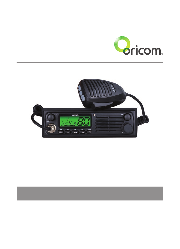
Oricom UHF098 User manual

Keep this user guide for future reference. Always retain your proof of purchase in case of
warranty service.
www.oricom.com.au
Operating Instructions
UHF098 80 Channel UHF Citizen Band Radio

When a narrowband radio receives a transmission from an older wideband radio the speech may sound loud and
distorted – simply adjust your radio volume for the best listening performance. When an older wideband radio receives
a signal from a new narrowband radio the speech may sound quieter - simply adjust your radio volume for best
listening performance. When operating a narrowband radio or Channel 41 - 80 interference is possible from wideband
radios transmitting on high power or on adjacent frequency.
The issues described above are not a fault of the radio but a consequence of mixed use of wideband and
narrowband radios.
This unit complies with all relevant Australian
and New Zealand approval requirements
AS/NZS 4365:2011

3
Controls and Indicators .................................................................4
Installation....................................................................................7
Operations..................................................................................10
UHF CB channels and frequencies ..............................................26
Express Warranty (Australia) .......................................................30
Table of contents
Need Help?
If you need assistance setting up or using your Oricom product now or in the future,
call Oricom Support.
Australia (02) 4574 8888
www.oricom.com.au
Mon-Fri 8am – 6pm AEST
New Zealand 0800 67 42 66
www.oricom.co.nz
Mon-Fri 10am – 8pm NZST

4
Controls and Indicators
Front View
612 7891011
1 52
4
3
1. Rotary On/Off switch and Volume control
2. LCD display
3. RX/TX LED indicator
4. Speaker
5. Rotary Squelch control
6. Rotary Channel control
7. Triple watch/Menu
8. Memory recall/Memory write
9. Monitor On/Off/Tone squelch On/Off
10. Priority channel recall/Key lock
11. Scan/Memory skip
12. Microphone connector

5
Controls and Indicators
Rear View of Radio
1. Antenna connection
2. 3.5mm external jack for optional 8 ohm speaker
3. Power supply connection
Microphone
1. Push to talk
2. Channel Down (P1)
3. Channel Up (P3)
4. Instant Channel (P2)
243
1
INS: Priority channel recall
You can select a priority channel in the
menu under the “PRI” setting.
Your can recall priority channel by pressing INS button.
123

6
Controls and Indicators
LCD Icons & Indicators
1. Memory address
2. Monitor on
3. Duplex on
4. Scrambler on
5. CTCSS on
6. DCS on
7. CTCSS or DCS channel display
8. Channel display
9. Status display
10. Triple watch on
11. Beep tone on
12. Roger Beep tone on
13. Signal strength & TX meter
14. Memory channel
15. Priority channel on
8
15
1 2 345
12 13
6 7
10 11 14
9

7
Installation
Installation
Box Contents
1 X UHF098 CB RADIO
1 X Microphone
1 X DC Power cord with inline fuse
1 X Mounting bracket with mounting screws
1 X Microphone hanger
1 X DIN mounting kit
1 X User guide
Using the DIN Kit
The UHF098 comes complete with a DIN kit for mounting in a vehicle dash
board.
Installation
When installing your radio in your vehicle, check that during installation
you do not damage any wiring or vehicle components that may be
hidden around the mounting position.
Ensure the installation does not interfere with the operation of
the vehicle and meets all regulatory and safety requirements for
accessories fitted to your vehicle.
For optimum performance your radio needs to be installed correctly. If
you are unsure about how to install your radio, we suggest you have
your radio professionally installed by a UHF specialist or Auto electrician.
When installing the radio, avoid mounting it close to heaters or air
conditioners. Never press the PTT button before connecting the antenna
to the radio.

8
Installation
Wiring Methods
There are two possible wiring congurations for connecting to the vehicles
power supply.
A. Radio stays ON when the ignition is switched OFF
Connect the radio's negative (black) lead to the vehicle chassis, or directly to the
battery's negative terminal.
Connect the radio's positive (red) lead via the 3 Amp fuse to the battery's
positive terminal. Alternatively, the positive lead could be connected at the fuse
box at a point that has DC Power continuously available (preferably the battery
side of the ignition switch) via the 3 Amp fuse.
B. Radio turns OFF with the ignition switch
Connect the radio's negative (black) lead to the vehicle's chassis, or directly to
the battery's negative terminal.
The radio's positive (red) lead should connect to an accessory point in the
vehicle's fuse box via the 3 Amp fuse.

9
Antenna information
The antenna (not supplied) is of critical importance to maximize your output
power and receiver sensitivity.
A poorly installed, inferior quality antenna, or one not designed for the correct
frequency band, will give poor performance. You should only purchase an
antenna designed for the 477MHz frequency band.
Antenna installation
1. If the antenna is tted with an FME connector you will require a FME to
PL259 adapter to t the connector on the rear panel of the radio.
2. To obtain maximum performance from the radio, select a high quality antenna
and mount it in a good location.
Never press the PTT before connecting the antenna to the radio.
Optional accessories
If required, you may install an external (8 ohm, minimum 5W power) speaker
tted with a 3.5mm plug (not supplied).
Installation

10
Operations
Operations
Power On/Off
Rotate the power switch in a clockwise direction to turn the unit on, adjust the
volume to a comfortable level, rotate the Power Switch counter clockwise until
it clicks to turn off the power. At power on, the current applied DC voltage is
displayed numerically as shown below. Special over and under voltage detection
circuitry protects the radio and warns of excessive voltage conditions by the LCD
flashing the 7 backlight colours.
Squelch
To adjust the level of squelch use the rotary SQL control. Turning the control
counter clockwise reduces the amount of squelch, and turning clockwise
will increase the amount of squelch. To reduce the signals that you can hear,
increase the squelch, to hear more signals which may include weak signals
decrease the squelch.
To Select a Channel
To select a channel rotate the CH control clockwise or counter clockwise to the
desired channel.

11
Operations
Transmitting
Note: Before transmitting on any channel, listen to check the channel is not already
in use.
Select the desired channel. Press the PTT button on the microphone and speak
normally into the microphone. Hold it approx.7 cm from your mouth. Release the PTT
button to end the transmission and listen for a reply.
Transmitting range
The talk range depends on the environment and terrain, it will be affected by
concrete structures and heavy foliage.
Optimal Range
Outdoors Flat, open
areas
Medium Range
Outdoors Buildings
or trees Also near
residential buildings
Minimal Range Outdoors
Dense foliage or
mountains. Also inside
some buildings
Scanning
The Scan feature allows you to search for active channels automatically.
There are three scanning modes: Open Scan, Priority Scan, Memory Scan
These three scan modes can be selected from the menu.
Open scan
Press Scan/MEM button and scanning starts. The OS sub menu display appears
on the LCD.
The scan direction can be changed at any time by rotating the channel selector
left or right.
This can also be controlled by microphone up and down buttons.
To stop Scan, press Scan/MEM Button or PTT button.
When a signal is found, scanning will stop at that channel to allow the signal to
be heard, then resume scanning when the channel is clear again.

12
Operations
CH 1-2-3-4-5-6-7 ….. 77-78-79-80
Priority scan
With Priority Scan, The radio scans for activity, but in addition, it also inserts
your Priority Channel into the scan sequence.
This means that your Priority Channel will be monitored regularly while scanning
to ensure that no calls are missed. Any signal received on your Priority Channel
will take precedence over any signals received on the other channels.
CH 1-2-3-4-5- PRI CH - 6-7-8-9-10- PRI CH…..76-77-78-79-80
Memory scan
The memory channel Scan feature allows the radio to automatically scan
through 5 memory channels.
The radio scans automatically the 5 memory channels and stops where radio
trafc is detected.
Note: Please program 5 channels of your choice as memory channels.
See instructions on page 16 to save memory channels.
The default channels are shown below.
Memory Memory 1 Memory 2 Memory 3 Memory 4 Memory 5
Location Scan/MEM PRI/LOC MONI/TSQ MR/MW TW/MENU
Channels 1 20 30 40 80

13
Operations
MEM (Remove Memory in Scanning)
You may want to remove a channel from scan due to constant noise, using
CH30 as the example:
1. If you are scanning, stop scan by press SCAN/MEM.
2. Select channel CH30 to skip during scan.
3. Press and SCAN/MEM button for 2 seconds until “SKPon” will appear.
4. Press SCAN/MEM button for scan start.
5. Channel 30 is removed from the scan.
SCAN 28-29-30-31-32…. 77-78-79-80
MEM Off SCAN 28-29-31-32…. 77-78-79-80
Note: To enable a skipped channel to scanning again, select the channel, then
press and hold SCAN/MEM until SKPoF appears.

14
Operations
Priority Channel Recall
You can select a priority channel through the menu in the “PRI” setting.
To recall the priority channel press the PRI/LOC button.
“P” will appear along with the priority channel number.
This priority channel will also be automatically monitored during Priority scan.
Key Lock
To prevent accidental entries, you can lock the key pad.
To enable “Key on” function:
* Press hold “PRI/LOC” button. “KEYon” will then appear when the key lock is
active, a warning beep will be heared if you attempt to press keys.
Note: The PTT and key lock button do not lock.
Warning beep is only active if beep function is turned on.
* To disable the Key lock function.
* Press hold “PRI/LOC” button. “KEYon” will then appear.
Monitor Function
The monitor button is used for temporarily opening the squelch, in order to listen
to signals that are too weak to keep the squelch permanently opened.
For brief listening, press Monitor briey to turn Squelch off, press briey again to
turn Squelch back on.

15
Operations
Selecting the Required CTCSS or DCS Tone
To pre-select the CTCSS tone or DCS on your radio, please refer to the MENU
setting.
Enabling CTCSS or DCS on a channel
If a CTCSS tone has been selected, it can be enabled on individual channels.
Press and hold the MO/TSQ button.
Disabling CTCSS or DCS on a Channel, repeat press and hold MO/TSQ button.
Note: CTCSS and DCS will not operate on channel 5 and 35.
Memory recall channels
To access memorized channels simply press the “MR/MW” button then one of
the M1 to M5 buttons.
Memory Memory 1 Memory 2 Memory 3 Memory 4 Memory 5
Location Scan/MEM PRI/LOC MONI/TSQ MR/MW TW/MENU
Channels 1 20 30 40 80

16
Operations
Memory write channels
The memory write button is used to store a channel in the memory location M1
to M5.
To store channels:
• Select the desired channel with rotary knob.
• Press and hold MR/MW button.
• Select the location you would like to store the channel by pressing
M1, M2, M3, M4 or M5.
Triple Watch Function
Pressing the TW/MENU button activates the Triple watch function.
The Triple Watch feature allows for monitoring of 2 or 3 channels.
The currently displayed channel and 2 more channels saved in TRI1 and TRI2.
To store the channels in TRI1 or TRI2, select the channels and features CTCSS/
DCS/Duplex on the display then enter menu mode and save the channel in TRI1
or TRI2.
If only one additonal channels is required, then select “Off” in TRI2.
Once Watch is activated, by pressing the TW/MENU button, the TRI1 and TRI2
channels are checked in the following sequence. Main channel is checked for 0.7
of a second, the TRI1 for 0.15 seconds, TRI2 for 0.15 seconds and the back to
the Main channel.
The sequence is repeated until a signal is detected or radio is switched off.
If there is a signal present on TRI1 or TRI2, The radio will wait on that channel
for 5 seconds after the signal is no longer present, then revert to Tri Watch
operation.
Triple Watch can be disabled by pressing any key.

17
Operations
Note: The default value of TRI1 AND TRI2 is off, you must store a channel to use
this feature.
If you try to use it unsaved, LCD will display “Empty”.
Menu Function
The Menu provides a convenient method of customizing some of the radios
functions.
The following menu options are available. Note that some items are only
available on certain channels.
To access the Menu functions:
1. Press and hold the TW/MENU button. The rst menu function is displayed.
2. Briey press the menu button to cycle through each available function.
After the last function has been selected, the cycle automatically exits the menu.
3. Use the up or down channel rotary selector to change the parameters of the
selected function.
4. To exit the menu, press PTT button or press and hold the menu button for
2 seconds.
The following feature can be selected by using the “MENU” button:
1) User selectable 38 CTCSS and 104 DCS codes (CTCSS or DCS cannot be
enabled on channel 5 and 35)
2) Scrambler setting (Off, 1 to 5 different frequencies)
3) LCD backlight colour (7 colour)

18
Operations
4) LCD backlight level (Bright or Dimmer d0 to d5)
5) Duplex On/Off
6) Priority channel memory ( 1 to 80 Channel)
7) Scan mode (Open/Priority/Memory scan)
8) Scan resume time (P5, 5,10,15)
9) Busy channel lockout (On or Off)
10) Key beep tone (On or Off)
11) Roger beep tone (On or Off)
12) Melody call tone (off, 1 to 5)
13) Triple watch sub channel 1 setting (Off, 1-80)
14) Triple watch sub channel 2 setting (Off, 1-80)
15) Squelch tail (On or Off)
16) Programmable key function P1 of microphone (UP/SCAN/PRI/MONI/MR/TW)
17) Programmable key function P2 of microphone (PRI/SCN/MONI/MR/TW)
18) Programmable key function P3 of microphone (DN/SCN/PRI/MON/MR/TW)
19) Software version display
Function Parameter Display Default
CTCSS and DCS
CTCSS 38
CTCSS 01to
DCS 104
Scrambler
1
OffOff
5
Backlight LED colour
Red
Greento
Pu
Bright of LCD
br
Brightto
d0 to D5
Duplex
On
On
Off
Priority CH.
1
11to
80

19
Scan mode
OS
OSPS
MS
Scan resume time
P5
P5to
5,10,15
Busy channel lock
On
Off
Off
Key beep tone
On
Off
Off
Roger beep tone
Off
Off
1 to 5
Melody Call
off
Offto
1 to 5
Triple watch CH 1
1
Off
80
Triple watch CH 2
1
Off
80
Squelch tail
On
Off
Off
Programmble P1
DN
DNto
M1 to M5
Programmble P2
PRI
PRIto
M1 to M5
Programmble P3
UP
UPto
M1 to M5
Software Version Ver. 01Version
Operations

20
Duplex
General
Your radio has a Repeater Access function to allow use of local Repeater stations (if
available in your area). Repeaters are shared radio system installed by interested
parties (clubs, local business etc.) that pick transmissions on specic channels
and re-transmit (or repeat) the received signal to another channel.
Channel 2
Channel 32
Channel 2
Channel 32
Repeater Station
The Repeater Access function can be set (from channel 1 to 8 and 41 to 38)
used by local repeater stations. When activated, your radio will receive the
Repeater on its specic channel (all repeater outputs are on channel 1 to 8
and 41 to 48) but transmits to the repeater channel 31 through to 38 and 71
through to 78. (Factory default is set to On for all repeater channels).
e.g.
CH01 on Duplex mode will receive on CH01 but transmit on CH31
CH02 on Duplex mode will receive on CH02 but transmit on CH32.
If you transmit on CH01 duplex mode, you are actually transmitting on CH31.
The repeater station down converts your signal and retransmits on CH01.
Your transceiver allows you to pre-select Duplex operation individually on each
channel.
CH and Number Simplex mode Transmit/reciever
Frequency (MHz)
Duplex Mode transmit
Frequency(MHz)
1 476.425 477.175 CH31
2 476.450 477.200 CH32
3 476.475 477.225 CH33
Operations
Other manuals for UHF098
1
Table of contents
Other Oricom Radio manuals

Oricom
Oricom DTX4200XDV User manual

Oricom
Oricom UHF088 User manual

Oricom
Oricom UHF030 User manual

Oricom
Oricom UHF080 User manual

Oricom
Oricom PMR795 User manual

Oricom
Oricom DTX4200X User manual

Oricom
Oricom UHF182 User manual

Oricom
Oricom UHF400R User manual

Oricom
Oricom UHF025 User manual

Oricom
Oricom DTX4000 User manual

Oricom
Oricom UHF350DR User manual

Oricom
Oricom DTX4300 User manual

Oricom
Oricom UHF2500 User manual

Oricom
Oricom UHF390 User manual

Oricom
Oricom UHF028 User manual

Oricom
Oricom UHF182X User manual

Oricom
Oricom UHF058 User manual

Oricom
Oricom DTX4200XP User manual

Oricom
Oricom UHF360 User manual

Oricom
Oricom UHF028PNP User manual