Bison SVH-1 User manual

Models
SUBSOILER OPERATOR’S MANUAL
Part No.
4350-2135-01
SVH
SVH
SVH-1 SVH-5/3 SVH-9/5


READ THIS MANUAL carefully to learn how to operate and service your
machine correctly. Failure to do so could result in personal injury or equipment
damage.
THIS MANUAL SHOULD BE CONSIDERED a permanent part of your
machine and should remain with the machine when you sell it.
MEASUREMENTS in this manual are given in both metric and customary U.S.
unit equivalents. Use only correct replacement parts and fasteners.
RIGHT-HAND AND LEFT-HAND sides are determined by facing in the
direction the implement will travel when going forward.
.
INTRODUCTION
4350-2135-01 (Rev. 17/10/12)
!!

TO OUR CUSTOMERS:
Congratulations for acquiring a Bison® product.
We are confident in your excellent decision to purchase Bison®equipment,
and are honored to have you as our valued customer.
Your dealership shall make the technical pre-delivery of your equipment,
and a trained technician shall provide you maintenance and operation
instructions contained in this manual. Get in contact with your dealership
representative if you have questions regarding your equipment or need
specialized help.
We recommend that you read this manual before operating the equipment.
Therefore, the time you take to learn about all maintenance features,
adjustments and recommendations will result in the long, efficient life of
your equipment.
This equipment is covered by a warranty duration provided by your Bison®
authorized dealer at the purchase or technical delivery of same.
Bison®is a Brand of Tecnomec Agrícola, S.A. de C.V., Aguascalientes,
México.

GENERAL INDEX
INTRODUCTION
GENERAL INFORMATION
SPECIFICATIONS
SAFETY RULES
OPERATION
MAINTENANCE
TROUBLESHOOTING
ASSEMBLY
PARTS INDEX
BOLT TORQUE CHART
WARRANTY
!!
01
06
07
11
14
16
17
26
36
39

OPERATOR’S MANUAL
If this manual is lost or destroyed
a new copy can be requested to:
TECNOMEC AGRICOLA S.A. DE C.V.
Carr. a Paso Blanco, Km 2 No. 400
Col. Vista Hermosa, Jesús María
Aguascalientes, México. C.P. 20905
Tel. 01 (449) 922 47 66, 922 47 60
Fax 01 (449) 922 47 67
SVH Subsoilers are designed to work safely, however, please note the
following considerations:
Read this manual thoroughly for information on the proper operation and maintenance of your
Subsoiler.
Note the serial number at the end of the warranty section to aid in the recovery of the machine
in the event of theft. Keep this manual in a safe place. It should not be kept on the machine.
The cautious operator is the best guarantee against any accident, as improper operation of
these machines can cause serious injury or even death.
Make sure that there are no people near the equipment before starting the subsoiling work.
Be cautious when making adjustments and avoid accidents when handling Subsoiler
components.
To achieve a more efficient and higher quality subsoiling, it is important to read and follow the
adjustment and operation instructions of your Subsoiler, since a properly adjusted implement
saves time, labor and fuel.
After each day, clean and inspect your Subsoiler for possible faults.
GENERAL INFORMATION
01

Tecnomec Agricola offers original spare parts, thru authorized
dealers.
Our trained personnel, is well versed on methods to service to
your equipment. If you need additional information or custom
assistance please contact your Bison authorized dealership
or directly to TECNOMECAGRÍCOLA S.A. DE C.V.
YOUR AUTHORIZED DISTRIBUTOR
TECNOMEC AGRÍCOLA, S.A. DE C.V.
IT IS THE POLICY OF TECNOMEC AGRICOLA TO
CONTINUOUSLY IMPROVE ITS PRODUCTS AND
RESERVES THE RIGHT TO MAKE CHANGES TO ITS
SPECIFICATIONS OR DESIGN WITHOUT INCURRING
IN THE OBLIGATION TO APPLY THEM TO UNITS
ALREADY SOLD.
CURRENT MODELS MAY VARY IN SOME DETAILS
GIVEN CONTINUOUS IMPROVEMENT TO WHICH OUR
PRODUCTS ARE SUBMITTED.
*Some pictures show equipment that is not necessarily
included as part of the standard machine.
02
GENERAL INFORMATION

LISTS OF INSPECTION
PRE-DELIVERY INSPECTION MADE BY BISON DEALERSHIP
After the Subsoiler has been completely adjusted, check it and make sure it is ready for proper
operation before delivering it to the customer. The following list is a reminder of the items to
inspect. Check each item if it has been found satisfactory or after the proper adjustments have
been made.
■ Make sure that the Subsoiler has been properly assembled.
■Verify that the bolts, nut and set screws are tight.
■Verify that the shanks have been installed to the customer's desired rotation width.
■Clean the Subsoiler and touch up any places where the paint is lifted or scratched.
■Make sure all decals are properly positioned and undamaged.
■Ensure that the machine carries the options that the customer requires.
Date of Assembly___________Name and Signature of Technician_______________
03

DELIVERY BY BISON DEALERSHIP
The following list is an important information reminder to be transmitted directly to the
Client at the moment of the delivery of the Subsoiler.
Check that each point was duly explained to the client.
■Point out to the Client that useful life of this or any other machine is dependant of proper
lubrication as described on its Operator's Manual. Hand your Client the Operator's Manual
and fully explain all operations, lubrication and maintenance adjustments.
■Explain the importance of a proper and safe operation of the machine. Stress the
importance of labels as those prevent the operator from hazards due to unsafe operation
procedures and conditions.
■Notify the client of accessories or options available.
■When Subsoiler is transported on roads or highways during the day or the night, adjust
lights or safety devices to alert operators of other vehicles. Recommend your client to
check local official transit regulations.
■Show the client how to mount the machine.
■Notify your client of serial number of its Subsoiler on the space provided at the end of
this operator's Manual.
■Complete Delivery and warranty forms, listing serial number of machine.
■Give details on the warranty. Make a format for execution by the Client and dealership.
■Machinery is being delivered ready to use and the Client has been informed about its
operation and care.
Date of Delivery___________Name and Signature____________________
OWNER REGISTRATION
Name
City
State
Serial number
Model number
Purchase date
LISTS OF INSPECTION
04

LISTS OF INSPECTION
POST-SALES INSPECTION
It’s advised that the following items are constantly checked during first hours of operation.
■Fully check the machinery and certify there are no damaged parts.
Repair or change if necessary. AII guards shall be in place.
■Check there are no loose or missing screws. lf possible, operate Subsoiler to check proper
operation.
■Check during Subsoiler operation that there is no interference between hoses and mobile
parts that can be damaged.
■Check the operator's manual in full with your client and highlight importance of a regular and
proper lubrication as well as safety precautions.
Inspection Date____________ Name and Signature___________________________
MORNING OPERATION INSPECTION
Lube all points in need of daily lubrication and those that require lubrication at a recommended
time.
■Ensure all screws are complete and parts tight.
■ Check that mounting components are safe.
SEASONAL INSPECTION
■Check general state of Subsoiler (normal wear and tear, no bumps, no leaks in ducts, etc.)
■ Ensure that proper lubrication has been made.
■ Ensure that the proper operating adjustments are made.
05

06
* Tecnomec Agricola, S.A. de C.V. reserves the right to make any changes deemed necessary to the specifications
without prior notice.
* Some pictures may include options that are not a part of the standard equipment.
SUBSOILER SVH SERIES SPECIFICATIONS
Number of shanks
Shank width
Number of shank positions
Maximum penetration
Work depthness
Working width
Required power
Parking stand
Hitch
Approximate weight
Distance between shanks
in
in
in
in
hp
lbs
in
1
1 1/4
Fixed Position
18
14
25
25-45
Standard
3 - point cat. I & II
220
SPECIFICATIONS
Soil pulverizer
Multi-tiller points
AVAILIABLE ATTACHMENTS
1
2
SVH-1
No
No
SVH-1 SVH-5-3 SVH-9-5
5
1 1/4
9
18
14
94 1/4
100-125
Standard
3 - point cat. II
1119
15 & 18 1/2
3
1 1/4
5
18
14
73
65-90
Standard
3 - point cat. II
672
19 1/2 & 23 1/2
SVH-5-3
Yes
Yes
SVH-9-5
Yes
Yes

SAFETY RULES
This is the safety-alert symbol which means ATTEN-
TION! BE ALERT! YOUR SAFETY IS INVOLVED!
This safety alert symbol indicates important safety
messages in this manual. When you see this
symbol, carefully read the message below and be
alert to the possibility of personal injury or death.
DISTINGUISH SAFETY MESSAGES
Whenever you see the words and symbols shown
ahead and used in this manual, you MUST consider
the instructions as they are related to personal
safety.
DANGER: Indicates an imminently hazardous
situation which, if not avoided, will result in DEATH
or SERIOUS INJURY.
WARNING: Indicates a potentially dangerous
situation, if not avoided, could result in DEATH or
SERIOUS INJURY.
CAUTION: Indicates a potentially hazardous
situation which, if not avoided, could result in
MINOR INJURIES.
OBSERVE THE SAFETY MESSAGES
Before operating this equipment carefully read all
safety messages in this manual and on your
machine safety signs.
It is YOUR responsibility to read and comprehend
the safety section on this manual. Remember that
YOU are key in following safety messages. Good
safety practices not only protect you, but those who
are nearby. Study all aspects of this manual and
make them part of your safety program. Note that
this section of security is only created for this type of
equipment. Put into practice other procedures and
above all usual precautions, REMEMBER THAT
SAFETY IS YOUR RESPONSIBILITY. YOU CAN
AVOID SERIOUS INJURY OR DEATH. This security
section is meant to highlight some of the basic safety
situations that may occur during normal operation
and maintenance of this equipment, suggesting
possible ways to handle these situations. This
section does NOT replace the safety procedures that
appear in other sections of this manual.
NOTE: This handbook covers general security
practices for this equipment.
SAFETY RULES
07
DANGER
WARNING
CAUTION

SAFETY RULES
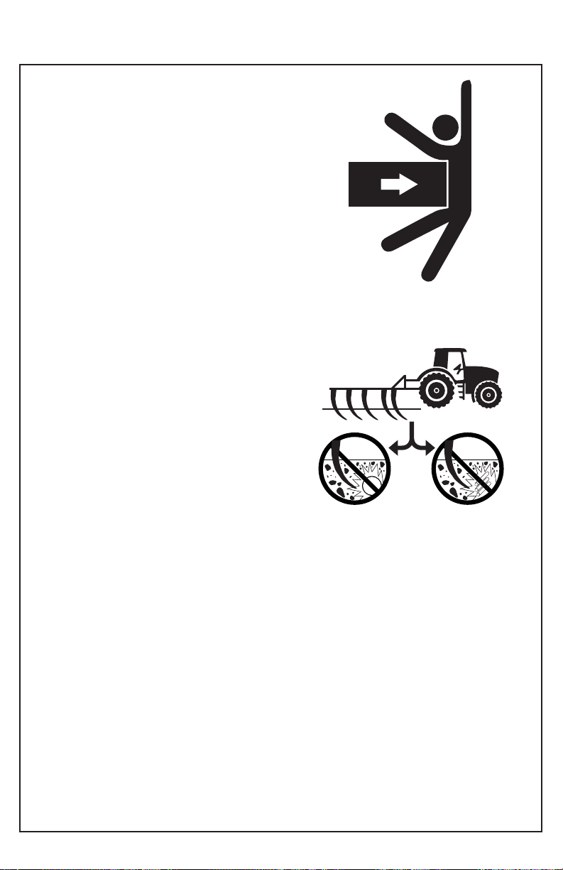
PASSENGERS ARE NOT ALLOWED IN THE
MACHINE
Only allow the operator on the machine.
Riders on machine are subject to injury such as
being struck by foreign objects and being thrown off
of the machine. Riders also obstruct the operators
view resulting in the machine being operated in an
unsafe manner.
BE PREPARED IN CASE OF EMERGENCY
Due to the flammable nature of many substances,
there should be a fire extinguisher within reach of
the operator.
Have on hand a first-aid kit for minor cuts and
scratches.
Keep the local emergency numbers near you.
WEAR APPROPIATE CLOTHING
Avoid wearing loose fitting clothing, use proper
safety equipment according to the type of work. The
safe operation of the equipment requires full
attention of the operator. Do not use headphones to
listen to the radio when traveling on roads.
USE SAFETY LIGHTS AND ACCESSORIES
Slow moving vehicles, tractors, trailed or suspend-
ed equipment can pose a risk when being transport-
ed or towed on a highway because they are difficult
to see, especially at night. Avoid injury or even
death that can result from a collision with other
vehicles.
It is recommended to use safety lights and accesso-
ries when driving on public roads. To improve
visibility, use all lights available on the tractor. The
additional installation of rotating warning lights is
recommended. Check that the signaling devices are
in good condition.
Replace lost or damaged safety attachments,
warning devices immediately.
08
WARNING WARNING

SAFE MAINTENANCE
Familiarize yourself with the maintenance
procedures before performing the work. The work
area must be clean and dry.
Do not carry out any greasing, repair or adjustment
work with the engine running.
Keep hands, feet and clothing away from moving
parts at all times. Put all controls in neutral to relieve
pressure. Lower all equipment to the ground. Stop
the engine. Remove the ignition key and wait for the
engine to cool.
Carefully support all machine parts being lifted for
maintenance work.
All components must be in good condition and
correctly installed. Repair damage immediately.
Replace any worn or broken parts. Keep all
machine components clean of grease, oil and
accumulated dirt.
CORRECT USE OF SEAT BELTS
Do not use a seat belt when working with a machine
that is not equipped with a rollover protector.
Transport the Subsoiler at a maximum of 10 mph.
Reduce speed when traveling over rough terrain.
Always drive at a speed that allows you to have
adequate steering and brake control.
09
SAFETY RULES
SAFETY WHEN OPERATING UNDERGROUND
Never ride or allow others to ride on the Subsoiler.
Move anyone away from the shanks when the
equipment is in operation.
Never stand in the way of the shanks when servic-
ing, as this could cause an accident.
Always lower the Subsoiler to the ground when not
in use.
Install front counterweights for optimum tractor
stability.
AVOID OBSTRUCTING ELECTRICAL, GAS OR
WATER LINES
Contact local government companies to determine
the location of electric, gas or water lines.
10
SAFETY RULES

TRACTOR PREPARATION
REQUIRED POWER
For recommended tractor power refer to the
specifications table in the specifications section.
(page 06).
REAR COUNTERWEIGHTS
When additional weight is required or instead of
liquid weight, cast iron counterweights can be
bolted to the rear tires.
Use rear counterweights to stabilize the tractor on
uneven terrain or hillsides, and to eliminate exces-
sive tire slippage. Counterweights should not be
added to the point of completely eliminating
skidding.
Tractor tires should be inflated to the pressure
recommended in your operator's manual.
FRONT COUNTERWEIGHTS
Add weight, if necessary, to the front of the tractor
for stability.
To improve tractor handling, remove front weights
when they are not needed.
Refer to the tractor operator's manual for adding
front weight.
Observe rear wheel tracks. When the tractor is
operating at optimum load, the ground between the
tire treads should be broken or sectioned (A).
If too much counterweight has been added, the
track marks will be crisp and clear (B).
If too little counterweight has been added, the track
marks will be almost blurred (C). Refer to the tractor
operator's manual.
11
OPERATION
ABC

12
SUBSOILER HITCHING TO TRACTOR
CAUTION: To avoid personal injury or machine
damage when an implement is hitched, place the
tractor transmission in the park position and check
for interference along the hitch.
Do not stand between the tractor and implement.
The sides of the tractor and implement are the only
access for connecting and disconnecting the hitch
points.
Slowly back the tractor into the Subsoiler, making
sure that the hitch points are aligned.
2. Place the transmission in park position.
3. Shut off the tractor engine.
4. Remove the pins from the Subsoiler side and
center hitches.
5. Align the tractor lift arms with the side hitches and
install the bolts.
6. Hitch the third point arm to the hitch plates and
install the bolt.
7. Start the tractor engine.
8. Slowly move the swing axle position control lever
to raise the implement. Check that there is no
difference.
9. Lower the implement to ground level, place the
transmission in park position and proceed to level
the Subsoiler by adjusting both lift arms to the same
length.
10. Finally adjust the third point arm (lengthen or
shorten) as required to achieve longitudinal leveling
of the Subsoiler.
OPERATION
TRANSPORTING SUBSOIL SAFELY
CAUTION: The Subsoiler should not be
transported at a speed greater than 10 mph, in
order to prevent accidents.
Higher speeds may result in loss of control of the
tractor if any of the outside rudders contact any
uneven ground surface.
Always drive at a speed that allows you to have
adequate steering and brake control.
When transporting the Subsoiler on a road or
highway at night or during the day, use lights and
devices for adequate warning to operators of other
vehicles. In this regard, check your local govern-
ment regulations for proper use. A machine that is
not properly illuminated could cause an accident,
which could result in serious injury or death to you
or others.
1. To obtain more lift from the Underlayment when
transporting, shorten the lift joints and center arm to
their minimum length, or hook the lift arms into the
lower holes in the hitch plates.
2. Place in transport position (upward) the rudders.

13
LATERAL SUBSOILER LEVELING
Lateral leveling is controlled by the tractor lift arms.
Make sure that the main body of the Subsoiler is
parallel to the ground so that all tiller arms rotate to
the same depth.
After the tiller arms have penetrated the ground and
you have set the working depth, stop the tractor and
stand behind the Subsoiler to confirm that the main
body is parallel to the ground.
If the main body is not parallel to the ground, raise
the implement and adjust the tractor hitch arms until
the Subsoiler is level.
LONGITUDINAL LEVELING OF THE SUBSOILER
Longitudinal leveling is controlled by the tractor's
center hitch arm.
To determine if the Subsoiler is level longitudinally,
observe the main body while working under load.
Make sure that all rudders are at the same level.
It is more efficient to work the Subsoiler when all
shanks are level.
If the main body is not level longitudinally raise the
Subsoiler and adjust it by lengthening or shortening
the third point arm.
OPERATION
14
LUBRICATION
CAUTION: Do not clean, lubricate or adjust the
machine when in motion.
IMPORTANT: The recommended periods are based
on normal operating conditions. In severe or
non-normal conditions, more frequent lubrication will
be necessary.
IMPORTANT: Clean the grease fittings before using
the grease gun. Replace any missing or broken grease
fittings immediately.
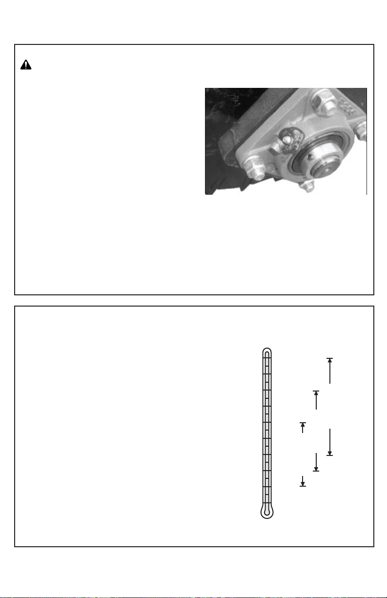
Lubricate the lump braker roller bearings before each
day's work. Apply grease until it comes out of the
gasket. Rotate the roller 2 or 3 times.
This process will extend the life of the bearings.
CORRECT USE OF SEAT BELTS
Do not use a seat belt when working with a machine
that is not equipped with a rollover protector.
Transport the Subsoiler at a maximum of 10 mph.
Reduce speed when traveling over rough terrain.
Always drive at a speed that allows you to have
adequate steering and brake control.
GREASE
Choose the most suitable type of grease according to
the NLGI consistency and the temperatures that may
occur in the interval until the next grease change.
You can use greases that meet the following standard:
NLGI consistency classification GC-LB.
Alternative and synthetic lubricants
Conditions in certain geographical areas may require
the use of special lubricants or lubrication techniques
not listed in the operator's manual.
Some lubricants may not be available in the area. In
this case, consult your distributor, who will provide you
with the most up-to-date information and
recommendations.
Lubricant Storage
Your equipment can operate at maximum efficiency
only if you use clean lubricant.
Use clean containers to handle all lubricants and store
them in an area protected from dust and moisture.
MAINTENANCE
50°C
40°C
30°C
20°C
10°C
0°C
-10°C
-20°C
-30°C
-40°C
122°C
104°C
86°C
68°C
50°C
32°C
14°C
-4°C
-22°C
-40°C
NLGI Number 0
NLGI Number 1
NLGI Number 2
15
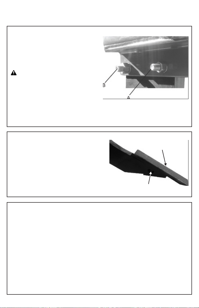
MAINTENANCE
B
A
FUSIBLE SCREW
The SVH-1 Subsoiler tiller is equipped with a fusible
safety screw (A).
This bolt will break if the tiller accidentally runs into
rocks, logs, roots, etc.
This protects the Subsoil and the tractor from possible
serious damage.
CAUTION: To avoid accidents, do not attempt to
remove a broken fusible link if the tiller is in a horizontal
position (tip up). With extreme caution, place the tiller
in the vertical (normal) position before replacing the
fusible safety plug.
IMPORTANT: The fusible safety bolt (A) must be
replaced with a grade 5 fusible safety bolt, do not use
any other hardness grade. After replacing the fusible
safety bolt, retighten the rudder bolt (B) according to
the bolt tightening specifications table on page 36.
REPLACEMENT OF THE TIPS
The replaceable scarifier tip (A) on the shanks (Shoe)
allows you to replace it with a new one when a tip has
been damaged, broken or worn.
To replace a tip, drive the pinch pin (B) out from
between the tip and the rudder with a 10 mm (3/8") pin
punch. Do not use a tapered punch.
Remove the damaged tip and install a new tip on the
chisel. Place the pinch bolt through the new tip and
shank.
KEEP THE SUBSOILER AVAILABLE
Thoroughly clean the Subsoiler before storing it.
Protect shanks and scarifying tips from corrosion by
applying a light coat of oil or grease.
Apply a good anti-corrosive when storing the Suboiler
for the next season.
After storage: Clean accumulated dust from moving
parts to prevent abrasion and excessive wear.
Inspect the Subsoiler thoroughly. Check for loose parts
and adjust if necessary.
This manual suits for next models
2
Table of contents
Other Bison Farm Equipment manuals

Popular Farm Equipment manuals by other brands

GREAT PLAINS
GREAT PLAINS Yield-Pro 3P3025AH manual

Art's-Way Manufacturing
Art's-Way Manufacturing 7165 Operator's manual

Guide Gear
Guide Gear 702141 quick start guide

Kongskilde
Kongskilde 2800 SERIES Assembly instructions

Backyard Discovery
Backyard Discovery Marco Series manual

dosatron
dosatron DosaCart Assembly instructions

Vicon
Vicon Andex 844 Assembly instructions

Degelman
Degelman STRAWMASTER PRO Series quick start guide

Topcon
Topcon CropSpec AGA5408 Operator's manual

Art's-Way Manufacturing
Art's-Way Manufacturing 6812 quick start guide

SaMASZ
SaMASZ KW 141 Operator's manual

GREAT PLAINS
GREAT PLAINS Terra Max HT1100-20 Operator's manual


