Exar XRA1403IL24-F User manual

1
REV. 1.0.0 XRA1403/1405 EVALUATION BOARD USER’S MANUAL
INTRODUCTION
This user’s manual is for the XRA1403/1405 16-bit evaluation board. Table 1 shows the different devices and
packages that the evaluation board supports. This user’s manual will describe the hardware setup required to
operate the different packages.
1.0 QUICK START
To verify communication with the GPIO expander, the following steps are recommended:
1.1 Connect external +5V power supply to J8 pin 1
1.2 Connect J12 pin 13 and 14 to ground of external power supply
1.3 Connect to MCU SPI interface for:
SPI clock (SCK_SCL signal at J5 pin11)
SO (SO_SPI signal at J5 pin17)
SI (SI_SPI signal at J5 pin21)
CS# (CS#_SPI signal at J5 pin19)
1.4 From the MCU, write the following registers:
GCR1 = 0x00
GCR2 = 0x00
If the LEDs turn on, the communication with the GPIO expander is successful.
To disable connection to LEDs, remove jumpers on J28, J29, J30 and J31. Connect to external inputs or
outputs at J3 and J4.
2.0 HARDWARE SETUP
2.1 Packages description
The evaluation board supports all 4 packages of the XRA1403 and XRA1405. The ordering part number,
package and location on the board is shown below in Table 1. Table 2 lists the evaluation board ordering part
numbers.
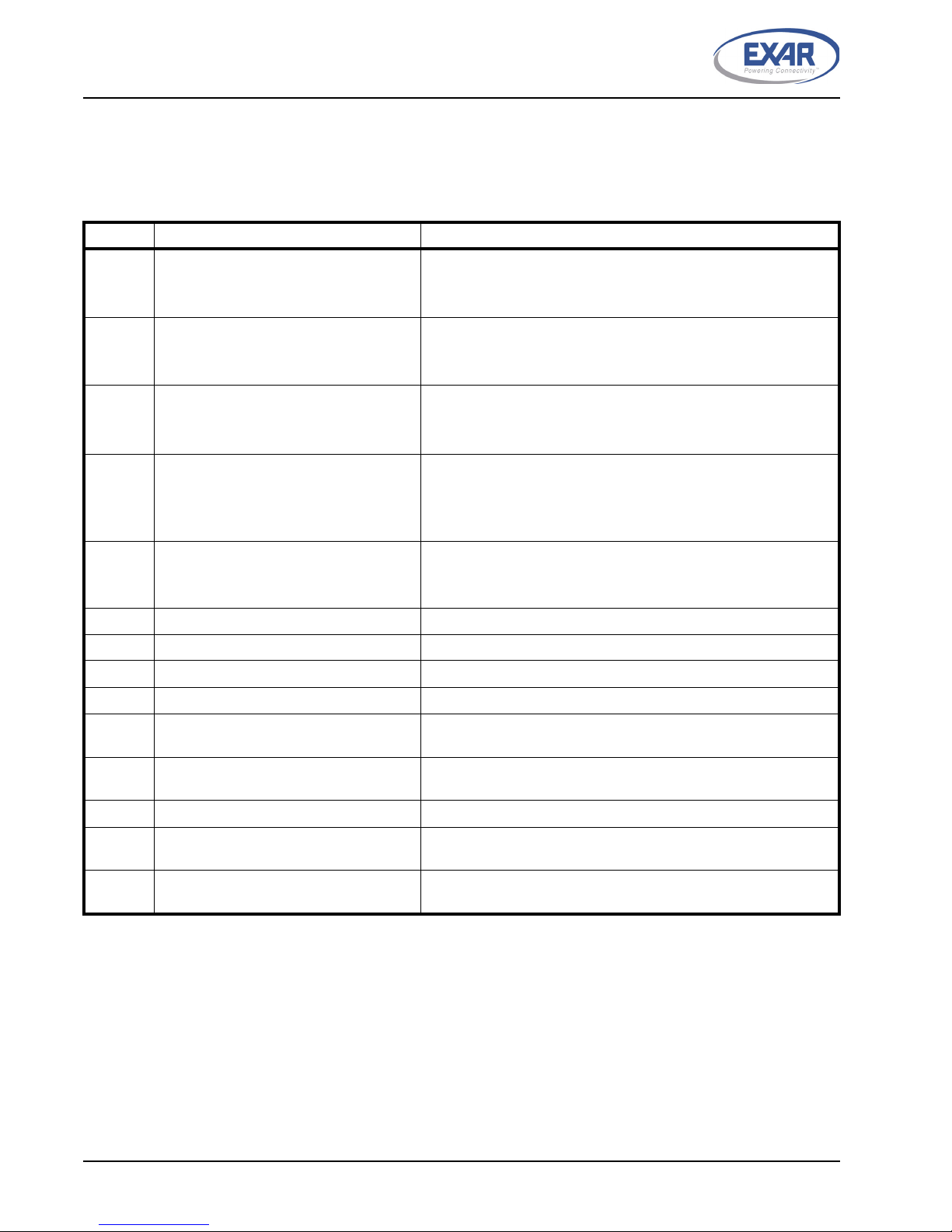
TABLE 1: PACKAGE LIST
ORDERING PART NUMBER PACKAGE LOCATION
XRA1403IL24-F 24-pin QFN U4
XRA1403IG24-F 24-pin TSSOP U5
XRA1405IL24-F 24-pin QFN U4
XRA1405IG24-F 24-pin TSSOP U5
TABLE 2: EVALUATION BOARD ORDERING PART NUMBERS
PART NUMBER
XRA1403IL24-0B-EB
XRA1403IG24-0B-EB
XRA1405IL24-0B-EB
XRA1405IG24-0B-EB
2
XRA1403/1405 EVALUATION BOARD USER’S MANUAL REV. 1.0.0
2.2 Jumper Settings
2.2.1 Common Jumpers
The following jumpers apply to all the 4 packages of XRA1403 and XRA1405:
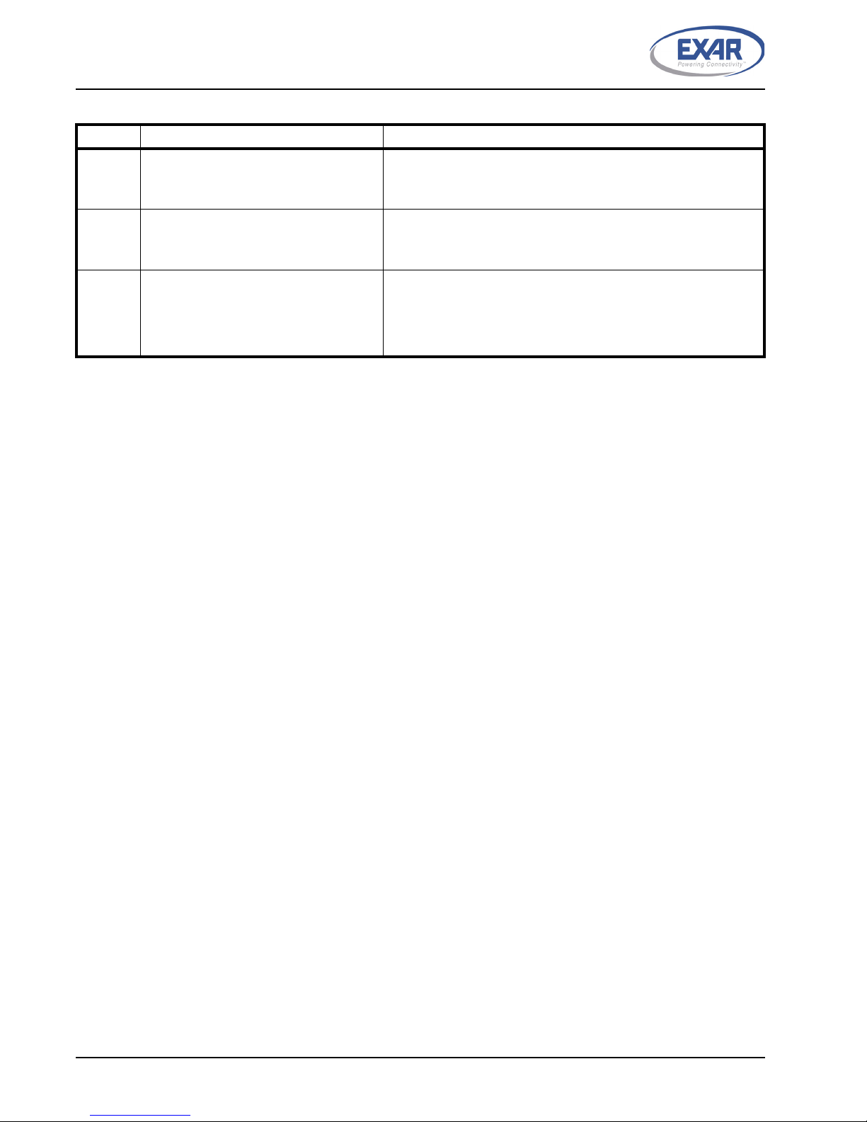
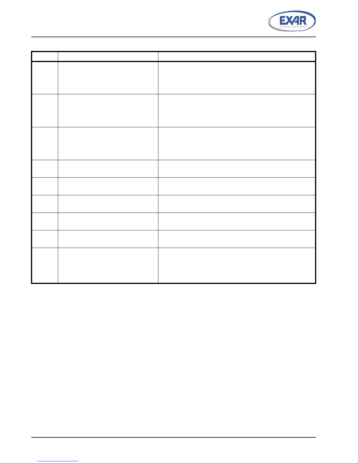
TABLE 3: COMMON JUMPER SETTINGS
JUMPERS FUNCTIONS COMMENTS
J8 Selects the supply voltage to generate
the +1.8V power supply for the board
1&2 selects +5V (default, Pin 1 -- Test point for external +5V)
2&3 selects +P
NOTE: Not installed. Trace between 1 & 2
J9 Selects the supply voltage to generate
the +2.5V power supply for the board
1&2 selects +5V (default)
2&3 selects +P
NOTE: Not installed. Trace between 1 & 2
J13 Selects the supply voltage to generate
the +3.3V power supply for the board
1&2 selects +5V (default)
2&3 selects +P
NOTE: Not installed. Trace between 1 & 2
J10 Selects the supply voltage for +VDDP Used only for the XRA1405
Jumper in 1&2 selects +3.3V
Jumper in 3&4 selects +2.5V
Jumper in 5&6 selects +1.8V
J11 Selects the supply voltage for +VDD Jumper in 1&2 selects +3.3V (default)
Jumper in 3&4 selects +2.5V
Jumper in 5&6 selects +1.8V
J12 Not used for XRA140x Installed but not used
J14 Not used for XRA140x Installed but not used
J6 Not used Installed but not used
J27 LEDs NOTE: Not installed. Pin 2 is connected to GND
J3 Header for testing GPIO[15:8] of both
TSSOP and QFN package
Installed. Connect to external input/output.
J4 Header for testing GPIO[7:0] of both
TSSOP and QFN package
Installed. Connect to external input/output. Remove jumpers on
J28, J29, J30 and J31 after test.
J2 Header for internal test Not installed
J5 Header for XRA1403 and XRA1405 sig-
nals and spare signals
Installed. Connect SPI signals from this header to MCU.
J7 Header for UART signals and spare sig-
nals
Not installed. Some GPIO signals and spare signals are accessi-
ble at this header

3
REV. 1.0.0 XRA1403/1405 EVALUATION BOARD USER’S MANUAL
2.2.2 XRA1403IL24-F
The following jumpers apply to the XRA1403IL24-F:
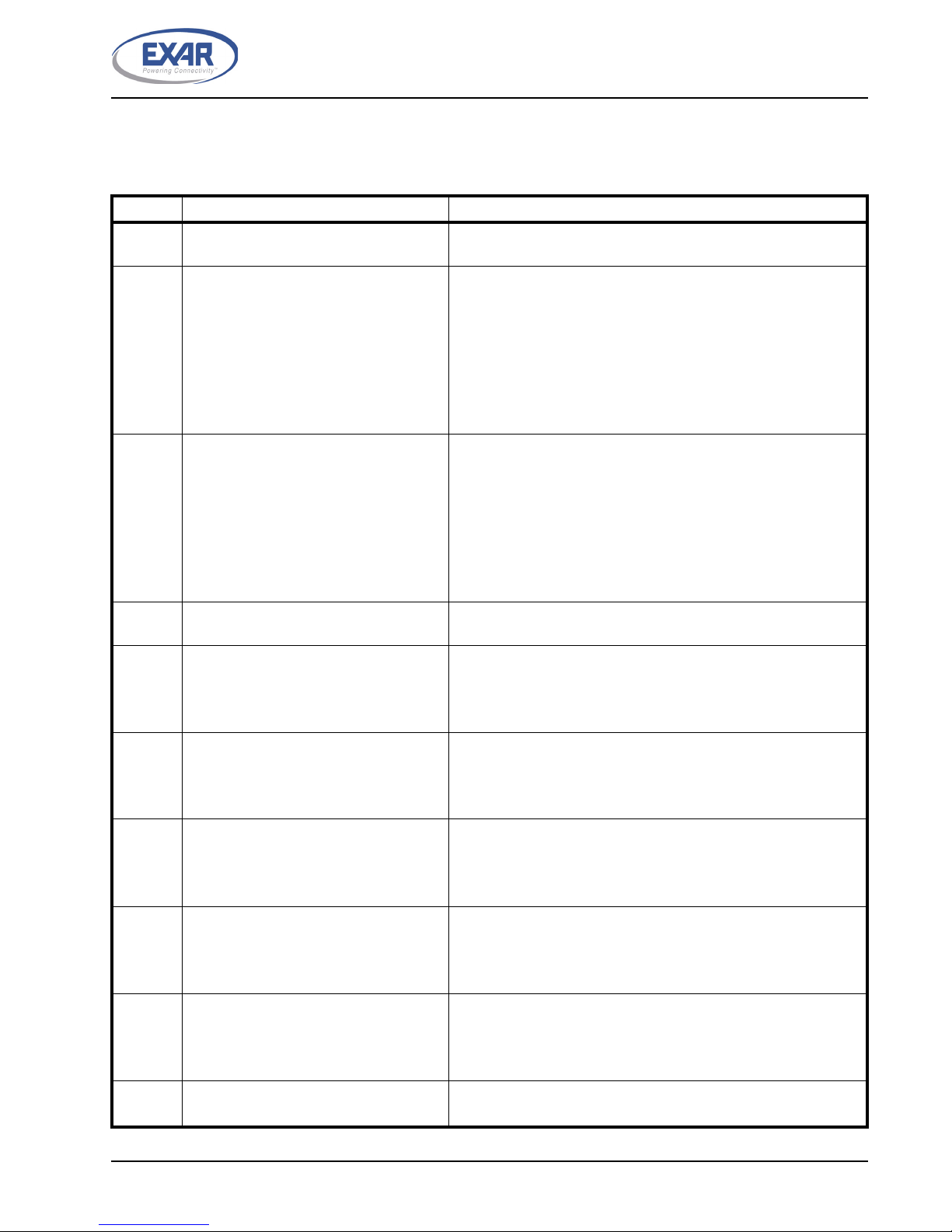
TABLE 4: JUMPER SETTINGS FOR XRA1403IL24-F
JUMPERS FUNCTIONS COMMENTS
J28 Header for connecting GPIO[7:0] signals
of QFN package
Jumper in pin 1 & J29 pin1 connects GPIO0 to LED
Jumper in pin 2 & J29 pin 3 connects GPIO1 to LED
Jumper in pin 3 & J29 pin 5 connects GPIO2 to LED
Jumper in pin 4 & J29 pin 7 connects GPIO3 to LED
Jumper in pin 5 & J29 pin 9 connects GPIO4 to LED
Jumper in pin 6 & J29 pin 11 connects GPIO5 to LED
Jumper in pin 7 & J29 pin 13 connects GPIO6 to LED
Jumper in pin 8 & J29 pin 15 connects GPIO7 to LED
J29 Header for connecting GPIO[7:0] signals
of TSSOP package to LEDs
1&2 connects GPIO0 to LED - 0 ohm resistor on board
3&4 connects GPIO1 to LED - 0 ohm resistor on board
5&6 connects GPIO2 to LED - 0 ohm resistor on board
7&8 connects GPIO3 to LED - 0 ohm resistor on board
9&10 connects GPIO4 to LED - 0 ohm resistor on board
11&12 connects GPIO5 to LED - 0 ohm resistor on board
13&14 connects GPIO6 to LED - 0 ohm resistor on board
15&16 connects GPIO7 to LED - 0 ohm resistor on board
J30 Header for connecting GPIO[15:8] signals
of TSSOP package to LEDs
1&2 connects GPIO8 to LED - 0 ohm resistor on board
3&4 connects GPIO9 to LED - 0 ohm resistor on board
5&6 connects GPIO10 to LED - 0 ohm resistor on board
7&8 connects GPIO11 to LED - 0 ohm resistor on board
9&10 connects GPIO12 to LED - 0 ohm resistor on board
11&12 connects GPIO13 to LED - 0 ohm resistor on board
13&14 connects GPIO14 to LED - 0 ohm resistor on board
15&16 connects GPIO15 to LED - 0 ohm resistor on board
J31 Header for connecting GPIO[15:8] signals
of QFN package
Jumper in pin 1 & J30 pin 1 connects GPIO8 to LED
Jumper in pin 2 & J30 pin 3 connects GPIO9 to LED
Jumper in pin 3 & J30 pin 5 connects GPIO10 to LED
Jumper in pin 4 & J30 pin 7 connects GPIO11 to LED
Jumper in pin 5 & J30 pin 9 connects GPIO12 to LED
Jumper in pin 6 & J30 pin 11 connects GPIO13 to LED
Jumper in pin 7 & J30 pin 13 connects GPIO14 to LED
Jumper in pin 8 & J30 pin 15 connects GPIO15 to LED
J81 Selects the supply voltage for +VDD for
24-pin QFN packages
Jumper in 2&4 selects +VDD (default)
Jumper in 1&3 selects +VDD
Jumper in 3&5 selects +VDD
J82 Selects the corresponding signal for pin
18 of 24-pin QFN package
NOTE: Use J87 pin 2 & 3
J83 Selects the corresponding signal for pin
23 of 24-pin QFN package
Jumper in 2&4 selects SI signal (default)
Jumper in 1&3 selects A1 signal
Jumper in 3&5 selects A1 signal
J84 Selects the corresponding signal for pin
24 of 24-pin QFN package
Jumper in 2&4 selects RESET# signal (default)
Jumper in 1&3 selects A2 signal
Jumper in 3&5 selects RESET# signal

4
XRA1403/1405 EVALUATION BOARD USER’S MANUAL REV. 1.0.0
J85 Selects the corresponding signal for pin
20 of 24-pin QFN package
Jumper in 2&4 selects SO signal (default)
Jumper in 1&3 selects SDA signal
Jumper in 3&5 selects SDA signal
J86 Selects the supply voltage for +VDDP for
24-pin QFN packages
Installed but not used for XRA1403IL24-F
Jumper in 1&2 selects +VDDP
Jumper in 2&3 selects +VDDP
J87 Selects the corresponding signal for pin
18 of 24-pin QFN package
Jumper in 2&3 selects CS# signal (default)
Jumper in 1&2 selects A0 signal
J88 Selects the corresponding signal for pin
23 of 24-pin QFN package
Installed but not used for XRA1403IL24-F
Jumper in 1&2 selects +VDD signal
Jumper in 2&3 selects +VDD signal
J89 Selects the corresponding signal for pin
24 of 24-pin QFN package
Installed but not used for XRA1403IL24-F
Jumper in 1&2 selects RESET# signal
Jumper in 2&3 selects SI signal
J90 Selects the corresponding signal for pin
20 of 24-pin QFN package
Installed but not used for XRA1403IL24-F
Jumper in 1&2 selects SDA signal
Jumper in 2&3 selects SO signal
J71, J72,
J73, J74,
J75, J76,
J77, J78,
J79, J80
Not used for XRA1403IL24-F Not installed.
TABLE 4: JUMPER SETTINGS FOR XRA1403IL24-F
JUMPERS FUNCTIONS COMMENTS

5
REV. 1.0.0 XRA1403/1405 EVALUATION BOARD USER’S MANUAL
2.2.3 XRA1403IG24-F
The following jumpers apply to the XR1403IG24-F:
TABLE 5: JUMPER SETTINGS FOR XRA1403IG24-F
JUMPERS FUNCTIONS COMMENTS
J28 Header for connecting GPIO[7:0] signals
of QFN package
Installed but not used
J29 Header for connecting GPIO[7:0] signals
of TSSOP package to LEDs
Jumper in 1&2 connects GPIO0 to LED
Jumper in 3&4 connects GPIO1 to LED
Jumper in 5&6 connects GPIO2 to LED
Jumper in 7&8 connects GPIO3 to LED
Jumper in 9&10 connects GPIO4 to LED
Jumper in 11&12 connects GPIO5 to LED
Jumper in 13&14 connects GPIO6 to LED
Jumper in 15&16 connects GPIO7 to LED
J30 Header for connecting GPIO[15:8] signals
of TSSOP package to LEDs
Jumper in 1&2 connects GPIO8 to LED
Jumper in 3&4 connects GPIO9 to LED
Jumper in 5&6 connects GPIO10 to LED
Jumper in 7&8 connects GPIO11 to LED
Jumper in 9&10 connects GPIO12 to LED
Jumper in 11&12 connects GPIO13 to LED
Jumper in 13&14 connects GPIO14 to LED
Jumper in 15&16 connects GPIO15 to LED
J31 Header for connecting GPIO[15:8] signals
of QFN package
Installed but not used
J71 Selects the supply voltage for +VDD for
24-pin TSSOP packages
Jumper in 2&4 selects +VDD (default)
Jumper in 1&3 selects +VDD
Jumper in 3&5 selects +VDD
J72 Selects the corresponding signal for pin
21 of 24-pin TSSOP package
NOTE: Use J78 pin 2 & 3
J73 Selects the corresponding signal for pin 2
of 24-pin TSSOP package
Jumper in 2&4 selects SI signal (default)
Jumper in 1&3 selects A1 signal
Jumper in 3&5 selects A1 signal
J74 Selects the corresponding signal for pin 3
of 24-pin TSSOP package
Jumper in 2&4 selects RESET# signal (default)
Jumper in 1&3 selects A2 signal
Jumper in 3&5 selects RESET# signal
J75 Selects the corresponding signal for pin
23 of 24-pin TSSOP package
Jumper in 2&4 selects SO signal (default)
Jumper in 1&3 selects SDA signal
Jumper in 3&5 selects SDA signal
J76 Selects the supply voltage for +VDDP for
24-pin TSSOP packages
Installed but not used for XRA1403IG24-F
Jumper in 1&2 selects +VDDP
Jumper in 2&3 selects +VDDP
J77 Selects the corresponding signal for pin 2
of 24-pin TSSOP package
Installed but not used for XRA1403IG24-F
Jumper in 1&2 selects +VDD signal
Jumper in 2&3 selects +VDD signal
J78 Selects the corresponding signal for pin
21 of 24-pin TSSOP package
Jumper in 2&3 selects CS# signal (default)
Jumper in 1&2 selects A0 signal
6
XRA1403/1405 EVALUATION BOARD USER’S MANUAL REV. 1.0.0
J79 Selects the corresponding signal for pin 3
of 24-pin TSSOP package
Installed but not used for XRA1403IG24-F
Jumper in 1&2 selects RESET# signal
Jumper in 2&3 selects SI signal
J80 Selects the corresponding signal for pin
23 of 24-pin TSSOP package
Installed but not used for XRA1403IG24-F
Jumper in 1&2 selects SDA signal
Jumper in 2&3 selects SO signal
J81, J82,
J83, J84,
J85, J86,
J87, J88,
J89, J90
Not used for XRA1403IG24-F Not installed
TABLE 5: JUMPER SETTINGS FOR XRA1403IG24-F
JUMPERS FUNCTIONS COMMENTS

7
REV. 1.0.0 XRA1403/1405 EVALUATION BOARD USER’S MANUAL
2.2.4 XRA1405IL24-F
The following jumpers apply to the XRA1405IL24-F:
TABLE 6: JUMPER SETTINGS FOR XRA1405IL24-F
JUMPERS FUNCTIONS COMMENTS
J28 Header for connecting GPIO[7:0] signals
of QFN package
Jumper in pin 1 & J29 pin 1 connects GPIO0 to LED
Jumper in pin 2 & J29 pin 3 connects GPIO1 to LED
Jumper in pin 3 & J29 pin 5 connects GPIO2 to LED
Jumper in pin 4 & J29 pin 7 connects GPIO3 to LED
Jumper in pin 5 & J29 pin 9 connects GPIO4 to LED
Jumper in pin 6 & J29 pin 11 connects GPIO5 to LED
Jumper in pin 7 & J29 pin 13 connects GPIO6 to LED
Jumper in pin 8 & J29 pin 15 connects GPIO7 to LED
J29 Header for connecting GPIO[7:0] signals
of TSSOP package to LEDs
1&2 connects GPIO0 to LED - 0 ohm resistor on board
3&4 connects GPIO1 to LED - 0 ohm resistor on board
5&6 connects GPIO2 to LED - 0 ohm resistor on board
7&8 connects GPIO3 to LED - 0 ohm resistor on board
9&10 connects GPIO4 to LED - 0 ohm resistor on board
11&12 connects GPIO5 to LED - 0 ohm resistor on board
13&14 connects GPIO6 to LED - 0 ohm resistor on board
15&16 connects GPIO7 to LED - 0 ohm resistor on board
J30 Header for connecting GPIO[15:8] signals
of TSSOP package to LEDs
1&2 connects GPIO8 to LED - 0 ohm resistor on board
3&4 connects GPIO9 to LED - 0 ohm resistor on board
5&6 connects GPIO10 to LED - 0 ohm resistor on board
7&8 connects GPIO11 to LED - 0 ohm resistor on board
9&10 connects GPIO12 to LED - 0 ohm resistor on board
11&12 connects GPIO13 to LED - 0 ohm resistor on board
13&14 connects GPIO14 to LED - 0 ohm resistor on board
15&16 connects GPIO15 to LED - 0 ohm resistor on board
J31 Header for connecting GPIO[15:8] signals
of QFN package
Jumper in pin 1 & J30 pin 1 connects GPIO8 to LED
Jumper in pin 2 & J30 pin 3 connects GPIO9 to LED
Jumper in pin 3 & J30 pin 5 connects GPIO10 to LED
Jumper in pin 4 & J30 pin 7 connects GPIO11 to LED
Jumper in pin 5 & J30 pin 9 connects GPIO12 to LED
Jumper in pin 6 & J30 pin 11 connects GPIO13 to LED
Jumper in pin 7 & J30 pin 13 connects GPIO14 to LED
Jumper in pin 8 & J30 pin 15 connects GPIO15 to LED
J81 Selects the supply voltage for +VDD for
24-pin QFN packages
Installed but not used for XRA1405IL24-F
Jumper in 1&3 selects +VDD
Jumper in 3&5 selects +VDD
Jumper in 2&4 selects +VDD
J82 Selects the corresponding signal for pin
18 of 24-pin QFN package
Installed but not used for XRA1405IL24-F
Jumper in 1&3 selects A0 signal
Jumper in 3&5 selects A0 signal
Jumper in 2&4 selects CS# signal
8
XRA1403/1405 EVALUATION BOARD USER’S MANUAL REV. 1.0.0
J83 Selects the corresponding signal for pin
23 of 24-pin QFN package
Installed but not used for XRA1405IL24-F
Jumper in 1&3 selects A1 signal
Jumper in 3&5 selects A1 signal
Jumper in 2&4 selects SI signal
J84 Selects the corresponding signal for pin
24 of 24-pin QFN package
Installed but not used for XRA1405IL24-F
Jumper in 1&3 selects A2 signal
Jumper in 3&5 selects RESET# signal
Jumper in 2&4 selects RESET# signal
J85 Selects the corresponding signal for pin
20 of 24-pin QFN package
Installed but not used for XRA1405IL24-F
Jumper in 1&3 selects SDA signal
Jumper in 3&5 selects SDA signal
Jumper in 2&4 selects SO signal
J86 Selects the supply voltage for +VDDP for
24-pin QFN packages
Jumper in 2&3 selects +VDDP (default)
Jumper in 1&2 selects +VDDP
J87 Selects the corresponding signal for pin
18 of 24-pin QFN package
Jumper in 2&3 selects CS# signal (default)
Jumper in 1&2 selects A0 signal
J88 Selects the corresponding signal for pin
23 of 24-pin QFN package
Jumper in 2&3 selects +VDD signal (default)
Jumper in 1&2 selects +VDD signal
J89 Selects the corresponding signal for pin
24 of 24-pin QFN package
Jumper in 2&3 selects SI signal (default)
Jumper in 1&2 selects RESET# signal
J90 Selects the corresponding signal for pin
20 of 24-pin QFN package
Jumper in 2&3 selects SO signal (default)
Jumper in 1&2 selects SDA signal
J71, J72,
J73, J74,
J75, J76,
J77, J78,
J79, J80
Not used for XRA1405IL24-F Not installed.
TABLE 6: JUMPER SETTINGS FOR XRA1405IL24-F
JUMPERS FUNCTIONS COMMENTS
9
REV. 1.0.0 XRA1403/1405 EVALUATION BOARD USER’S MANUAL
2.2.5 XRA1405IG24-F
The following jumpers apply to the XR1405IG24-F:
TABLE 7: JUMPER SETTINGS FOR XRA1405IG24-F
JUMPERS FUNCTIONS COMMENTS
J28 Header for connecting GPIO[7:0] signals
of QFN package
Installed but not used
J29 Header for connecting GPIO[7:0] signals
of TSSOP package to LEDs
Jumper in 1&2 connects GPIO0 to LED
Jumper in 3&4 connects GPIO1 to LED
Jumper in 5&6 connects GPIO2 to LED
Jumper in 7&8 connects GPIO3 to LED
Jumper in 9&10 connects GPIO4 to LED
Jumper in 11&12 connects GPIO5 to LED
Jumper in 13&14 connects GPIO6 to LED
Jumper in 15&16 connects GPIO7 to LED
J30 Header for connecting GPIO[15:8] signals
of TSSOP package to LEDs
Jumper in 1&2 connects GPIO8 to LED
Jumper in 3&4 connects GPIO9 to LED
Jumper in 5&6 connects GPIO10 to LED
Jumper in 7&8 connects GPIO11 to LED
Jumper in 9&10 connects GPIO12 to LED
Jumper in 11&12 connects GPIO13 to LED
Jumper in 13&14 connects GPIO14 to LED
Jumper in 15&16 connects GPIO15 to LED
J31 Header for connecting GPIO[15:8] signals
of QFN package
Installed but not used
J71 Selects the supply voltage for +VDD for
24-pin TSSOP packages
Installed but not used for XRA1405IG24-F
Jumper in 1&3 selects +VDD
Jumper in 3&5 selects +VDD
Jumper in 2&4 selects +VDD
J72 Selects the corresponding signal for pin
21 of 24-pin TSSOP package
Installed but not used for XRA1405IG24-F
Jumper in 1&3 selects A0 signal
Jumper in 3&5 selects A0 signal
Jumper in 2&4 selects CS# signal
J73 Selects the corresponding signal for pin 2
of 24-pin TSSOP package
Installed but not used for XRA1405IG24-F
Jumper in 1&3 selects A1 signal
Jumper in 3&5 selects A1 signal
Jumper in 2&4 selects SI signal
J74 Selects the corresponding signal for pin 3
of 24-pin TSSOP package
Installed but not used for XRA1405IG24-F
Jumper in 1&3 selects A2 signal
Jumper in 3&5 selects RESET# signal
Jumper in 2&4 selects RESET# signal
J75 Selects the corresponding signal for pin
23 of 24-pin TSSOP package
Installed but not used for XRA1405IG24-F
Jumper in 1&3 selects SDA signal
Jumper in 3&5 selects SDA signal
Jumper in 2&4 selects SO signal
J76 Selects the supply voltage for +VDDP for
24-pin TSSOP packages
Jumper in 2&3 selects +VDDP (default)
Jumper in 1&2 selects +VDDP

10
NOTICE
EXAR Corporation reserves the right to make changes to the products contained in this publication in order to
improve design, performance or reliability. EXAR Corporation assumes no responsibility for the use of any
circuits described herein, conveys no license under any patent or other right, and makes no representation that
the circuits are free of patent infringement. Charts and schedules contained here in are only for illustration
purposes and may vary depending upon a user’s specific application. While the information in this publication
has been carefully checked; no responsibility, however, is assumed for inaccuracies.
EXAR Corporation does not recommend the use of any of its products in life support applications where the
failure or malfunction of the product can reasonably be expected to cause failure of the life support system or
to significantly affect its safety or effectiveness. Products are not authorized for use in such applications unless
EXAR Corporation receives, in writing, assurances to its satisfaction that: (a) the risk of injury or damage has
been minimized; (b) the user assumes all such risks; (c) potential liability of EXAR Corporation is adequately
protected under the circumstances.
Copyright 2011 EXAR Corporation
Datasheet October 2011.
Send your UART technical inquiry with technical details to hotline: uarttechsupport@exar.com.
Reproduction, in part or whole, without the prior written consent of EXAR Corporation is prohibited.
XRA1403/1405 EVALUATION BOARD USER’S MANUAL REV. 1.0.0
3.0 TECHNICAL SUPPORT
If there are any questions, please send an e-mail to uarttechsupport@exar.com.
J77 Selects the corresponding signal for pin 2
of 24-pin TSSOP package
Jumper in 2&3 selects +VDD signal (default)
Jumper in 1&2 selects +VDD signal
J78 Selects the corresponding signal for pin
21 of 24-pin TSSOP package
Jumper in 2&3 selects CS# signal (default)
Jumper in 1&2 selects A0 signal
J79 Selects the corresponding signal for pin 3
of 24-pin TSSOP package
Jumper in 2&3 selects SI signal (default)
Jumper in 1&2 selects RESET# signal
J80 Selects the corresponding signal for pin
23 of 24-pin TSSOP package
Jumper in 2&3 selects SO signal (default)
Jumper in 1&2 selects SDA signal
J81, J82,
J83, J84,
J85, J86,
J87, J88,
J89, J90
Not used for XRA1405IG24-F Not installed
TABLE 7: JUMPER SETTINGS FOR XRA1405IG24-F
JUMPERS FUNCTIONS COMMENTS
This manual suits for next models
7
Table of contents
Other Exar Motherboard manuals

Exar
Exar XRP7720EVB-DEMO-1 User manual

Exar
Exar XRP7664-65-74-75 User manual

Exar
Exar XR21B1424IV64-0A-EVB User manual

Exar
Exar XR22414-EVB User manual

Exar
Exar SP336E User manual

Exar
Exar XRP6141 User manual

Exar
Exar XRP7740EVB-HIC Operating and maintenance instructions

Exar
Exar Power XR Series User manual

Exar
Exar XRP6142 User manual

Exar
Exar XR20M1280 User manual


Popular Motherboard manuals by other brands


Linx Technologies
Linx Technologies LT Series user guide

Freescale Semiconductor
Freescale Semiconductor LS1043ARDB quick start

Honeywell
Honeywell DCP551 Mark ll user manual

IWILL
IWILL P4G Series user manual

Texas Instruments
Texas Instruments Jacinto 7 quick start guide

Gigabyte
Gigabyte GA-MA74GMT-S2 user manual


