Excelitas Technologies X-Cite mini+ User manual

X-Cite®mini+ User Guide
Applies to X-Cite mini Series Models:
XMPS
XMPL
XTMS
XTML
XT120Lm (X-Cite 120LEDmini)

2
X-Cite® mini+ User Guide
035-00587R rev. 5
X-Cite® mini+ User Guide
035-00587R rev. 5
Made in Canada
Excelitas Canada Inc. 2020
All rights reserved
No part of this publication may be reproduced, transmitted, transcribed, stored in a retrieval system or
translated into any language in any form by any means without the prior written consent of Excelitas
Canada Inc. Every effort has been made to ensure information in this manual is accurate; however,
information in this manual is subject to change without notice and does not represent a commitment on
the part of the authors.
Excelitas Canada Inc.
2260 Argentia Road
Mississauga ON L5N 6H7
CANADA
Trademarks
X-Cite®is a registered trademark of Excelitas Canada Inc. All rights reserved.
All other product names are trademarks of their respective owners.

3
X-Cite® mini+ User Guide
035-00587R rev. 5
Table of Contents
1Introduction ...............................................................................................................................5
2Safety.........................................................................................................................................6
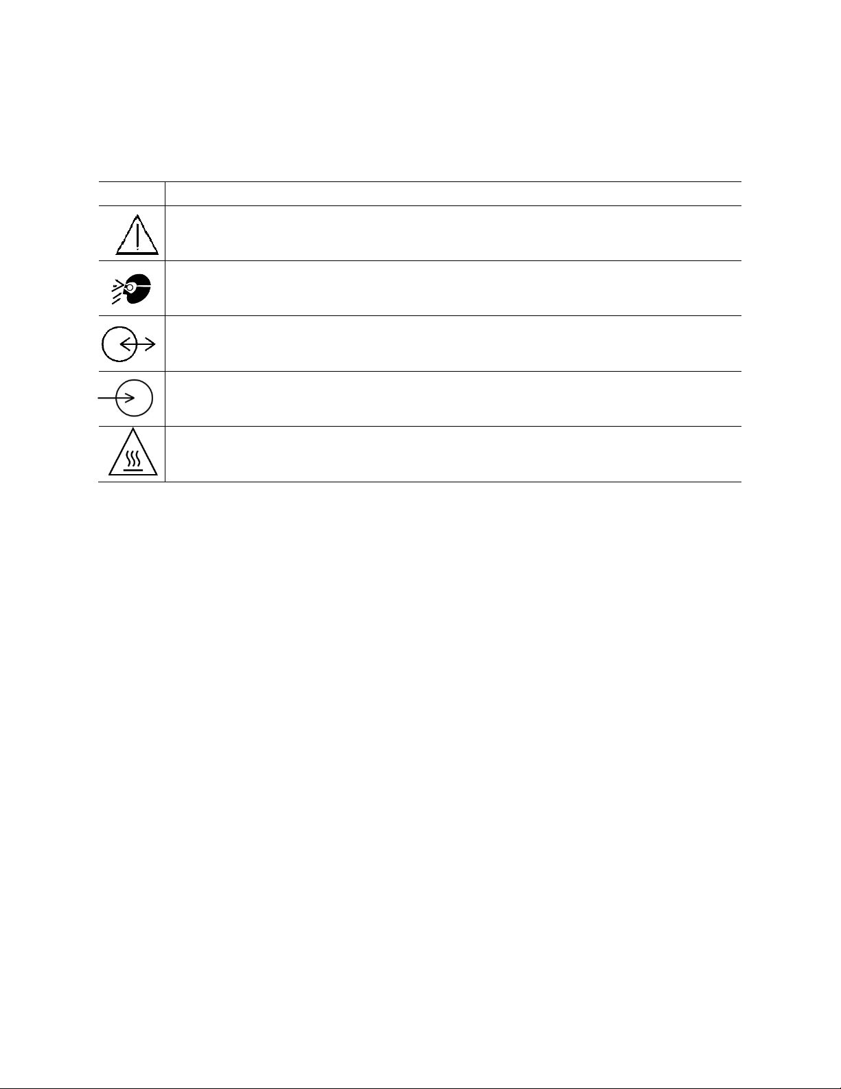
2.1 Glossary of Symbols ......................................................................................................................6
2.2 Safety Precautions ........................................................................................................................6
3Getting Started...........................................................................................................................8
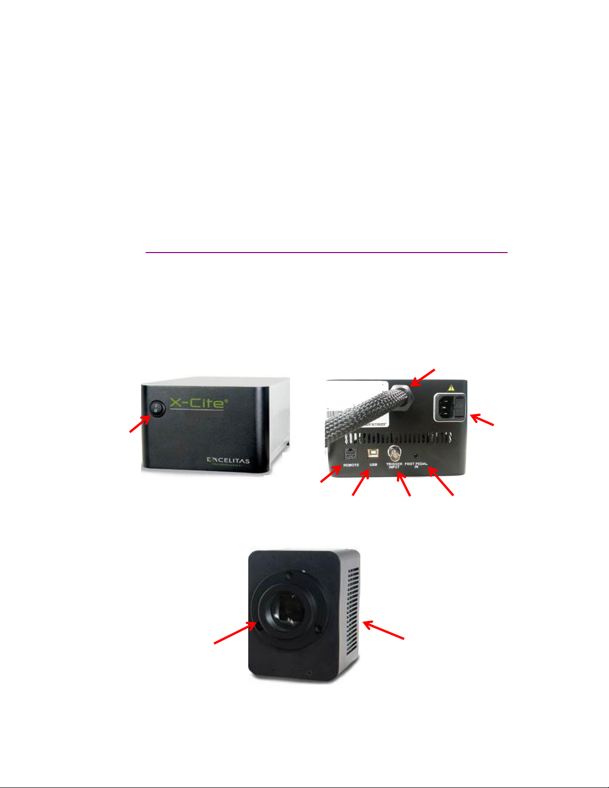
3.1 System Components .....................................................................................................................8
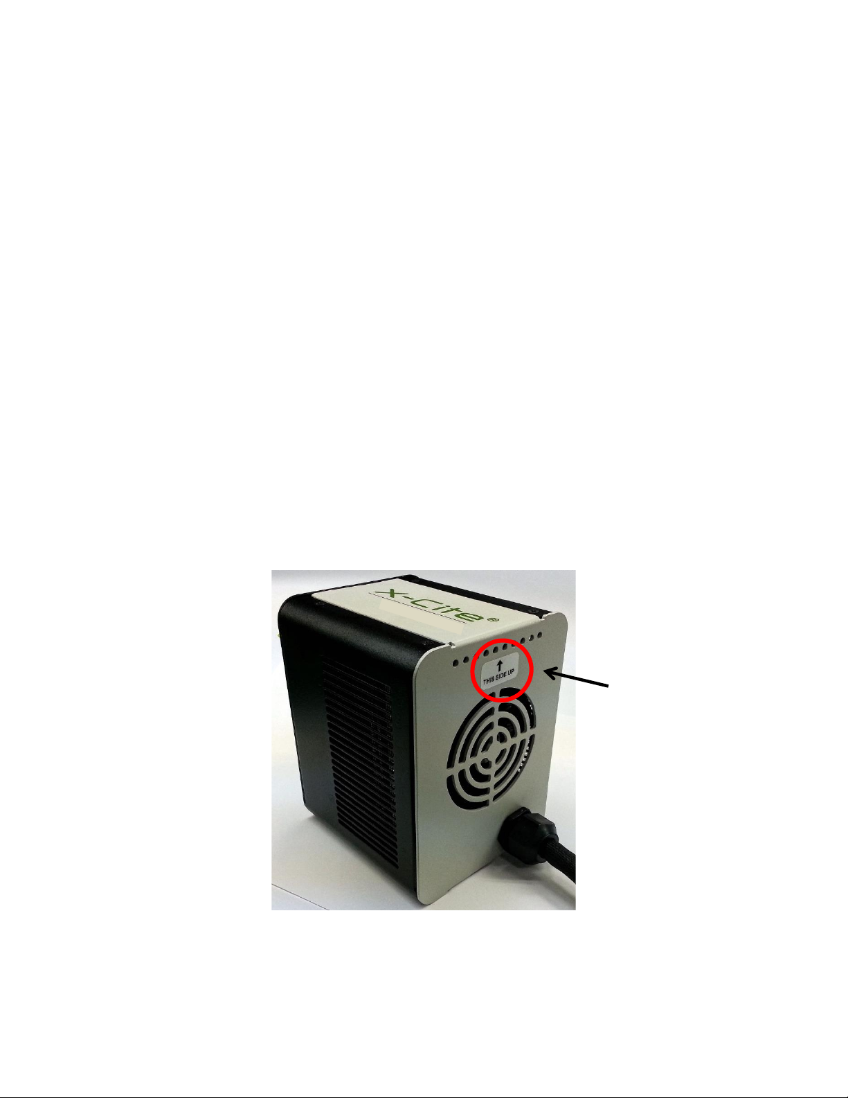
3.2 Installation/Set-up ........................................................................................................................9
4Operation –Manual Control .....................................................................................................12
4.1 The Basics....................................................................................................................................12
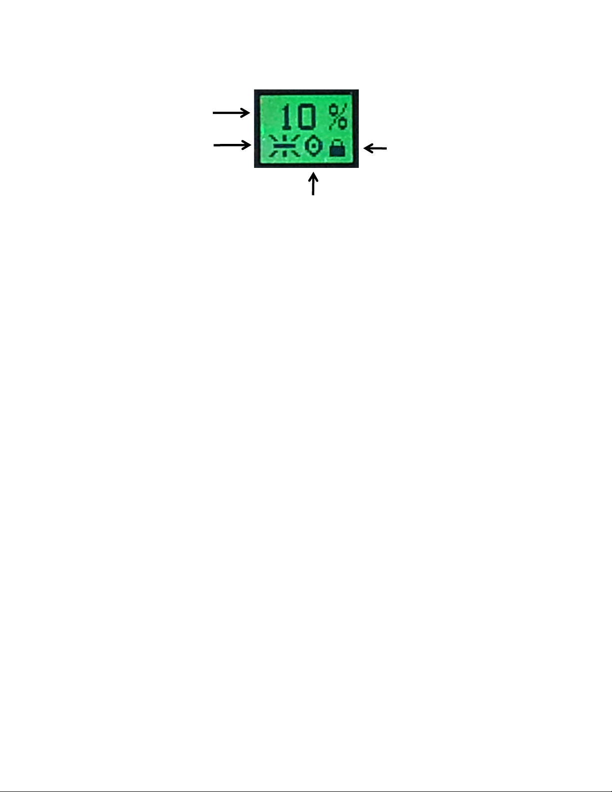
4.2 SpeedDIAL Home Screen.............................................................................................................13
4.3 SpeedDIAL Menu and Settings....................................................................................................13
4.3.1 SpeedDIAL Menu Structure.................................................................................................14
4.3.2 LCD Display Screen Brightness and Color Settings...........................................................14
4.3.3 Favo Favorite Intensity Setting.........................................................................................15
4.3.4 TTL TTL Mode Control.......................................................................................................15
4.3.5 UV UV Mode Control........................................................................................................16
4.3.6 Hand Display Screen Orientation.....................................................................................16
4.3.7 Srvc Service Data..............................................................................................................16
5Operation - External Control .....................................................................................................17
5.1 USB/RS-232 .................................................................................................................................17
5.1.1 Driver Installation (via internet)..........................................................................................17
5.1.2 Driver Installation (via ZIP file)............................................................................................18
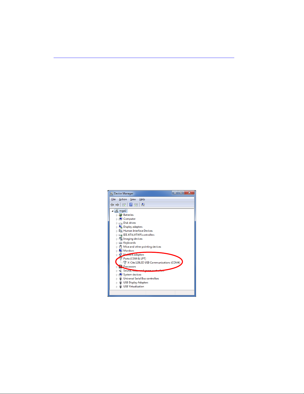
5.1.3 Verify Installation & Get COM Port Number.......................................................................18
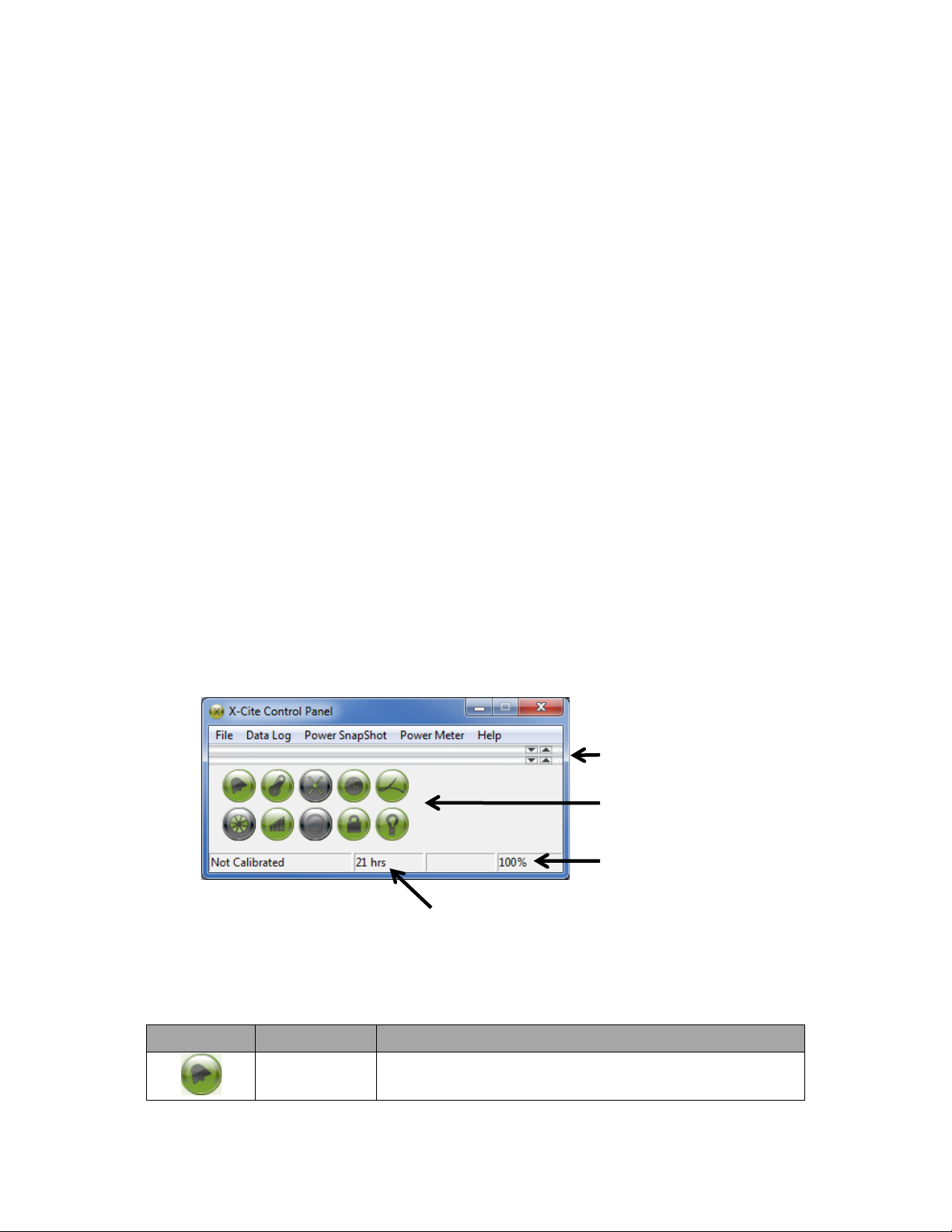
5.1.4 X-Cite® Control Panel / GUI installation..............................................................................18
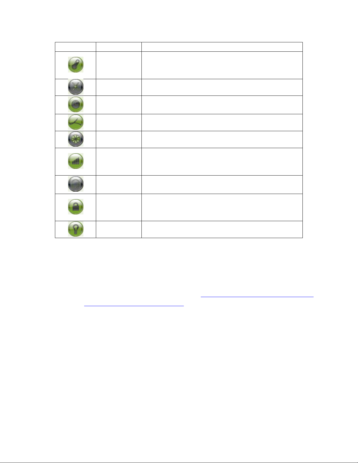
5.1.5 X-Cite Control Panel Tips for Use .....................................................................................19
5.1.6 Commercial Software Support............................................................................................ 20
5.1.7 Softw...........................................................................................20
5.2 TTL...............................................................................................................................................21
5.2.1 TTL Mode ............................................................................................................................21
5.2.2 TTL Mode Timeout..............................................................................................................21
5.2.3 TTL Timing Diagram.............................................................................................................21
5.2.4 TTL Signal and LED Status....................................................................................................22
5.2.5 TTL Input Specifications ......................................................................................................22
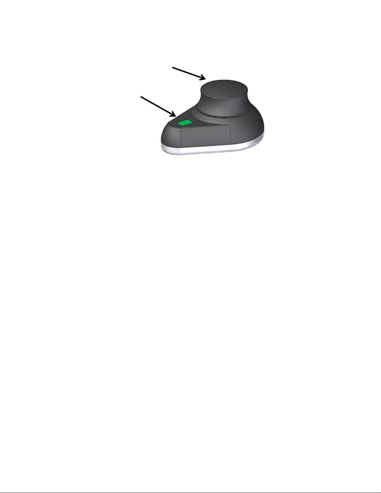
5.3 Foot Pedal Control (Optional).....................................................................................................22
6Troubleshooting .......................................................................................................................23
6.1 Error Messages............................................................................................................................23
6.2 Failure to Power Up ....................................................................................................................23
6.3 Low Illumination Intensity ..........................................................................................................25
6.4 Other Potential Symptoms & Questions.....................................................................................25
7Routine Care and Maintenance.................................................................................................26
7.1 General........................................................................................................................................26

4
X-Cite® mini+ User Guide
035-00587R rev. 5
7.2 Cleaning - Exterior Surfaces ........................................................................................................26
7.3 Cleaning - Optical Surfaces .........................................................................................................26
7.4 Thermal Management System....................................................................................................27
8Technical Specifications ............................................................................................................27
8.1 General........................................................................................................................................27
8.2 Electrical......................................................................................................................................27
8.3 Environmental Operating Conditions ......................................................................................28
8.4 Environmental Transport and Storage Conditions...................................................................28
8.5 Input/Output (I/O) Connections .................................................................................................28
8.6 Output Stability...........................................................................................................................28
9Regulatory................................................................................................................................29
9.1 Product Safety and Electromagnetic Compatibility....................................................................29
9.1.1 Optical Safety......................................................................................................................29
9.2 CE Marking ..................................................................................................................................30
9.3 FCC ..............................................................................................................................................30
9.4 WEEE Directive............................................................................................................................30
9.5 China RoHS..................................................................................................................................31
9.6 Australia - RCM ...........................................................................................................................31
10 Warranty & Repairs ..............................................................................................................32
10.1 Warranty Terms ..........................................................................................................................32
10.2 Returning equipment to Excelitas Technologies.........................................................................32
11 Contact Information..............................................................................................................33
11.1 General........................................................................................................................................33
11.2 Technical Support and Service....................................................................................................33
11.3 Accessories and Replacement Parts ...........................................................................................33
Table of Figures
Figure 1 miniCUBE Front and Rear Panels ................................................................................................... 8
Figure 2 LED Head ........................................................................................................................................ 8
Figure 3 SpeedDIAL ......................................................................................................................................9
Figure 4 Installing Microscope Flange on LED Head ..................................................................................10
11
Figure 6 SpeedDIAL Home Screen Icons
Figure 7 Device Manager, COM Port Listing18
Figure 8 X-Cite® Control Panel ...................................................................................................................19
Figure 9 Sequence of Events for TTL Mode Timeout (set to 4 hours) .......................................................21
Figure 10 Location and Removal of Fuse Tray in AC Receptacle ...............................................................24

5
X-Cite® mini+ User Guide
035-00587R rev. 5
1Introduction
The new X-Cite® mini+ provides LED illumination with no compromise. X-Cite® mini+ provides superior
optical power and exceptional field uniformity at the specimen level with the broadest spectrum of
fluorescence excitation through manual, PC and TTL control. With LEDs rated to 20,000 hours and no
lamps or modules to replace, X-Cite® mini+ offers sheer simplicity in its compact size and convenience to
researchers allowing them to focus on their experiments instead of equipment maintenance.
This product is intended for use in fluorescence microscopy illumination. It allows researchers the ability
to excite fluorescence in samples being studied and characterize their location or behavior.
Excelitas Technologies Corp. is a global technology leader focused on delivering innovative, customized
solutions to meet the lighting, detection and other high-performance technology needs of customers. X-
Cite®, formerly of Lumen Dynamics (which was acquired by Excelitas Technologies Corp. in November
2013) offers the Life Science and Analytical Instrumentation market a broad range of innovative lamp
and LED fluorescence illumination and measurement solutions.
Excelitas Technologies recommends reading this manual to discover all the features available in X-Cite®
mini+.
Thank you for choosing X-Cite®!

6
X-Cite® mini+ User Guide
035-00587R rev. 5
2Safety
2.1 Glossary of Symbols
Symbol
Meaning
CAUTION - Risk of danger: consult accompanying documents
WARNING Eye damage may result from directly viewing ultraviolet light. Protective eye
shielding and clothing must be used at all times.
Input/Output Signals
Input Signal
CAUTION Hot surface
2.2 Safety Precautions
Please observe the following safety precautions at all times during operation and maintenance of this
product. Failure to do so may result in personal injury or property damage.
1. UV emitted from this product. Avoid eye and skin exposure to unshielded product. Do not look
at operating lamp/LED. Eye injury may result.
2. Never look into the light emitting end of the LED head. The light could severely damage the
cornea and retina of the eye if the light is observed directly. Eye shielding must be used at all
times as well as clothing to protect exposed skin.
3. Always make sure the LED head is securely attached to the microscope prior to turning on
power to the unit. This will minimize the risk of exposure to the UV light.
4. To reduce the risk of fire or shock, always replace the fuses with the same type and rating.
5. Disconnecting of main supply source is done by putting the
and unplugging the power cord.
6. It is recommended that ONLY QUALIFIED TECHNICAL PERSONNEL perform any testing or repairs
described in this manual. Disconnect the AC power cord from the unit before opening the cover
of this unit. All cover screws must be replaced prior to applying power to the unit, or safety of
the unit will be impaired.

7
X-Cite® mini+ User Guide
035-00587R rev. 5
7. Monitoring the unit during manual operation
The level of UV and visible energy supplied by this product is sufficient to ignite flammable
substances. During manual operation, the unit must be attended at all times by a qualified
operator. The unit must not be left unattended while turned on. If an operator leaves the work
area of the unit, the power switch must be turned off.
8. Monitoring the unit during automated operation
The level of UV and visible energy supplied by this product is sufficient to ignite flammable
substances. Therefore, when the unit is operated unattended in an automated environment, an
alarm function must be provided by the user to indicate a malfunction in the associated
equipment used.
9. Should this X-Cite® unit be used in a manner not specified by Excelitas Technologies, the
protection provided by the equipment may be impaired.
10. This unit is designed for bench top use only! Always ensure that the unit is placed on a hard,
stable surface, ensuring that ventilation openings are not obstructed. Any obstruction of these
openings could result in a possible over-heating condition.
11. Any electronic equipment connected to this product must comply with the requirements of
EN/IEC 60950.
12. To clean the exterior of the unit, use a slightly dampened cloth and a simple water/ detergent
solution only. Avoid the optical surfaces and lenses. Cleaning of optics should only be attempted
by qualified personnel using appropriate fluids and lens paper.

8
X-Cite® mini+ User Guide
035-00587R rev. 5
3Getting Started
3.1 System Components
The X-Cite® mini+ system contains the following components:
1. LED Head and miniCUBE (permanently connected via 1.5m cable)
2. SpeedDIAL Manual Controller
3. Microscope Flange
4. Accessories Box, containing:
a. Quick Start Instruction Sheet (User Guide, Software/Driver downloads are available:
https://www.excelitas.com/product/x-cite-mini-compact-led-illumination-system)
b. Hex Tool, 3mm
c. USB Cable
d. Power Cord
e. Safety Precautions Booklet
If any components are missing or appear damaged, please contact Excelitas Technologies immediately.
Figure 1 miniCUBE Front and Rear Panels
Figure 2 LED Head

9
X-Cite® mini+ User Guide
035-00587R rev. 5
Figure 3 SpeedDIAL
3.2 Installation/Set-up
1. Unpack
a. Carefully unpack the unit and accessories from the shipping carton.
b. When removing the LED Head and miniCUBE from the carton, ensure that both
components are supported and there is always some slack in the cable. Excessive strain
on the cable may damage or weaken the connection.
c. Do not use the cable as a “handle”.

10
X-Cite® mini+ User Guide
035-00587R rev. 5
2. Install the Microscope Flange
a. Remove protective wrap from the Microscope Flange, being careful not to touch the
lens surfaces.
b. Remove protective cap from LED Head. Never power up the unit with this cap installed
–it can melt very quickly at high power settings and damage the unit.
c. Align the mounting holes on the Microscope Flange and the LED Head. Attach the
Microscope Flange using the Hex Tool and three (3) fasteners provided. The two (2)
dowel pins on the LED Head will allow you to install the Flange quickly and in the proper
position as required by your microscope.
Figure 4 Installing Microscope Flange on LED Head
3. Position the equipment
a. miniCUBE should be positioned to avoid sharp bends and strain on the cable.
b. The front panel of miniCUBE should be within reach to access the main power switch.
(During operation, all other functions are controlled via speedDIAL or USB interface.)
c. Air vents on both sides of miniCUBE should be clear of obstruction. Recommended
clearance is 20cm (8 inches) on all sides.

11
X-Cite® mini+ User Guide
035-00587R rev. 5
4. Connect LED Head to Microscope
a. Insert Microscope Flange portion of the LED Head into the light port on the microscope,
and secure it using the hardware provided on the microscope. (Refer to relevant
microscope user manual for complete instructions on mounting a standard epi-
fluorescence lamphouse.) General guidelines:
i. Carl Zeiss Tighten the hex fastener on the side of the light port with the 3mm
Hex Tool.
ii. Leica - Tighten the hex fastener on the side of the light port with the 3mm Hex
Tool .
iii. Nikon
fitting, hold the LED head firmly against the light port, and twist the collar to
lock the components together.
iv. Olympus - Tighten the hex fastener(s) with the 3mm Hex Tool. Depending on
the model, there may be one (1) fastener on the side, or two (2) fasteners
located at the 10:00 and 2:00 positions. Note for IX3-RFAL use: the epi-light
train aperture MUST be properly aligned before turning on X-Cite® mini+, or
heat damage may result - see procedure in Olympus manual for assistance.
b. Verify that the LED Head is oriented with the arrow label (rear side of the LED Head) is
pointing up (see Figure 5).
c. Verify that the LED Head is securely fastened by attempting to gently rock it from side to
side.
Figure 5 LED Head and Arrow in Correct Position

12
X-Cite® mini+ User Guide
035-00587R rev. 5
5. Connect speedDIAL to miniCUBE
a. Insert the mini DIN plug miniCUBE. Ensure the
arrow mark on the connector is on top and centered. Note: Never force the connector
this can damage the pins. If connector does not insert smoothly, stop and check for
bent pins.
b. Place speedDIAL next to the microscope, or another easily accessible location.
6. Connect USB (if using)
a. miniCUBE.
b.
c. Note: For best performance, use the supplied USB cable or one of equivalent quality
and length. Using a longer USB cable than the one supplied may result in intermittent
communication errors.
7. Connect AC Power
a. Connect female end to AC port on rear of the miniCUBE.
b. Connect male end to a properly grounded electrical outlet.
c. For safe operation, use only the power cord supplied or one with an equivalent rating.
4Operation –Manual Control
4.1 The Basics
1. Start the unit
a. Flip the rocker switch on the front of miniCUBE to turn X-Cite® mini+ on.
b. The system will have a brief initialization period (approximately 10 seconds). The
speedDIAL X-Cite
c.
d. Note: If speedDIAL will be used for manual control, it must be connected before turning
system on. SpeedDIAL can be damaged if it is plugged into, or unplugged from, the
system while it is powered on.
2. Illuminate a specimen
a. Click the dial (shutter button) on speedDIAL to turn on/off the excitation light.
3. Adjust intensity
a. Turn the dial to adjust intensity - clockwise to increase, counter-clockwise to decrease.
b. The dial is speed sensitive turning slowly will allow adjustments in smaller increments,
turning quickly will increase the step sizes.
NOTE: Power cycling of the main unit (off and then on) requires a minimum of 10 seconds of off
time. Failure to wait at least 10 seconds before restarting the unit after powering down may
cause memory and USB communication errors.

13
X-Cite® mini+ User Guide
035-00587R rev. 5
4.2 SpeedDIAL Home Screen
Figure 6 SpeedDIAL Home Screen Icons
4.3 SpeedDIAL Menu and Settings
In addition to the intuitive intensity adjustment and illumination ON/OFF control, speedDIAL has several
advanced settings and control options.
To access the main menu, press and hold the dial for one (1) second.
To navigate the menus, turn the dial to scroll through the options. An arrowhead will indicate
the currently selected menu option; click the dial to make a selection.
To adjust settings, turn the dial. To exit the setting adjustment, click the dial.
To exit menu system at any time, press and hold the dial for one (1) second.
Note: Setting changes will take effect immediately after selection. However, for the first five (5)
minutes, the new settings are stored in a temporary memory location. If X-Cite® mini+ is powered down
during this time, settings will revert back to their previous values. To ensure that new settings will be
remembered, wait at least five (5) minutes before powering down the unit.

14
X-Cite® mini+ User Guide
035-00587R rev. 5
4.3.1 SpeedDIAL Menu Structure
4.3.2 LCD –Display Screen Brightness and Color Settings
In the LCD sub menu, the backlight on the display screen can be turned on/off, set to a different
brightness level, or set to a different color.
a. LCDoption from main menu.
b. To adjust LCD display backlight time out:
i. D options, which are: Off and 1 thru
999 seconds in 1 second increments. Offwill turn off the backlight timer (i.e.
backlight will always be on).
ii. Click dial to save selection and return to LCDmenu.
c. To adjust LCD brightness:
i. SBrigthe desired level is
reached. To turn backlight off, set level to 0%.
ii. Click dial to save selection and return to LCDmenu.
d. To change LCD color:
LCD
Dim
Brig
Color
Exit
Favo
Int
Enbl
Spd
Exit
TTL
Enbl
Time
Exit
UV
Hand
Srvc
Hour
SN
Tmp1
Tmp2
S/W1
S/W2
Exit
Exit

15
X-Cite® mini+ User Guide
035-00587R rev. 5
i. the options until desired color is on
LCD.
ii. Click dial to save selection and return to LCDmenu.
e. the main menu, or press and hold dial to return to the home
screen.
4.3.3 Favo –Favorite Intensity Setting
In the FAVO sub menu, a favorite, commonly used intensity setting can be saved. When this
mode is enabled, the intensity level will instantly jump to this setting with a double-click of the
dial. A second double-click will toggle back to the previous intensity level.
a.
b. To set/change the favorite intensity:
i. the desired level is
reached.
ii. Click dial to save selection
iii. TIP: Scrolling through % settings in this menu will not actually change the output
in real time, even if LED is on. The favorite intensity should be determined
before entering this menu.
c. To enable/disable favorite intensity mode:
i. the desired setting.
(i.e. double-click speedDIAL = Favorite setting)
O (i.e. double-click speedDIAL = do nothing)
ii. Click
d. To adjust the delay between clicks -click:
i. the desired delay setting.
the
ii. Click
iii. TIP: If double-clicking results in the light being turned OFF instead of going to
favorite intensity, increase the delay setting.
iv. Note: Setting long delay times will result in a longer response time for regular
ON/OFF control with speedDIAL (the system must wait to see if the single-click
turns into a double-click). Response times for TTL, USB or foot pedal on/off
control will not be affected.
4.3.4 TTL –TTL Mode Control
In the TTL menu, TTL mode can be enabled for experiments that require rapid LED ON/OFF
control. For further information on TTL mode, refer to the External Control, TTL section 5.2.
NOTE: TTL mode MUST be enabled for the system to respond to a TTL signal.
a.
b. To enable/disable TTL mode:
i.
ii. Scroll to the desired setting, Onto enable TTL or Offto disable TTL.

16
X-Cite® mini+ User Guide
035-00587R rev. 5
iii. Click dial to save selection and return to TTLmenu.
c. To define the TTL timeout setting:
i.
ii. Scroll through the time out options, which are: Never and 4 to 24 hours in half
hour increments. (i.e. the cooling
system and driver will always be active when TTL mode is enabled).
iii. Click dial to save selection and return to TTLmenu.
4.3.5 UV –UV Mode Control
**Models XMPS/XMPL and XTMS/XTML only.**
In this menu, the UV LED can be
experiment, i.e. it is not intended to be a fast-switching system.
To disable/enable UV:
a.
b.
c. Click dial to return to the main menu.
*Note that while the UV setting can be changed while the LEDs are turned ON, the change to
the UV LED will not take effect until the next time the LEDs are turned on. To avoid confusion, it
recommended to change settings with the LEDs turned off.
4.3.6 Hand –Display Screen Orientation
In this menu, the LCD orientation can be rotated 180°. This allows operators to use speedDIAL
on the left or right side of the microscope without blocking the view of the display with their
hand.
d. from main menu.
e. Turn dial to Handote that the
screen will flip while adjusting this setting.
f. Click dial to save selection and return to the main menu.
4.3.7 Srvc –Service Data
In the Service menu, information specific to each X-Cite® mini+ unit can be found. This includes
total hours accumulated on the LED, unit serial number, temperatures measured at specific
locations in the unit, and embedded software versions for miniCUBE and speedDIAL. Excelitas
Tech Support personnel may request some or all of this information during a support call.
a. option from main menu.
b. To obtain the hours:
i. Select .
ii. LED hours of will be shown in one (1) hour increments from 0 to 999
hours. Due to space limitations on the LCD, when 1000 hours are logged, the
hourswill increase to 100 hours

17
X-Cite® mini+ User Guide
035-00587R rev. 5
). The precise hour-by-hour data will
continue to be available via USB communication.
iii. Click dial to return to Srvcmenu.
c. To obtain the unit serial number:
i. Select option.
ii. Serial number of the unit will be shown.
iii. Click dial to return to Srvcmenu.
d. To obtain current system temperatures:
i. Select as required.
ii. Temperature will be shown in degrees Celsius.
iii. Click dial to return to Srvcmenu.
e. To obtain the embedded software version numbers:
i. Select the 1 menu items.
ii. The software version numbers will be shown in the format X.X.X.
iii. Click dial to return to Srvcmenu.
5Operation - External Control
5.1 USB/RS-232
A virtual COM port driver must be installed to enable Windows communication via the USB port. For
computers running Windows which are connected to the internet, the driver will install automatically.
For manual installation, the driver is available as a software download from the Excelitas website. Note
that administrator privileges may be required to install drivers on your computer, in which case you may
need to contact your IT department for assistance.
5.1.1 Driver Installation (via internet)
For these instructions: internet is required, Windows 7 prompts are listed
a. Ensure X-Cite® mini+ is powered off.
b. Ensure X-Cite® mini+ is connected to the computer with the USB cable.
c. Ensure computer is connected to internet.
d. Power on X-Cite® mini+.
e. Driver installation will begin automatically. A dialogue box will confirm installation has
started.
i. If the dialogue box reports that Driver installation was not successful, click on
Get Details.
ii. Click on option to Change Settings to Automatically search Windows for
drivers. Confirm Yes, do this automatically, and save changes.
f. A second dialogue box will confirm successful installation and provide a COM port
number. Note the COM port number for use in other software applications.

18
X-Cite® mini+ User Guide
035-00587R rev. 5
5.1.2 Driver Installation (via ZIP file)
For these instructions, download the driver ZIP file from the Excelitas website:
https://www.excelitas.com/product/x-cite-mini-compact-led-illumination-system
a. Ensure X-Cite® mini+ is powered off.
b. Ensure X-Cite® mini+ is connected to the computer with the USB cable.
c. Prepare the driver files by extracting and saving the files into a folder on the desktop (or
another easily accessible location).
d. Power on X-Cite® mini+.
e. No to search Windows update for
the software. Click Next to continue.
f. Select Install from a list or specific location (Advanced) to locate the driver and click
Next. Select Include this location in the search and browse to the location on your hard
drive where unzipped files were saved in step c. Click Next.
g. Wait for installation to complete. Click Finish.
5.1.3 Verify Installation & Get COM Port Number
a. O
b. X-Cite 120LED will be listed under COM .
c. Note the COM port number for use in other software applications.
Figure 7 Device Manager, COM Port Listing
5.1.4 X-Cite® Control Panel / GUI installation
For these instructions: ZIP file is available as a software download from the Excelitas website.

19
X-Cite® mini+ User Guide
035-00587R rev. 5
a. Uninstall any previous versions of X-Cite® Control Panel/GUI. (Previous versions
released under the EXFO name will not be automatically replaced by versions 1.1.0 or
later, and may cause confusion.)
b. Prepare the driver files (if not already done in previous section) by extracting and saving
the files into a folder on desktop (or another easily accessible location).
c. To begin installation, go to unzipped files from step b, double-click on setup.exe or
setup
d. Setup Wizard will open. Follow prompts and click Close when Wizard is finished.
e. To find GUI, go to: Start, All Programs, Lumen Dynamics, X-Cite Control Panel. Click to
start/open GUI, or click-and-drag to copy a shortcut to desktop or Quick Launch toolbar.
5.1.5 X-Cite Control Panel –Tips for Use
a. X-Cite Control Panel is available as a download from the Excelitas website. This tool
provides an interface for controlling the X-Cite® mini+ via PC and general testing of the
communication port.
b. Note that X-Cite® Control Panel is designed to function with multiple X-Cite® devices,
and not all icons and features can be used with all devices. See the icon table below to
determine which icons are relevant to control of X-Cite® mini+.
c. Icon color code:
i. Green icons mean status is OK and/or the function is engaged
ii.
iii. Red icons mean there is an alarm condition
iv. Grey icons mean a feature is not engaged, and/or not available
v. If icons are ALL grey, X-Cite® mini+ is not connected and/or turned off
Figure 8 X-Cite Control Panel
ICON
NAME
DESCRIPTION
Alarm
Green = All OK
Red = Alarm on

20
X-Cite® mini+ User Guide
035-00587R rev. 5
Click will clear alarm, unless unsafe to ignore
Temperature
Indicates system temperature status
Yellow = warning, LED temp above normal
Red = LED off, temp is too high
Calibration
Not applicable for X-Cite® mini+
LED Hours
Indicates hours logged on LED
Green = <20K hours, yellow = >20K hours, red = >40K hours
Light Guide
Not applicable for X-Cite® mini+
Shutter
Click to turn LED on/off
Intensity
Left mouse click = increase by 1% increment.
Right mouse click = decrease by 1% increment.
Left double click = opens dialog box type in value
Closed-Loop
Feedback
Not applicable for X-Cite® mini+
Lock/unlock
Lock/unlock speedDIAL control
Green = speedDIAL is locked
Grey = speedDIAL is unlocked
Lamp
Not applicable for X-Cite® mini+
5.1.6 Commercial Software Support
a. X-Cite® mini+ can be controlled through many commercially available packages. Where
X-Cite® mini+ specific control may not be available, basic functionality can be achieved
using X-Cite® 120PC or X-Cite® exacte hardware drivers. For an updated list of software
packages that support X-Cite® products, see https://www.excelitas.com/product/x-cite-
mini-compact-led-illumination-system
b. For commercial software packages, if requested specify the serial port parameters as:
19,200 baud, no parity, 8 data bits and 1 stop bit.
c. When controlling X-Cite® mini+, some commercial software packages may block manual
input from speedDIAL. The lock icon will appear on the speedDIAL display in these
cases.
5.1.7 Software Developer’s Kit (SDK)
The command list for X-Cite® mini+ is available by request. To obtain the latest update, please
contact Excelitas Technologies.
Table of contents
Other Excelitas Technologies Lighting Equipment manuals

Excelitas Technologies
Excelitas Technologies X-Cite mini+ Series User manual

Excelitas Technologies
Excelitas Technologies X-Cite 110LED User manual

Excelitas Technologies
Excelitas Technologies XLED1 User manual

Excelitas Technologies
Excelitas Technologies X-Cite TURBO User manual

Excelitas Technologies
Excelitas Technologies X-Cite 200DC User manual

Excelitas Technologies
Excelitas Technologies OmniCure V3 User manual

Excelitas Technologies
Excelitas Technologies X-Cite 120LEDBoost User manual