When there is flammable accessory on the flash unit, do not keep the
modeling lamp on for a long time. It is recommended to cool it down
for one minute after 10 minutes' working.
4. When in NON OFF mode, long press the < > Button for 2 seconds to switch
on the function that the modeling is off when triggering the flash. Now the LCD
panel shows ( ). Long press the < > Button again to exit this mode.
3. When PROP is displayed, short press the < > Button can back to <OFF>
mode.
GR/CH Button
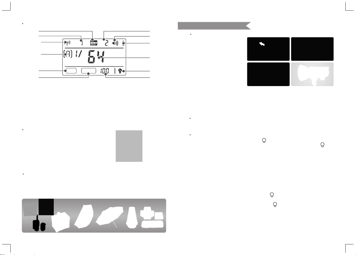
Power Output Control
Select dial decides different power output, satisfying light requirements in
different environment. The power is adjustable freely from 1/64 to 1/1 which will
be accordingly shown on the LCD display. "OFF" on the display indicates that the
flash triggering function is turned off. Press the test button to discharge power
when the flash output is adjusted from high to low.
Test Button
To fire the flash without taking a picture, press the test button. It can also help
adjust the flash brightness when combined with the select dial. Press the SET
button and turn on the flash to view its version.
Sync Triggering
The sync cord jack is a Φ3.5mm plug.
Insert a trigger plug here and the flash will
be fired synchronously with the camera
shutter. Synchronously press the S1/S2
button and BUZZ button to recover factory
settings.
Short press the GR/CH button can adjust the built-in wireless group. When the
group indicator on the LCD panel is blinking, turn the select dial to change. And
long press the GR/CH button can adjust the built-in wireless channel. When the
channel indicator on the LCD panel is blinking, turn the select dial to change.
Slave Trigger Model
Three slave triggering models are available and can be set by pressing<S1/S2>
slave model button.
◆No optical control: S1 or S2 is not displayed on the LCD panel, indicating the
slave triggering function is shut down.
◆Optic S2 Secondary Unit Setting: Press <S1/S2> button so that this flash can
also function as an optic S2 secondary flash with optic sensor in M manual flash
mode. This is useful when cameras have pre-flash function. With this function,
the flash will ignore a single “preflash” from the main flash and will only fire in
response to the second, actual flash from the main unit.
◆Optic S1 Secondary Unit Setting: In M manual flash mode, press <S1/S2>
button so that this flash can function as an optic S1 secondary flash with optic
sensor. With this function, the flash will fire synchronously when the main flash
fires, the same effect as that by the use of radio triggers. This helps create
multiple lighting effects.
Buzz Function
The BUZZ button is used for deciding whether there is sound reminder for ready
flash after recharging. When the buzz indicator is on the LCD panel, the buzz
function is working; when it is disappear, the buzz function is not working. A “BI”
sound will be heard when it’s fully charged.
Wireless Button
Press the < > Button can turn on/off the built-in wireless transmission. If there
are no wireless and channel indicators displayed on the LCD panel, the built-in
wireless transmission is off. On the contrary, the built-in wireless transmission is
on.When turning the flash on, press the BUZZ button and S1/S2 button
simultaneously, and factory setting can be restored.
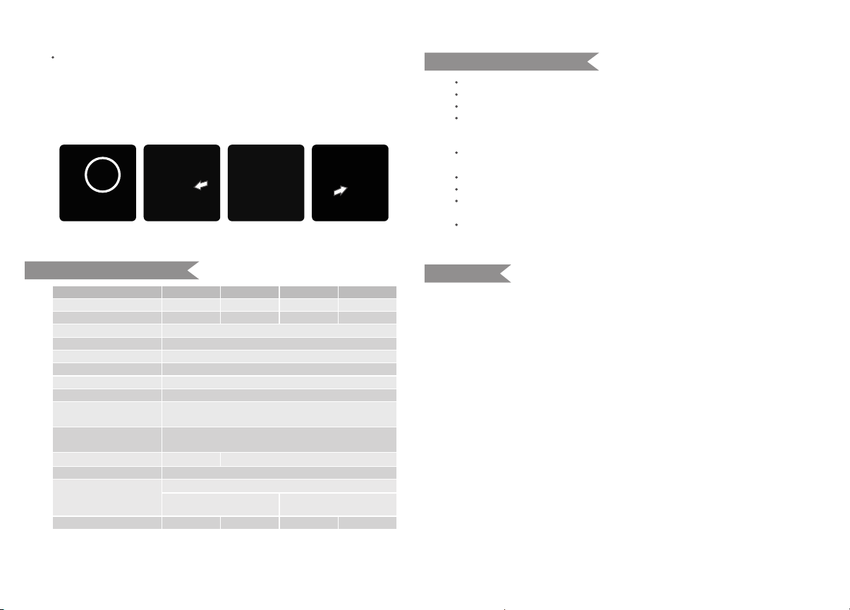
E0
E3
Alarm
sounds
Alarm Display
The temperature sensor is not connected.
Discharged capacitance and voltage > rating +10%
BIBI, ringing per 0.5 second. Press SET button to stop alarming.
C.Fn
F1
F2
Wireless ID setting Set it to OF or choose any figure from 01 to 99.
When setting to OF, wireless ID will be turned off.
And 01 to 99 means the wireless ID is turned on.
Flash power display It can be displayed in 1/P or P.P.
- 16 -- 15 -