Excell EX-2005C User manual

EXCELL PRECISION CO., LTD
.
EX-2005C
Check-weigh
Indicator
User Manual
©
EXCELL PRECISION CO., LTD. 2011. All rights reserved worldwide.
The information contained herein is the property of EXCELL PRECISION CO., LTD. and is
supplied without liability for errors or omissions. No part may be reproduced or used except
as authorised by contract or other written permission. The copyright and the foregoing
restriction on reproduction and use extend to all media in which the information may be
embodied.

EX-2005C ZSME300000116
1
EXCELL PRECISION CO., LTD
.
TABLE OF CONTENTS
SAFETY PRECAUTION ...............................................................................................................2
CHAPTER 1 PANELS AND SPECIFICATION.............................................................................3
1-1 Front Panel.........................................................................................................................3
1-2 Rear Panel..........................................................................................................................4
1-3 Keypad Description...........................................................................................................5
1-4 A/D Conversion..................................................................................................................6
1-5 Power Supply.....................................................................................................................6
1-6 Dimensions (mm) ..............................................................................................................7
CHAPTER 2 GENERAL FUNCTION............................................................................................8
2-1 Function Setting Procedures ...........................................................................................8
2-2 Function Setting................................................................................................................9
CHAPTER 3 CALIBRATION DESCRIPTION.............................................................................12
3-1 Load Cell Connection......................................................................................................12
3-2 Parameter Setting And Calibration Flowchart ..............................................................13
3-3 Specification Calibration ................................................................................................15
3-4 General Calibration .........................................................................................................17
3-5 Error Messages ...............................................................................................................18
CHAPTER 4 INTERFACE DESCRIPTION.................................................................................19
CHAPTER 5 MAINTENANCE ....................................................................................................26
5-1 Restore All Parameters To Default Factory Values.......................................................26
5-2 Test Mode.........................................................................................................................27
5-2-1 7-Segment Display Testing......................................................................................28
5-2-2 Keypad And Calibration SW Testing.......................................................................28
5-2-3 Display A/D Internal Value Display..........................................................................28
5-2-4 RS-232 Serial Loop Back Testing............................................................................28
5-2-5 EEPROM Memory Testing........................................................................................28
5-2-6 IFC Factory Testing (reserved)................................................................................28
5-2-7 RELAY_IO Interface Card Testing............................................................................28
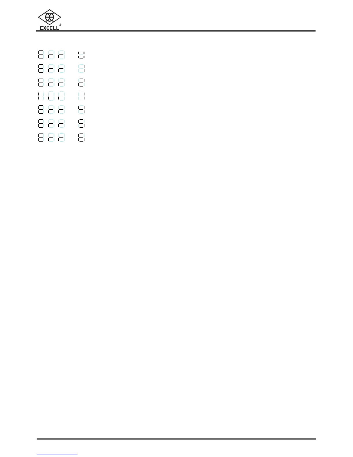
APPENDIX 7-SEGMENT DISPLAY CHARACTERS .................................................................29

EX-2005C ZSME300000116
2
EXCELL PRECISION CO., LTD
.
!
SAFETY PRECAUTION
When the indicator is installed, connect an earth bonding conductor from FG
to the earth connection marked “ ”.
Disconnect the mains power supply before opening the rear panel for whatever.
To install the optional interface cards, it is necessary to disconnect the mains
power supply and fit a yellow/green earth bonding cable to the rear panel.
(Fixed with another two earth bonding cables)
Before turning the power on ensure the supply voltage is within the
acceptable range, AC 85 ~ 265 V.
The operating ambient temperature range is -10 ~ +40 °C (+14 ~ +104 °F).
Thank you for purchasing EXCELL Check-weigh
Indicator. To guide you to use our product correctly,
please read the user manual carefully to avoid
mis-operating this product.

EX-2005C ZSME300000116
3
EXCELL PRECISION CO., LTD
.
CHAPTER 1 PANELS AND SPECIFICATION
1-1 Front Panel
Display
6 digits, bright red, 7 segment LED display, character height 16mm (0.63”).
Indication icons “◄”
HI
◄
:
Weight over High Limit indication
OK
◄
:
Weight qualified indication
LO
◄
:
Weight below Lo Limit indication
RUN
◄
:
Check-weighing in operation indication
Weight units
Weighing Units “kg”,“g.
Weight Unit
Display Area
Indication
Weight Unit

EX-2005C ZSME300000116
4
EXCELL PRECISION CO., LTD
.
1-2 Rear Panel
Terminal Block Calibration Switch
Calibration Switch set to the left is “OFF” and to the right is “ON”
13 Way Terminal Block
1
st
:
::
:
FG
2
nd
:
::
:
AC IN
3
rd
:
::
:
AC IN
4
th
:
::
:
NC
5
th
:
::
:
Current loop in
6
th
:
::
:
Current loop out
7
th
:
::
:
TXD
8
th
:
::
:
RXD
9
th
:
::
:
SG
10
th
:
::
:
EXC +
11
th
:
::
:
EXC -
12
th
:
::
:
SIG +
13
th
:
::
:
SIG -

EX-2005C ZSME300000116
5
EXCELL PRECISION CO., LTD
.
1-3 Keypad Description
:
Exit key when setting parameters or calibration mode
Generally, press this key to enter into or exit standby mode
Enter into standby mode:all the indication (except HI indication
“3”)
and data output is closed
Exit standby mode
:restart the indicator
:
Press this key to recall the memorized HI times, LO times, OK times
on the display
:
Press this key to clear all the memorized data
:
Press this key to clear all the memorized times
Setting the qualified times of the indicator
Mode 0
:
when reaching the qualified
time, the signal 4 will be activated
and output
Mode
1
:
when reaching the qualified time, the operation process stops
:
Press this key to confirm all the setting are saved
Press and hold key and then press key to rezero the indicator
Switch on the indicator, press and hold key and then press key to
enter into calibration mode.
Switch on the indicator, press and hold key and then press key to
enter into function setting mode
When the indicator is switched on and counting down to zero, press and
keys to restore all parameters to default value.
When the indicator is switched on and counting down to zero, press and
keys to enter into testing mode.
:
Press this key to set the check-weighing High limit and Low limit
Qty
MR
MC
F
Limit
Enter
Run
Stop
F
Limit
Enter
Run
Stop
MC
Enter
Enter
Enter
Enter
Enter

EX-2005C ZSME300000116
6
EXCELL PRECISION CO., LTD
.
1-4 A/D Conversion
Input Sensitivity
Internal Resolution
Max. Sampling Speed
Application Range
Load Cell Excitation Voltage
: Over 0.12 µV/d
: 1 / 1 000 000
: 120 times/s
: - 0.1 ~ 4.0 mV/V
: 5 V DC
±
5%, 120 mA
(Up to eight 350 Ωload cells can be connected)
1-5 Power Supply
♦
AC 85 ~ 265 V 50 / 60 Hz
♦
Power consumption is about 10 W
EX-2005C ZSME300000116
7
EXCELL PRECISION CO., LTD
.
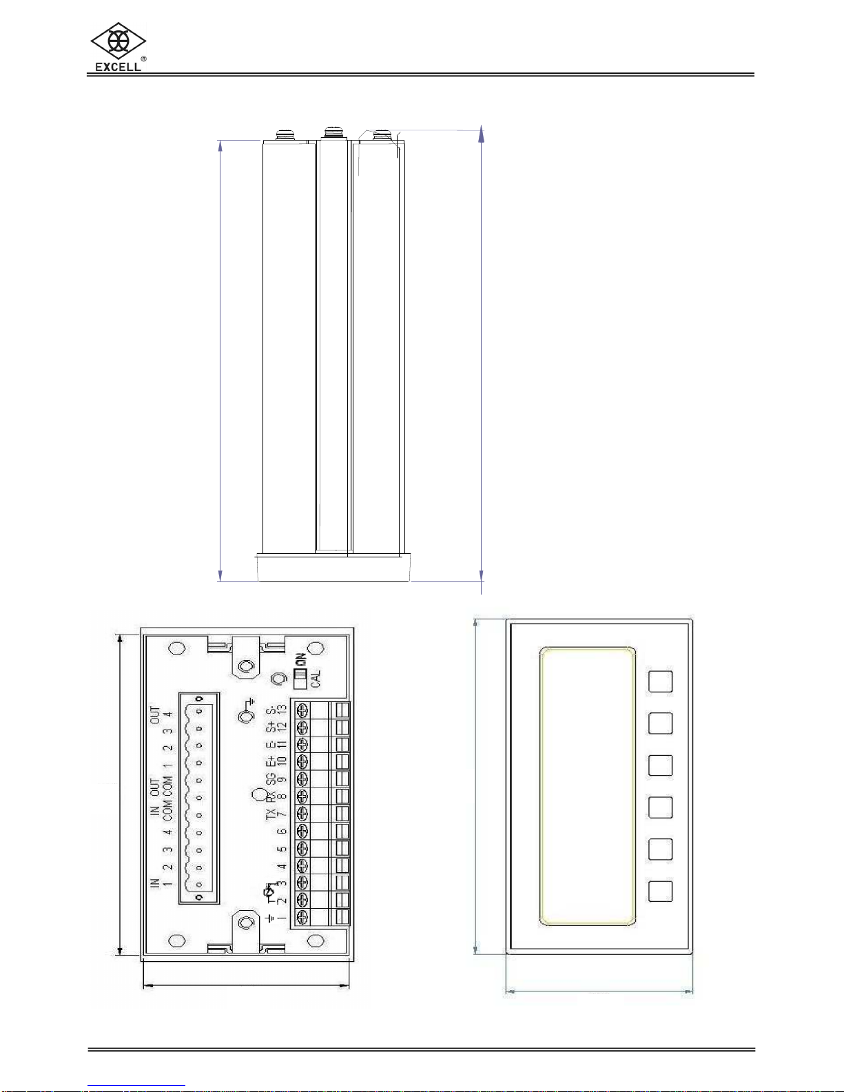
1-6 Dimensions (mm)
154
140
92
45
48
96
EX-2005C ZSME300000116
8
EXCELL PRECISION CO., LTD
.
First serial port interface
Function setting
CHAPTER 2 GENERAL FUNCTION
2-1 Function Setting Procedures
Hold key and then press key after power on
⇒Increase the flash value by one
⇒Decrease the flash value by one
⇒Move the cursor leftward
⇒Move the cursor rightward
⇒Confirm key
⇒Exit key
Refer to 5-1 for details
Qty
MR
F
Limit
Enter
Run
Stop
MC
F
Limit
Enter
F
Refer to 2-2 for details
Enter
Enter
EX-2005C ZSME300000116
9
EXCELL PRECISION CO., LTD
.
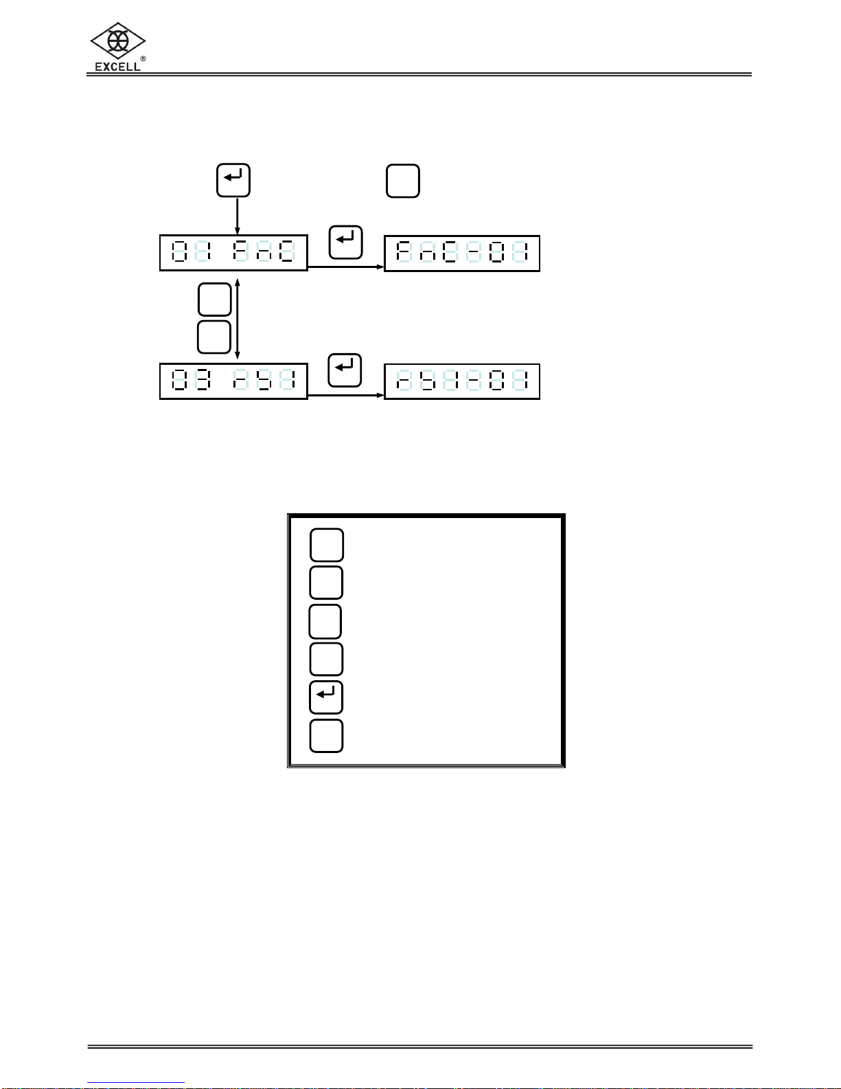
2-2 Function Setting
Press key
Input desired
parameter code
Press key
Display shows the
previous parameter
Input the desired
new parameter,
Press key
To continue the next function setting
Or press key to exit
⇒Increase the flash value by one
⇒Decrease the flash value by one
⇒Move the cursor leftward
⇒Move the cursor rightward
⇒Confirm key
⇒Exit key
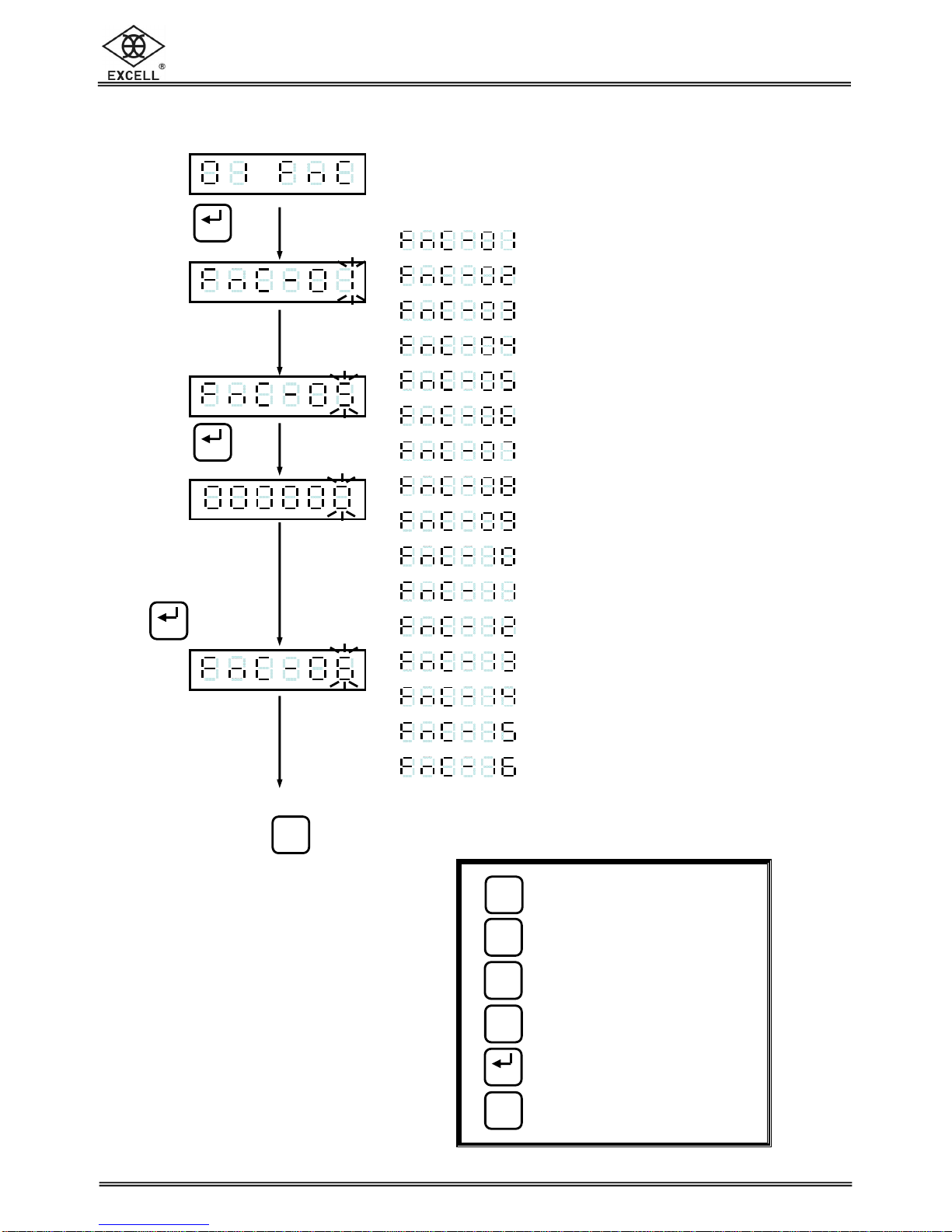
*Function Parameter Code
⇒Digital filter I
⇒Digital filter II
⇒Lock keypad function
⇒Password setting function
⇒Output signal (1) open time
⇒Output signal (2) open time
⇒Output signal (3) (4) open time
⇒Input signal (1) reaction time
⇒Input signal (2) reaction time
⇒Sorting and falling internal time
⇒Check-weighing time
⇒Weight comparison parameter zero range
⇒Weight sorting function setting
⇒Display rewrite frequency
⇒Turning on zero setting
⇒Sorting mode setting
Run
Stop
Enter
Enter
Enter
Qty
MR
F
Limit
Enter
Run
Stop
MC
EX-2005C ZSME300000116
10
EXCELL PRECISION CO., LTD
.
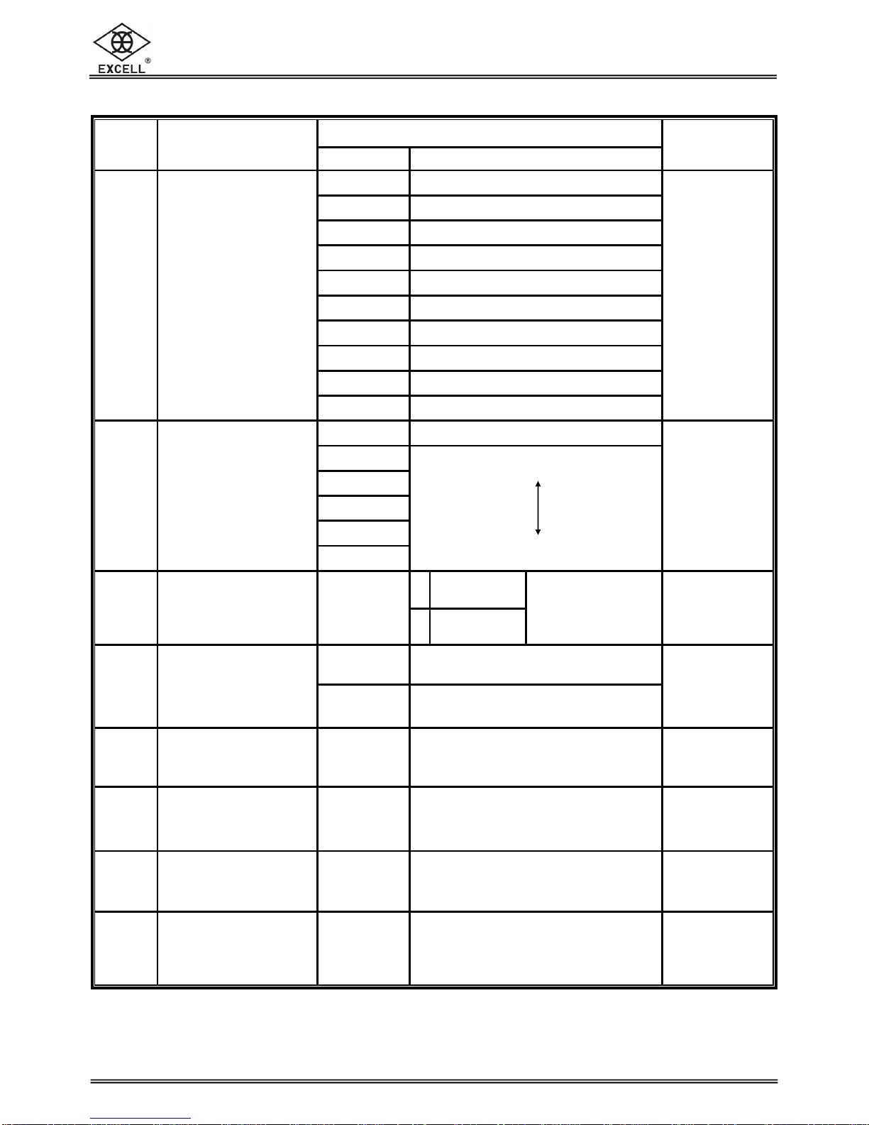
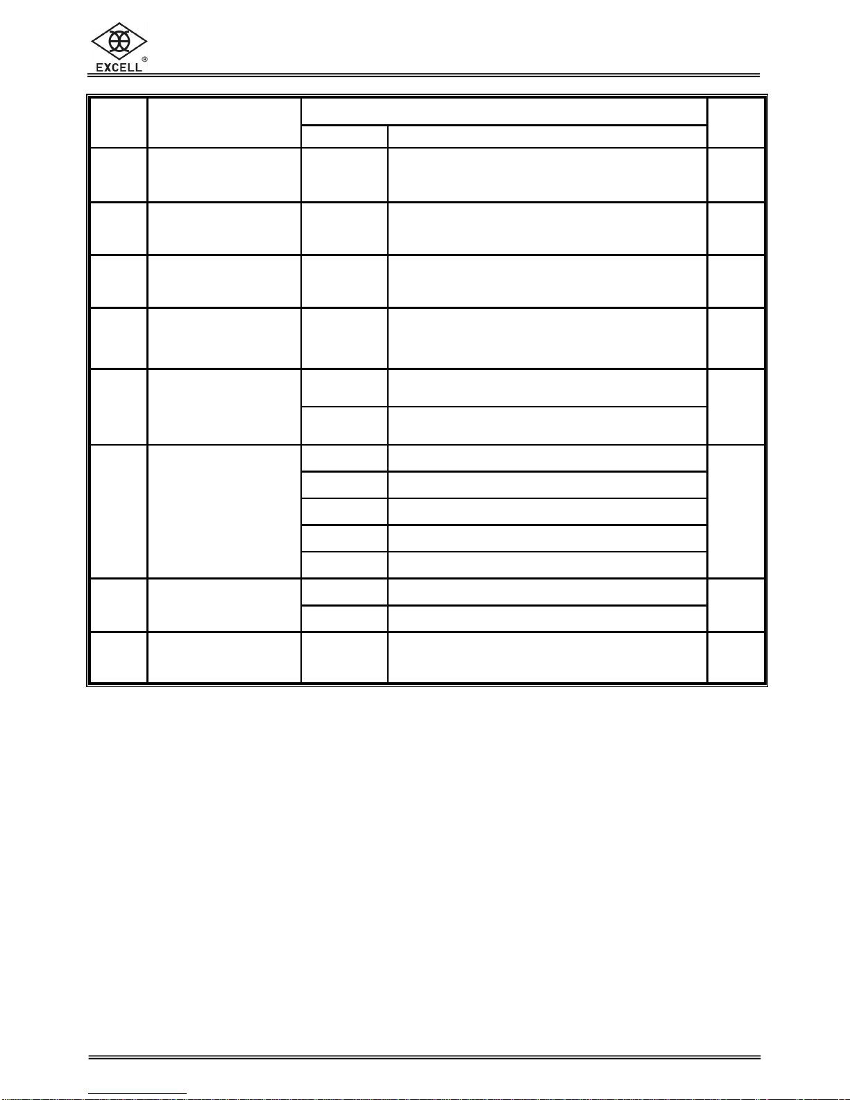
FNC Group function setting
Setting value
Item Function Parameter
Description
Default
0 5 Hz
1 4.17 Hz
2 2.5 Hz
3 2.08 Hz
4 1.25 Hz
5 1.04 Hz
6 0.63 Hz
7 0.52 Hz
8 0.31 Hz
FNC-01
Digital Filter I
9 0.26 Hz
4
0 Disable
1
2
3
4
FNC-02
Digital Filter II
5
weak
strong
2
0
Normal
(lock disable)
FNC-03
Lock Keypad 000 000
↓
111 111 1
Close
(lock enable)
The bits and front
panel key positions
are related to each
other
000 000
0 No password
FNC-04
Password setting 1 Set password 0
FNC-05
Output signal (1)
open time 0.0 ~ 25.5 s
Set output signal (1) 0.2
FNC-06
Output signal (2)
open time 0.0 ~ 25.5 s
Set output signal (2) 0.2
FNC-07
Output signal (3) (4)
open time 0.0 ~ 25.5 s
Set output signal (3) (4) 0.3
FNC-08
Input signal (1)
reaction time 0.0 ~ 25.5 s
Set delay time of input signal (1)
between reaction and operation 0.0
EX-2005C ZSME300000116
11
EXCELL PRECISION CO., LTD
.
Setting value
Item Function Parameter
Description Default
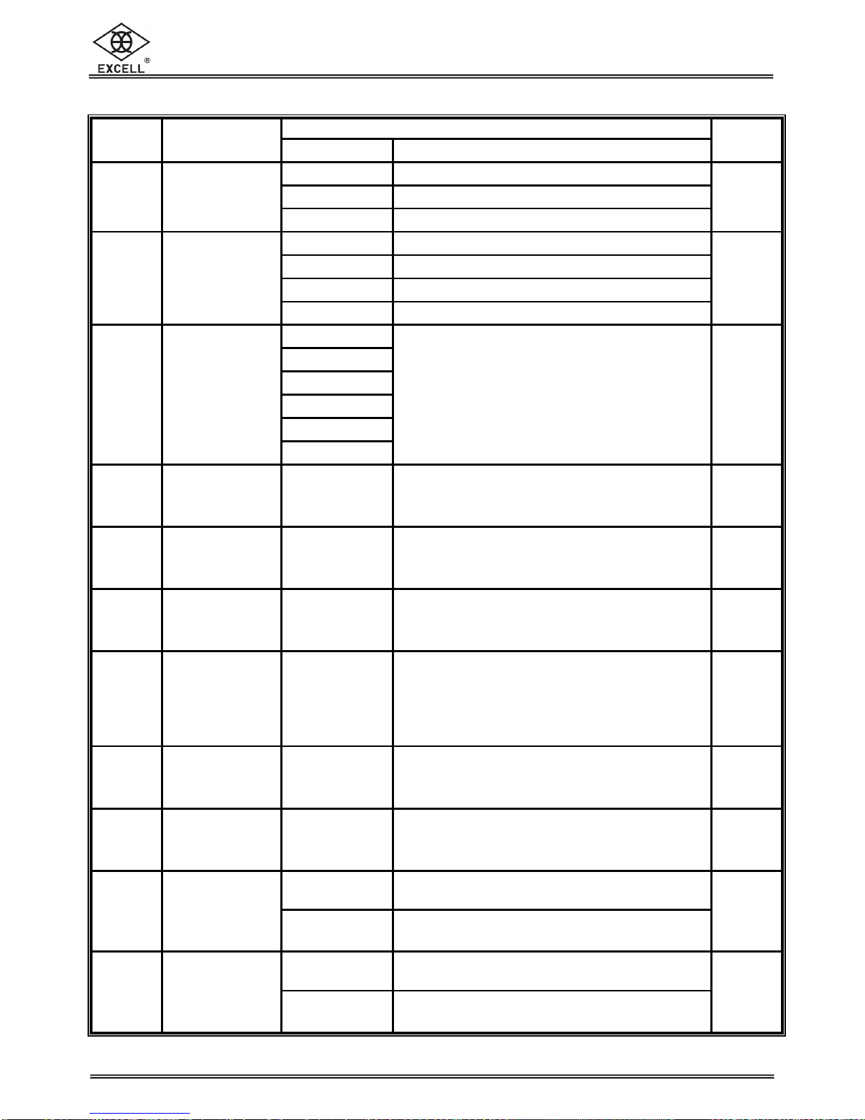
FNC-09
Input signal (2)
reaction time 0.0 ~ 25.5 s
Set delay time of input signal (2) between
reaction and operation 0.2
FNC-10
Sorting and falling
internal time 0.0 ~ 25.5 s
Internal time of each sorting and falling time
0.1
FNC-11
Check-
weighing time
0.0 ~ 25.5 s
Set check-weighing time 0.1
FNC-12
Weight comparison
parameter zero
range 0 ~ 255 d
Set zero range under check-weighing mode
(the number below the range is set as 0) 2
0 Memory ordering function disable
Single input and output enable
FNC-13
Weight sorting
function setting 1 Check-
weighing and ordering function enable
12 memorized weights at most
0
0 No limit
1 20 times/s
2 10 times/s
3 5 times/s
FNC-14
Display rewrite
frequency
4 1 times/s
0
0 Disable
FNC-15
Turning on zero
setting 1 Enable 0
FNC-16
Check-weighing
mode setting 0 - 1 Refer to Check-weighing mode
flowchart description 0
EX-2005C ZSME300000116
12
EXCELL PRECISION CO., LTD
.
CHAPTER 3 CALIBRATION DESCRIPTION
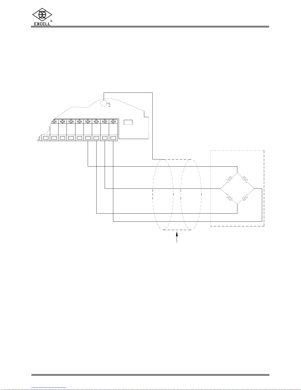
3-1 Load Cell Connection
2
22
2
When using a 4-wire cable to connect the load cell, the SEN+ and SEN- can
be left unconnected (see below diagram)
Shield
SIG+
Load cell cable
SIG-
EXC-
Load cell
EXC+
CAL
8
7
7
8
1010
99 11 13
12 ON
EX-2005C ZSME300000116
13
EXCELL PRECISION CO., LTD
.
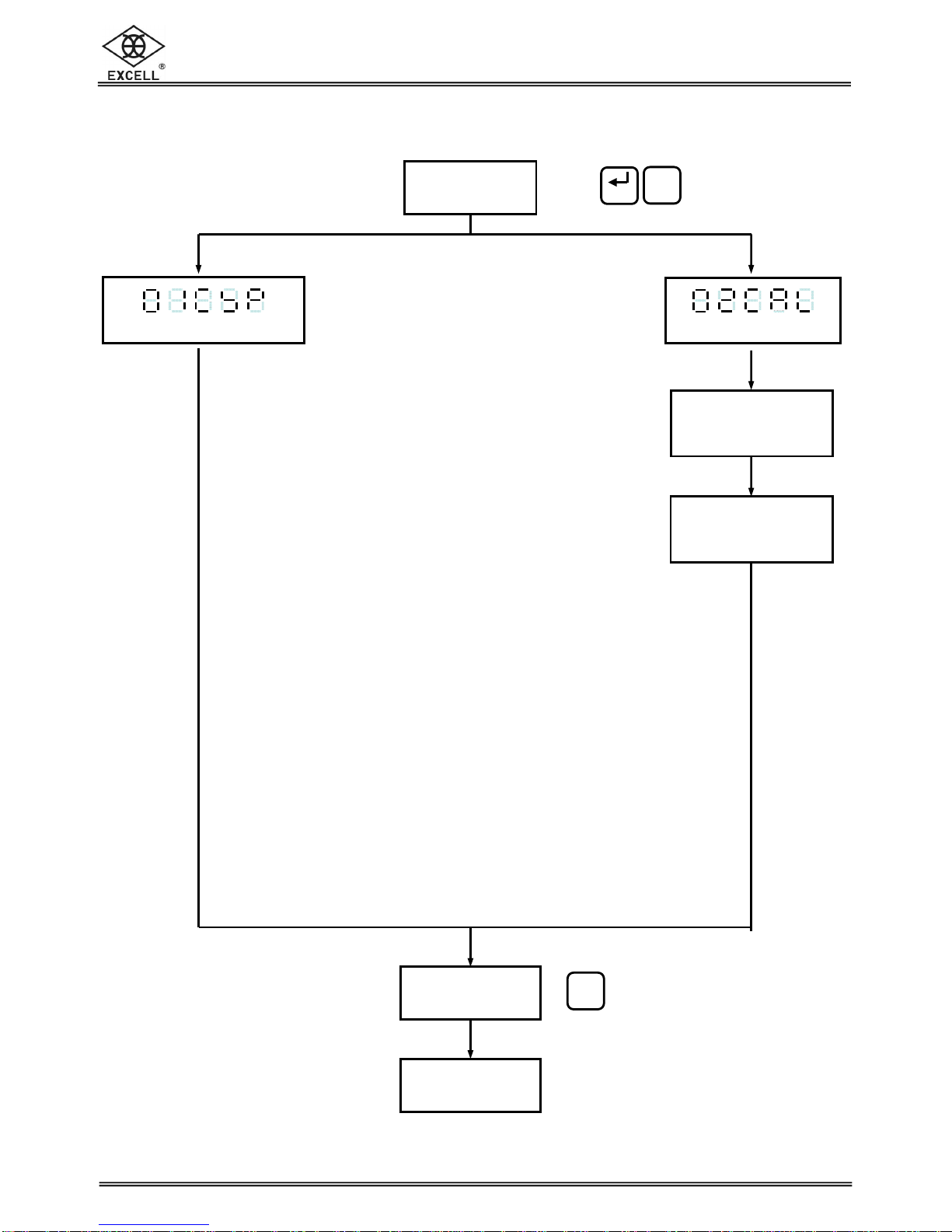
3-2 Parameter Setting And Calibration Flowchart
Press key
Specification calibration
Calibration
switch ON
Calibration
completed
General Calibration
Zero point voltage
calibration
Weight calibration
Calibration
switch ON
Limit
Enter
Run
Stop

EX-2005C ZSME300000116
14
EXCELL PRECISION CO., LTD
.
Specification
calibration
General calibration
Enter into general
calibration mode
Refer to
3-4 for details
Enter into specification
calibration mode
Refer to 3-3 for details
2
22
2Calibration Process
Press key
⇒Increase the flash value by one
⇒Decrease the flash value by one
⇒Move the cursor leftward
⇒Move the cursor rightward
⇒Confirm key
⇒Exit key
Qty
MR
F
Limit
Enter
Run
Stop
MC
Limit
Enter
Enter
Enter

EX-2005C ZSME300000116
15
EXCELL PRECISION CO., LTD
.
3-3 Specification Calibration
Press key
Input desired
parameter code
Press key
Display shows the
previous parameter
Input the desired
new parameter,
Press key
To continue the next function setting
Or press key to exit
⇒Increase the flash value by one
⇒Decrease the flash value by one
⇒Move the cursor leftward
⇒Move the cursor rightward
⇒Confirm key
⇒Exit key
*Calibration Parameter Code
⇒Unit
⇒Decimal point
⇒Min. Division
⇒Max. Capacity
⇒Zero range
⇒Time of zero tracking
⇒Range of zero tracking
⇒Investigation period of stability
⇒Investigation range of stability
⇒Zero and tare f
unction when the
weight is unstable
⇒Tare function availability when
gross weight is negative
Qty
MR
F
Limit
Enter
Run
Stop
MC
Enter
Run
Stop
Enter
Enter
EX-2005C ZSME300000116
16
EXCELL PRECISION CO., LTD
.
FNC Group function setting
Setting value
Item Function Parameter Description Default
0 None
1 g
CSP-01
Unit 2 kg 1
0 None
1 1 decimal point
2 2 decimal point
CSP-02
Decimal point
3 3 decimal point
1
1
2
5
10
20
CSP-03
Division
50
Division size 1
CSP-04
Max. Capacity
999 999
↓
000 000 Division size 999 999
CSP-05
Zero range 0 ~ 30 0 ⇒full range 1 ~ 30 ⇒±1% ~ ±30%
Zero range = calibration zero point ±(Max.
capacity×setting value %) 0
CSP-06
Time of zero
tracking 0.0 ~ 5.0 s Time and range of zero tracking should be
use at the same time. If the time is set to
0.0, the zero tracking function is disabled 1.0
CSP-07
Range of zero
tracking 0 ~ 9
Range of zero tracking = (setting
value×½)D, D=division
Range and time of zero tracking should be
use at the same time. If the range is set to 0,
the zero tracking function is disabled
9
CSP-08
Investigation
period of
stability
0.0 ~ 5.0 s Investigate time and range should be use
at the same time. If the time is set to 0.0,
the investigate time is disabled 2.0
CSP-09
Investigation
range of
stability
0 ~ 9 Investigate time and range should be use
at the same time. If the range is set to 0,
the investigate range is disabled 2
0 Enable
CSP-10
Zero and tare
function when
weight is
unstable
1 Disable 0
0 Enable
CSP-11
Tare function
available when
gross weight is
negative
1 Disable 0

EX-2005C ZSME300000116
17
EXCELL PRECISION CO., LTD
.
3-4 General Calibration
Press key to enter into
general calibration mode
Press key
Zero Calibration
No weight on the platform
or in the hopper
Press key
After 5 seconds
After 2 seconds
Weight Calibration
Use the front panel to key in the
weight value
Place the weight on the platform or
inside the hopper
After the weight is stable
Press key
After 5 seconds
Press key
General calibration completes
Zero calibration only, press key to escape after the display shows
.
Span calibration only, press key entering directly to span calibration after the display
shows .
Please refer to error message during calibration of the display show
.X .
⇒Increase the flash value by one
⇒Decrease the flash value by one
⇒Move the cursor leftward
⇒Move the cursor rightward
⇒Confirm key
⇒Exit key
kg
kg
. . . . .
kg
. . . . .
kg
Enter
Qty
MR
F
Limit
Enter
Run
Stop
MC
Run
Stop
Run
Stop
Run
Stop
Enter
Enter
Enter
EX-2005C ZSME300000116
18
EXCELL PRECISION CO., LTD
.
3-5 Error Messages
.
⇒Load Cell output voltage is lower than - 0.1mV/V or higher than 4 mV/V
.
⇒Weight value ≤previous weight value
.
⇒Actual measured weight value ≤previous weight value
.
⇒Setting value is 0
.
⇒mV/V value entered is higher than investigation range
.
⇒mV/V value entered is too small (SPAN – Zero is lower than 0 mV/V)
.
⇒Displayed resolution is less than 0.12 µ
µµ
µV/d
When the above messages appear, please contact your supplier for
professional help and service.
EX-2005C ZSME300000116
19
EXCELL PRECISION CO., LTD
.
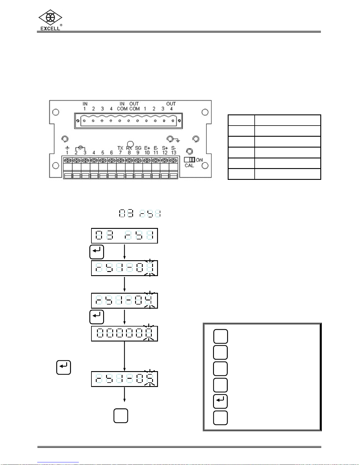
CHAPTER 4 INTERFACE DESCRIPTION
Serial input / output interface (built-in)
Pin location and setting
1. Built-in RS-232 and Current-loop
Function setting
First serial port interface
setting procedures
Press key
Input desired
parameter code
Press key
Display shows the last setting
Input a new desired parameter
Press key
Continue to next function setting or
press key to exit
PIN Function
5 Current loop in
6 Current loop out
7 TXD
8 RXD
9 SG
⇒Increase the flash value by one
⇒Decrease the flash value by one
⇒Move the cursor leftward
⇒Move the cursor rightward
⇒Confirm key
⇒Exit key
Qty
MR
F
Limit
Enter
Run
Stop
MC
Enter
Run
Stop
Enter
Enter
Table of contents
Other Excell Accessories manuals


Popular Accessories manuals by other brands

Stahl
Stahl SolConex 8579/31 Series operating instructions

ESTEBAN
ESTEBAN CITY POP EDITION Use Instructions Leaflet

Micro Detectors
Micro Detectors CR0 Series Installation and operation manual

Craftsman
Craftsman 183.287660 Safety and assembly instructions

Burkert
Burkert SE30 Ex Namur instruction manual

ROSE DISPLAYS
ROSE DISPLAYS ROPOLE-SPIDER instructions


