Excell EX2005 User manual
User Manual
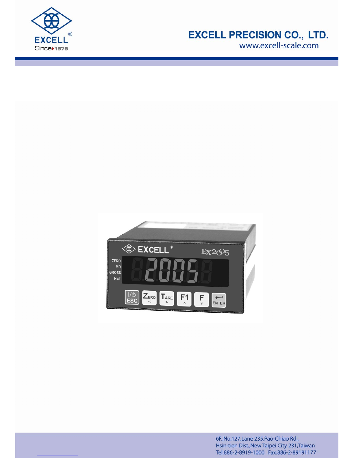
EX2005
© Excell Precision Limited 2015. All rights reserved Worldwide.
The information contained herein is the property of Excell Precision Limited and is supplied
without liability for errors or omissions. No part may be reproduced or used except as
authorised by contract or other written permission. The copyright and the foregoing
restriction on reproduction and use extend to all media in which the information may be
embodied.

1
040
1
1210
ZSME
4
00000
00
3
EXCELL PRECISION CO., LTD
CONTENT
Safety...................................................................................................................................3
Features...............................................................................................................................3
Chapter 1 Front and Rear Panel Specifications..........................................................................4
1-1 Front panel .............................................................................................................4
1-2 Rear panel..............................................................................................................4
1-3 Keypad Description ................................................................................................5
1-4 A/D Conversion.......................................................................................................5
1-5 Power supply..........................................................................................................5
1-6 Dimensions.............................................................................................................6
Chapter 2 General Function Guide......................................................................................7
2-1 Function Setup and Operation Procedures ............................................................7
2-2 Error Messages (Display in General Function setting) ...........................................8
2-3 Function Setting .........................................................................10
Chapter 3 Calibration.........................................................................................................13
3-1 Load Cell Connection...........................................................................................13
3-2 Parameter Setting and Calibration Flow Chart .....................................................14
3-3 MODBUS Calibration............................................................................................16
3-4 Specification calibration .............................................................17
3-5 General Calibration ....................................................................19
3-6 Linearity calibration ....................................................................20
3-7 Digital calibration ....................................................................22
Chapter 4 Weight Comparison Procedures .......................................................................23
4-1 Function Configuration Menu ...............................................................................23
4-2 Check Weighing Configuration.............................................................................26
4-3 Batching Signal Outputs.......................................................................................29
4-4 Normal batching flow chart (SQ-01=1) .................................................................30
4-5 Loss-in Weight flow chart (SQ1=2).......................................................................31
4-6 Hi, OK, Lo output flowchart...................................................................................32
4-7 Normal batching (built-in program) flowchart (SQ-01=4)......................................33
4-8 Loss-in Weight (built in program) (SQ-01=5)........................................................34
4-9 Hold mode (SQ-01 = 6) ........................................................................................35
4-9-1 Hold mode flow chart .................................................................................36
4-9-2 Hi, OK, Lo comparison...............................................................................37
4-10 Totalizing (ACCU.) Auto / Transmit .....................................................................37

2
04011210
ZSME
4
00000
003
EXCELL PRECISION CO., LTD
Chapter 5 Interface............................................................................................................38
5-1 Serial Input / Output Interface (default OP-01).....................................................38
5-2 BCD parallel output interface (OP-02) ......................................46
5-3 Analogue Current / Voltage Output Interface (OP-03) ..........................................48
5-4 External Parallel Input / Output Interface..............................................................50
Chapter 6 Maintenance......................................................................................................55
6-1 Restore All Parameters to Their Default Factory Values.......................................55
6-2 Maintenance Function Parameters.......................................................................55
6-2-1 Restore the function parameter back to its default value............................56
6-2-2 Clear zero compensation and TARE values...............................................56
6-2-3 Clear batch setting.....................................................................................56
6-2-4 Display zero voltage (mV/V).......................................................................56
6-2-5 Clear batch setting.....................................................................................56
6-3 Test mode.............................................................................................................57
6-3-1 7-Segment display testing..........................................................................58
6-3-2 Keypad and calibration SW testing ............................................................58
6-3-3 Display A/D internal value display ..............................................................58
6-3-4 RS-232 serial loop back testing..................................................................58
6-3-5 EEPROM memory testing..........................................................................58
6-3-6 Option interface card testing ......................................................................58
Appendix 1 Description of 7-Segment Characters.............................................................60
Appendix 2 Function Table.................................................................................................61
Appendix 3 MODBUS DataAddress Table I ......................................................................70
Appendix 4 MODBUS DataAddress Table II .....................................................................71
Appendix 5 Examples for Input and Output of Modbus......................................................72

3
040
1
1210
ZSME
4
00000
00
3
EXCELL PRECISION CO., LTD
Safety
zWhen the instrument is installed, connect an earth bonding conductor from FG to the
earth connection marked “ ”.
zDisconnect the mains power supply before opening the instrument housing.
zTo install the optional interface cards, it is necessary to disconnect the mains power
supply and fit a yellow/green earth bonding cable to the rear panel.
zBefore turning the power on ensure the supply voltage is within the acceptable range,
DC24 V.
zThe operating ambient temperature range is 0 oC ~ 40 oC (32 °F ~ 104 °F).
Features
EX2005 has a wide range of applications from batching to simple weighing.
Features:
Stand alone batching mode or connect to PLC for external system control
Built in batching / dosing functions
Manual / automatic discharge operation
Set cycle times in a batch
Totalise weight and number of cycles
Key in the signal voltage value (mV / V) directly via the keypad, no need to apply
any weight to the bottom work to calibrate the weigher
Display load cell output voltage (mV / V) for future maintenance
Adjustable filter
RS232C bi-directional and RS485 communication
Built-in MODBUS (RTU) format
Interface options:
OP-01 RS-422 / RS-485 / RS-232 serial interface
OP-02-1 BCD parallel output interface (Open collector output)
OP-02-2 BCD parallel output interface (TTL output)
OP-03 16 Bit Analogue current/voltage output interface
(4~20mA/0~10V)
OP-04 Control I/O (4 In / 4 Out) + Setpoint In (BCD code)
OP-05 Control I/O (8 In / 8 Out)

4
040
1
1210
ZSME
4
00000
00
3
EXCELL PRECISION CO., LTD
Chapter 1 Front and Rear Panel Specifications
1-1 Front panel
Display
•6 digits, bright red, 7 segment LED display, character height 16mm (0.63”).
•Display can be switched between Gross Weight / Net Weight / Totalised Weight /
Number of transactions in the total.
Indication icons “◄”
ZERO ◄:Zero Indication
MD ◄:Unstable weight Indication
GROSS ◄: Gross weight Indication
NET ◄: Net weight Indication
♦The indicator is supplied with suitable labels to customise the icon displays.
♦Refer to FNC-06 ~ FNC-09 for the various options available.
Weighing Units
zWeighing Units kg / g / t / lb.
1-2 Rear panel
zCalibration Switch set to the left is “OFF” and to the right is “ON”
Terminal Block Calibration Switch
z13 Way Terminal Block
1st FG
2nd DC+
3rd DC-
4th NC
5th TX
6th RX
7th SG
8th E+
9th SEN+
10th E-
11th SEN-
12th SIG +
13th SIG -
Display Area
Weight Unit
Indication

5
040
1
1210
ZSME
4
00000
00
3
EXCELL PRECISION CO., LTD
1-3 Keypad Description
:
When entering data or reference setting, it means “ESC”.
In the normal operation, it puts the indicator in standby mode or escape.
Entering standby mode: All of the display (except ZERO “3” symbol)
and serial data output are disabled.
Escape from standby mode: Re-power on mains for normal operation.
Function FNC-03 can be used to selectively disable individual keys.
Zero operation, will be limited by functions CSP-05 and CSP-10.
Zero operation, will be limited by functions CSP-10 and CSP-11.
1-4 A/D Conversion
* Input Sensitivity
* Internal Resolution
* Max. Sampling Speed
* Application Range
* Load Cell Excitation Voltage
: Over 0.12μV/d
: 1 / 1 000 000
: 120 times/s.
: - 0.1 ~ 4.0 mV / V
: 5 V DC ±5%, 120 mA
(Up to eight (8) 350 Ωload cells can be connected)
1-5 Power supply
♦DC24 V
♦Power consumption is about 10 VA
:When parameter setting, it moves the flashing digit left.
In the normal mode, it performs a Zero operation.
:When parameter setting, it moves the flashing digit right.
In the normal mode, it performs a semi-auto Tare operation.
:When parameter setting, it increments the flashing digit or steps up the
select item.
In the normal mode, it accesses the FNC-05 setting.
:When parameter setting, it decrements the flashing digit or steps down
the select item.
In the normal mode, it accesses the FNC-04 setting.
:
Confirm / enter key.

6
040
1
1210
ZSME
4
00000
00
3
EXCELL PRECISION CO., LTD
1-6 Dimensions
7
040
1
1210
ZSME
4
00000
00
3
EXCELL PRECISION CO., LTD
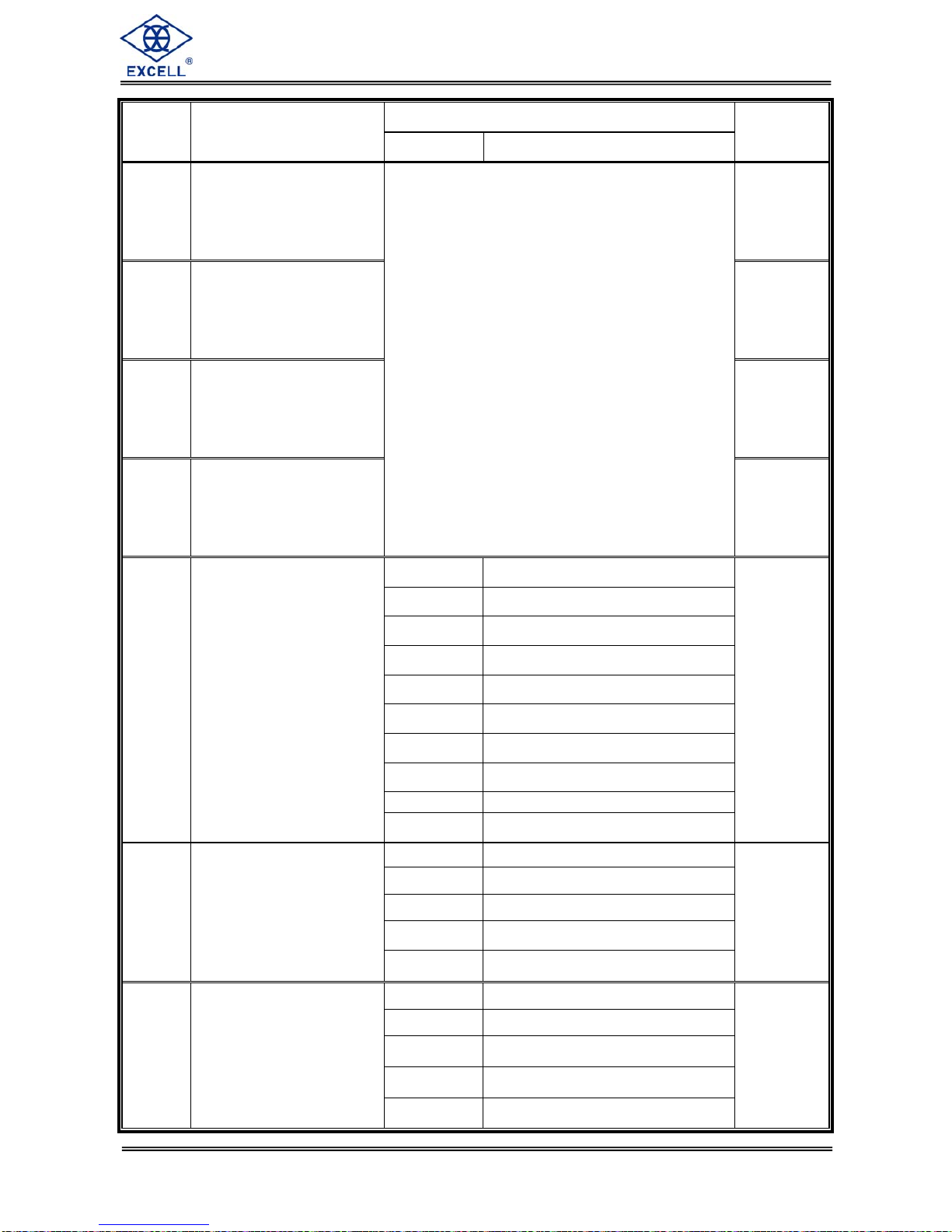
Chapter 2 General Function Guide
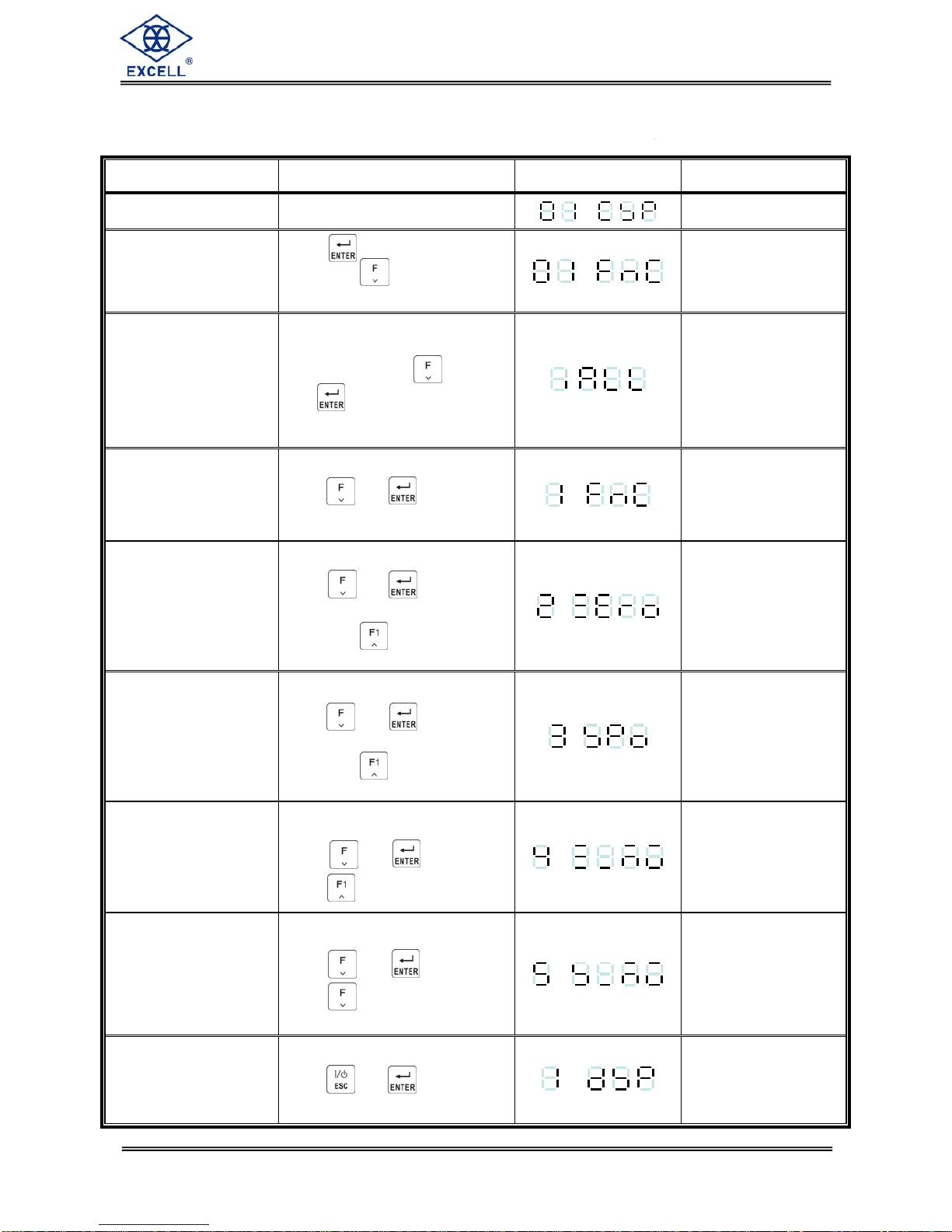
2-1 Function Setup and Operation Procedures
Function Operation Display Description
Enter calibration mode Turn the calibration switch to “ON” See 3-2 for details
Enter function setting
Press not release,
then press key
after the power is turned on
See 2-2 for details
Reset all parameters
back to default
Turn the power on then turn the
calibration switch to “ON” then
press and hold the
and keys during the
self-testing sequence
. See 6-1 for details
Reset general function
parameters back to
default
Turn the power on and
press and keys
during self-testing sequence
See 6-2-1 for details
Clear zero point
compensation and tare
value
Turn the power on and
press and keys
during self-testing sequence, and
then press key
See 6-2-2 for details
Clear setpoint parameter
setting
Turn the power on and
press and keys
during self-testing sequence, and
then press two times
See 6-2-3 for details
Value of zero point
voltage(mV / V)
Turn the power on and
Press and ,then
press key three times
See 6-2-4 for details
Value of Span voltage
(mV / V)
Turn the power on and
Press and , then
Press key
See 6-2-5 for details
Entering to test mode
Turn the power on and
press and keys
during self-testing sequence
. See 6-3 for details

8
040
1
1210
ZSME
4
00000
00
3
EXCELL PRECISION CO., LTD
Function Operation Display Description
Check weighing setpoint
parameter setting
Press the key to set
the parameter of FUNC.4 to 1 in
the normal mode
.
or
.
See 4-2 for details
Key actions in function set up mode
⇒Increases the number of the flashing digit
⇒Decreases the number of the flashing digit
⇒Moves the flashing digit one space to the left
⇒Moves the flashing digit one space to the right
⇒Saves the configuration
⇒Quits set up mode / Escape
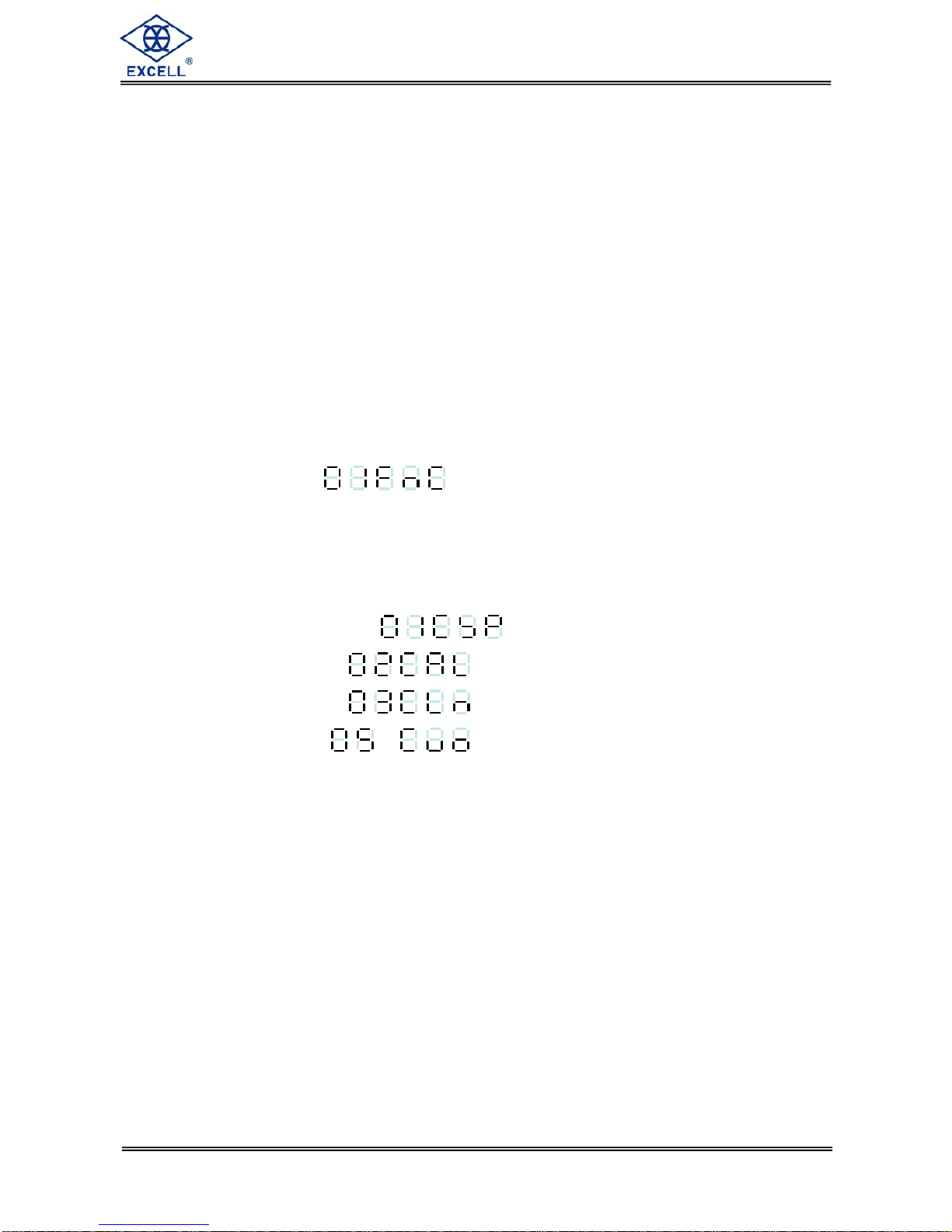
2-2 Error Messages (Display in General Function setting)
. ⇒Load Cell output voltage <- 0.1m V / V or >4mV / V
. ⇒Weight value ≤previous weight value
. ⇒Actual measured weight value ≤previous weight value
. ⇒Setting value 0
. ⇒mV / V value entered >measuring range
. ⇒mV / V value entered is too small (SPAN – Zero <0 mV / V)
. ⇒Displayed resolution is less than 0.12 μV / division

9
040
1
1210
ZSME
4
00000
00
3
EXCELL PRECISION CO., LTD
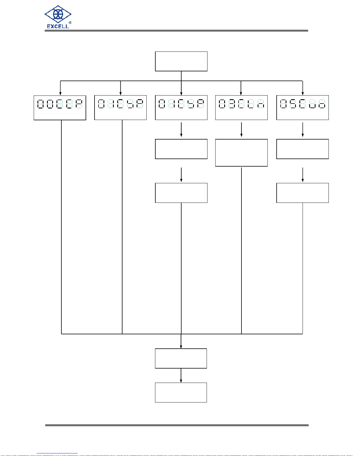
Function Setting
First Serial Port Interface
Second Serial Port
Interface
BCD Parallel Port output
interface
A
nalogue current / voltage
output interface
External parallel control
input interface
External parallel trip output
interface
Function Setting Procedures
With weight displayed press and hold the key. Then, press key
See 5-1 for details
See 5-2 for details
See 5-3 for details
See 5-1 for details
See Function Setting 2-2
for details
See Chapter 4 for details
See 5-4 for details
See 5-4 for details
Set Point Procedure
10
040
1
1210
ZSME
4
00000
00
3
EXCELL PRECISION CO., LTD
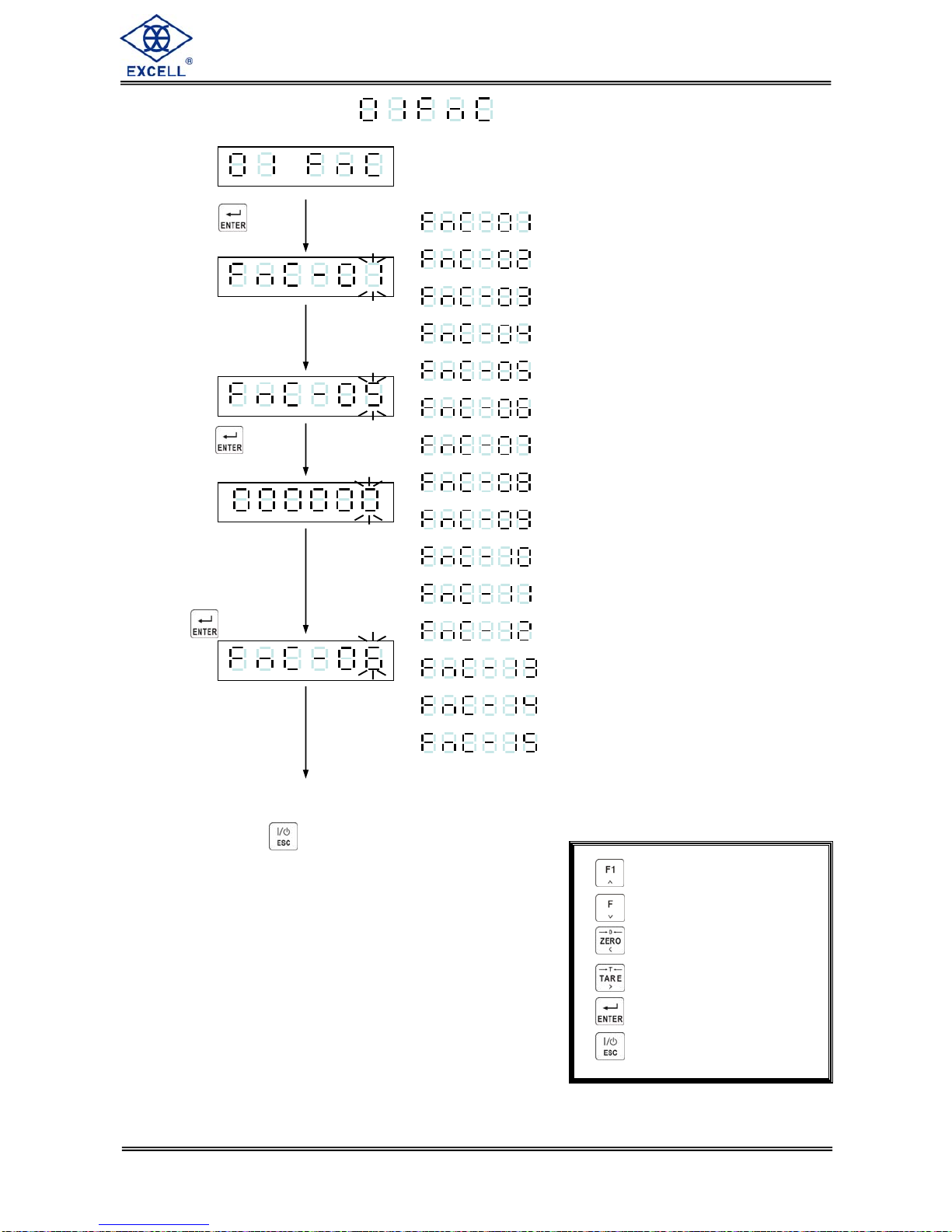
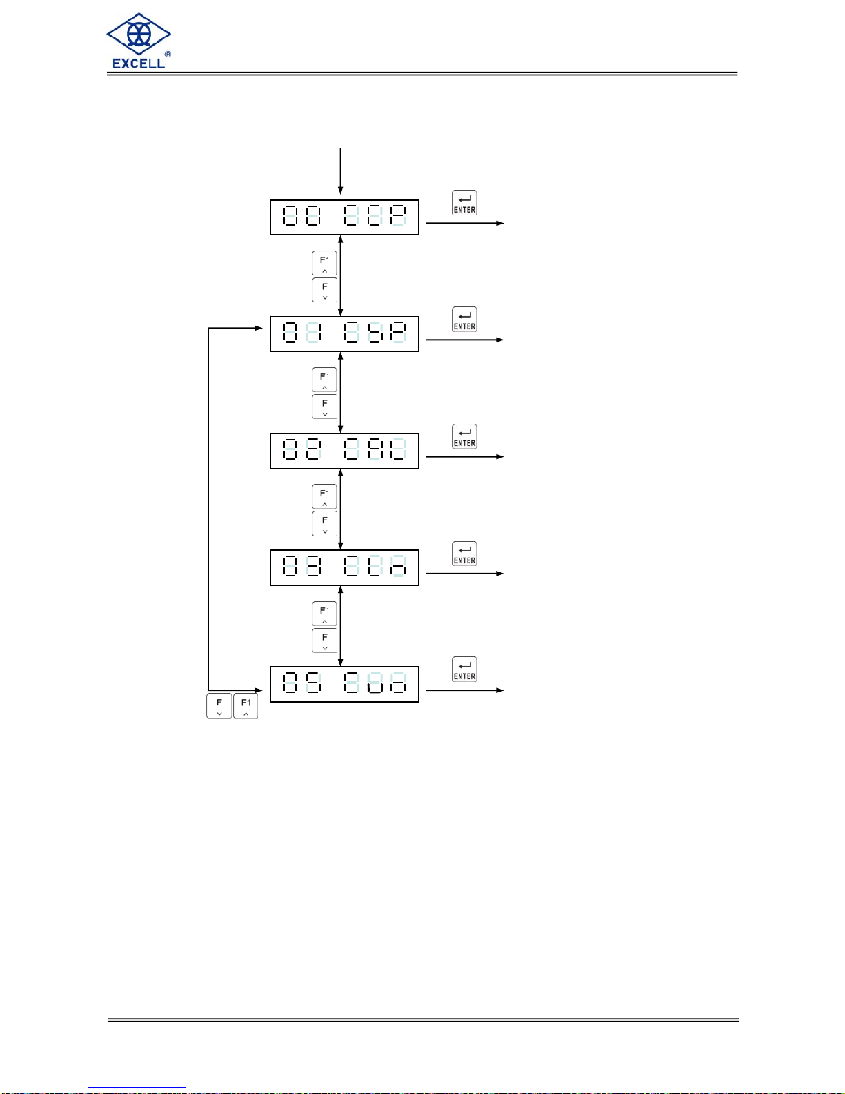
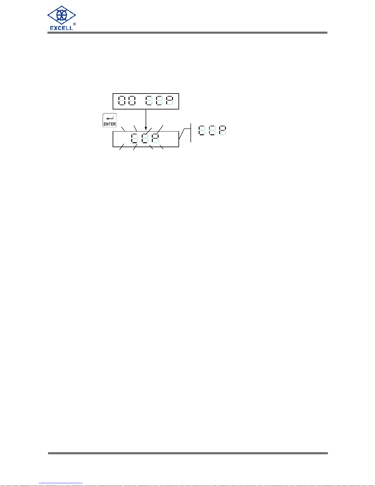
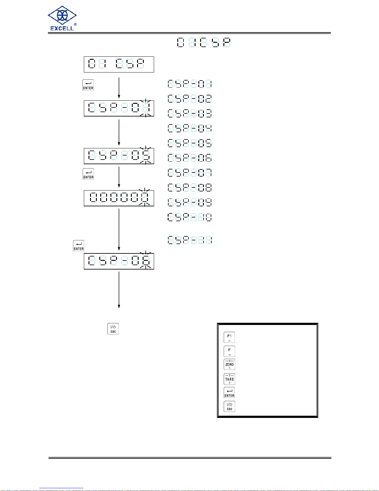
2-3 Function Setting
Press key
Input desired
Parameter code
Press key
Display shows the
previous parameter
code. Input the new
code as required
Press key
To continue the next function setting
or press key to escape
⇒Increment flashing digit
⇒Decrement flashing digit
⇒Move flashing point left
⇒Move flashing point right
⇒Store data in memory
⇒Exit / Escape
*Function Parameter code
⇒Digital Filter I
⇒Digital Filter II
⇒Lock keypad function
⇒“F” function setting
⇒“F1” function setting
⇒Front panel indication “◄” setting (first)
⇒Front panel indication “◄” setting (second)
⇒Front panel indication “◄” setting (third)
⇒Front panel indication “◄” setting (fourth)
⇒Terms of back to zero
⇒Hold
⇒Rate for display rewrite
⇒Turn-on zero setting
⇒Stand-by mode setting
⇒Zero function record setting

11
040
1
1210
ZSME
4
00000
00
3
EXCELL PRECISION CO., LTD
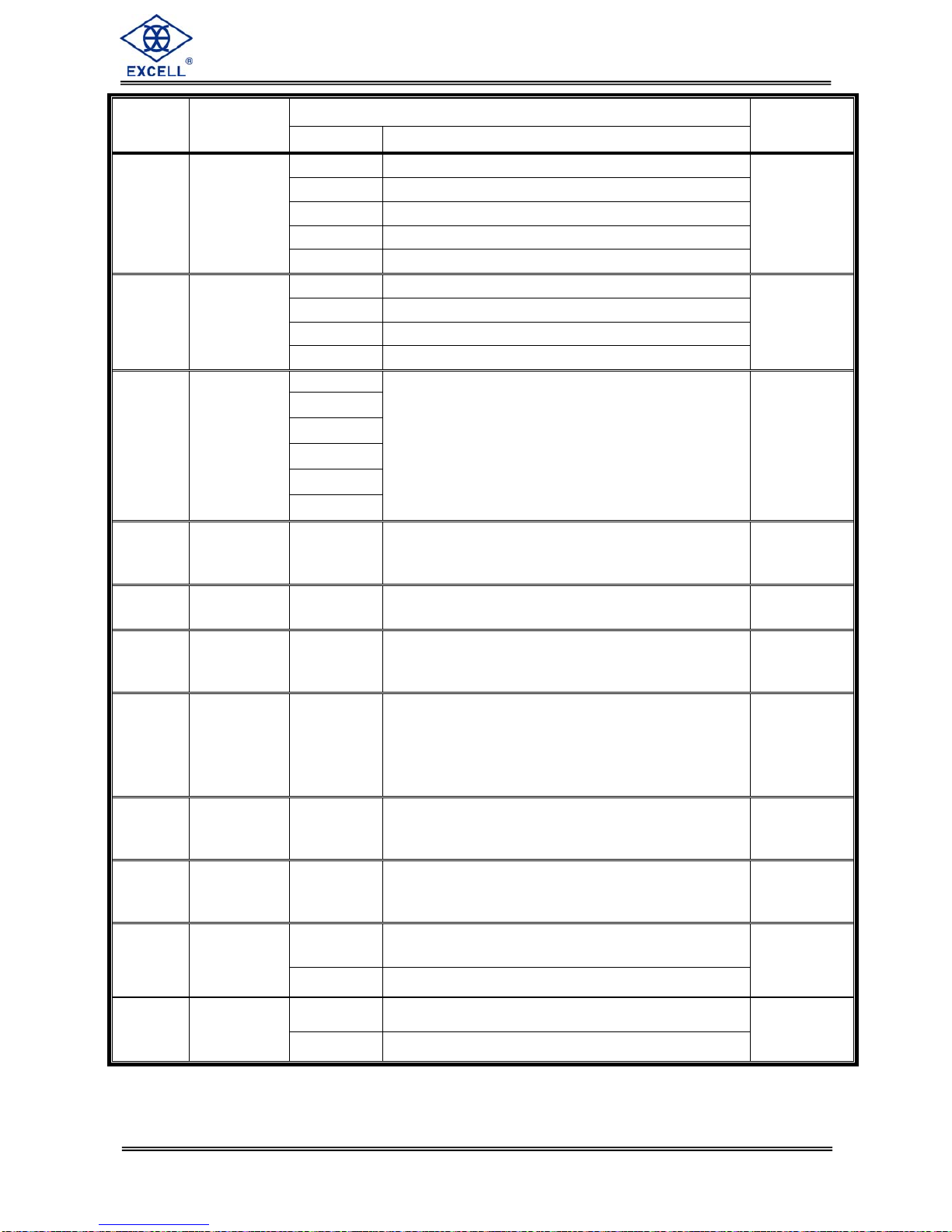
FNC Group function setting
Setting value
Item Function
Parameter Description Default
0 5 Hz
1 4.17 Hz
2 2.5 Hz
3 2.08 Hz
4 1.25 Hz
5 1.04 Hz
6 0.63 Hz
7 0.52 Hz
8 0.31 Hz
FNC-01 Digital Filter I
9 0.26 Hz
4
0 Disabled
1
2
3
4
FNC-02 Digital Filter II
5
Less filter
Greater
2
0Normal
(lock disable)
FNC-03 Key – Locked
000000
↓
111111 1Close
(lock enable)
The bits and front
panel key
positions are
related to each
other
000000
FNC-04 “F” function setting 1
FNC-05 “F1” function setting
Parameter ⇒Description
0 ⇒Display Net / Gross weight
1 ⇒Setpoint parameter setting
2⇒Tare reset
3⇒Manual serial, parallel print output
4⇒Start load
5⇒Stop load
6⇒Start comparison
7⇒Unload command
8⇒Totalise weight and counts
command
9⇒Clear totalised weight and counts
10 ⇒Hold mode
11 ⇒Escape Hold mode(I / O DSP)
12 ⇒Convert to Gross / Net / totalised
weight / totalised Count
0
12
040
1
1210
ZSME
4
00000
00
3
EXCELL PRECISION CO., LTD
Setting value
Item Function
Parameter Description
Default
FNC-06 Front panel indication “◄”
setting (top) 0
FNC-07 Front panel indication “◄”
setting (next to top) 1
FNC-08 Front panel indication “◄”
setting (next to bottom) 2
FNC-09 Front panel indication “◄”
setting (bottom)
Parameter ⇒Description
0⇒Zero
1⇒MD
2⇒Gross
3⇒Net
4⇒Totalised weight (Accu. V)
5⇒Totalised transactions (Accu. C)
6⇒SP1
7⇒SP2
8⇒SP3
9⇒Hi
10 ⇒OK
11 ⇒Lo
12 ⇒Under
13 ⇒Over
14 ⇒Discharge
15 ⇒Running
16 ⇒Hold
3
0 5 d
1 10 d
2 20 d
3 40 d
4 60 d
5 80 d
6 100 d
7 150 d
8 200 d
FNC-10 Return to zero band
(d: refer to CSP-03)
9 250 d
0
0 Hold
1 Peak hold (positive 1)
2 Peak hold (negative)
3 Peak hold (absolute value)
FNC-11 Hold
4 Peak hold (positive 2)
0
0 No limitation
1 20 times/s
2 10 times/s
3 5 times/s
FNC-12 Rate for display rewrite
4 1 time/s
0

13
040
1
1210
ZSME
4
00000
00
3
EXCELL PRECISION CO., LTD
Setting value
Item Function
Parameter Description
Default
0 Disable
FNC-13 Turn-on zero setting
1 Enable
0
0 Disable all the functions under
stand-by mode
FNC-14 Stand-by mode setting
1
Only turn off display but not
disable other functions under
stand-by mode
0
0 Zero point record not saved into
EEPROM
FNC-15 Zero function record
setting 1 Zero point record saved into
EEPROM
0
Chapter 3 Calibration
3-1 Load Cell Connection
14
040
1
1210
ZSME
4
00000
00
3
EXCELL PRECISION CO., LTD
Specification
Calibration Linearity
Calibration Digital
Calibration
MODBUS
Calibration
3-2 Parameter Setting and Calibration Flow Chart
Calibration
Switch ON
Zero Point Voltage
Calibration
Span Voltage
Calibration
Select 1 Point for
Weight Calibration
(1P~5P)
Calibration Switch
OFF
Calibration
Completed
Zero point
Calibration
Weight Calibration
General
Calibration
15
040
1
1210
ZSME
4
00000
00
3
EXCELL PRECISION CO., LTD
Calibration process
Before the Linearity Calibration, the General Calibration should be completed.
Calibration Switch set to ON
Entering the specification
calibration, see 3.4 for
details
Entering the General
calibration, see 3.3 for
details
Entering the General
calibration, see 3.5 for
details
Entering the linearity
calibration, see 3.6 for
details
Entering the Digital
calibration, see 3.7 for
details
Spec. Calibration
General Calibration
Linearity Calibration
Digital calibration
MODBUS Calibration
16
040
1
1210
ZSME
4
00000
00
3
EXCELL PRECISION CO., LTD
3-3 MODBUS Calibration
2RS1-02 set as “4” (MODBUS RTU mode)
RS1-07 set as “01” (address)
Eg:
Zero calibration
Input 01050423FF007CC0 ←zero calibration
Reading calibration status
Input 0101004100565AC1D ←Refer to “Appendix 3: MODBUS data
address table”
The zero calibration is finished, and there should be no Err message
appeared.
Span calibration
Input weight calibration value 3000
Input 0110044C0001020BB8EADE ←Input weight calibration value 3000
Put 3kg on the platter
Span calibration
Input 01050424FF00CD01 ←Span calibration
Reading calibration status
Input 0101004100565AC1D ←Refer to “Appendix 3: MODBUS data
address table”
The span calibration is finished, and there should be no Err message
appeared.
Press key
Keep flashing
17
040
1
1210
ZSME
4
00000
00
3
EXCELL PRECISION CO., LTD
3-4 Specification calibration
Press key
Key in calibration
code
Press key
Display shows the
previous parameter
code. Input the new
code as required
Press key
To continue the next function setting
or press key to escape
⇒Increment flashing digit
⇒Decrement flashing digit
⇒Move flashing point left
⇒Move flashing point right
⇒Store data in memory
⇒Exit / Escape
*Calibration parameter code
⇒Unit
⇒Decimal Point
⇒Min. Division
⇒Max. Capacity
⇒Zero Range
⇒Time of Zero tracking
⇒Range of Zero tracking
⇒Investigate period of unstable
⇒Investigate range of unstable
⇒Function Zero and Tare when the
weight is unstable
⇒Tare function availability when
gross weight is negative
18
040
1
1210
ZSME
4
00000
00
3
EXCELL PRECISION CO., LTD
Setting value
Item Function
Parameter Description
Default
0 None
1 g
2 Kg
3 t
CSP-01 Unit
4 lb
2
0 None
1 1 Decimal Point
2 2 Decimal Point
CSP-02 Decimal
Point
3 3 Decimal Point
0
1
2
5
10
20
CSP-03 Division
50
Division size 1
CSP-04 Max.
Capacity
999999
↓
000000
Max. capacity 999999
CSP-05 Zero range 0 =full range
(±1%~30%)
Zero range = calibration zero point ±(Max.
capacity×setting value %) 0
CSP-06
Time of
zero
tracking
0.0 ~ 5.0
(sec)
Time and range of zero tracking should be
use at the same time. If the time is set to 0.0,
the zero tracking function is disabled
1.0
CSP-07
Range of
zero
tracking
0 ~ 9
Range of zero tracking = (setting value×½)D ,
D=min. division
Range and time of zero tracking should be
use at the same time. If the range is set to 0,
the zero tracking function is disabled
2
CSP-08 Investigate
time in stable
0.0 ~ 5.0
(sec)
Investigate time and range should be use at
the same time. If the time is set to 0.0, the
investigate time is disabled
1.0
CSP-09 Investigate
range in stable 0 ~ 9
Investigate time and range should be use at
the same time. If the range is set to 0, the
investigate range is disabled
2
0 Action
CSP-10
Weight
unstable,
function ZERO
and TARE 1 None
0
0 Action
CSP-11
Gross Weight
is negative,
function TARE 1 None
0
Table of contents
Other Excell Accessories manuals


