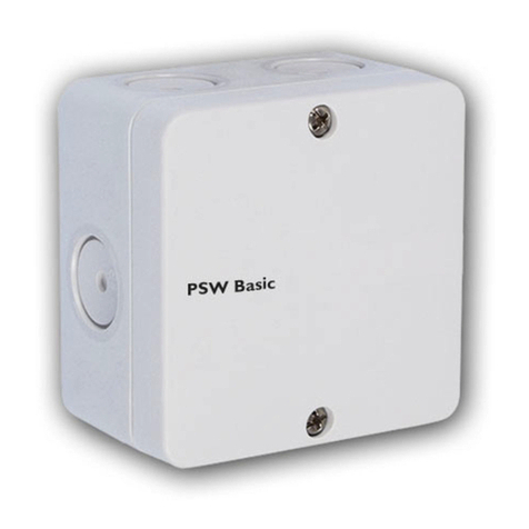
Resol PSW Basic User manual

de
2
Vielen Dank für den Kauf dieses RESOL-Gerätes.
Bitte lesen Sie diese Anleitung sorgfältig durch, um die Leistungsfähigkeit dieses
Gerätes optimal nutzen zu können. Bitte bewahren Sie diese Anleitung sorgfältig
auf.
Sicherheitshinweise
Bitte beachten Sie diese Sicherheitshinweise genau, um Gefahren und Schäden für
Menschen und Sachwerte auszuschließen.
Gefahr durch elektrischen Schlag:
• Bei Arbeiten muss das Gerät zunächst vom Netz getrennt werden.
• Das Gerät muss jederzeit vom Netz getrennt werden können.
• Das Gerät nicht in Betrieb nehmen, wenn sichtbare Beschädigungen bestehen.
Das Gerät darf nicht von Kindern oder von Personen mit reduzierten körperli-
chen, sinnlichen oder geistigen Fähigkeiten oder ohne Erfahrung und Wissen ver-
wendet werden. Sicherstellen, dass Kinder nicht mit dem Gerät spielen!
Vor Inbetriebnahme sicherstellen, dass das Gehäuse ordnungsgemäß verschlossen
ist.
Zielgruppe
Diese Anleitung richtet sich ausschließlich an autorisierte Fachkräfte.
Elektroarbeiten dürfen nur von Elektrofachkräften durchgeführt werden.
Die erstmalige Inbetriebnahme hat durch autorisierte Fachkräfte zu erfolgen.
Autorisierte Fachkräfte sind Personen, die über theoretisches Wissen und Erfah-
rungen mit Installation,Inbetriebnahme,Betrieb,Wartung etc.elektrischer/elektro-
nischer Geräte und hydraulischer Systeme sowie über Kenntnis von einschlägigen
Normen und Richtlinien verfügen.
Vorschriften
Beachten Sie bei Arbeiten die jeweiligen, gültigen Normen,Vorschriften und Richtli-
nien!
Angaben zum Gerät
BestimmungsgemäßeVerwendung
Das Gerät ist für den Einsatz in thermischen Heizungs- und Solarsystemen un-
ter Berücksichtigung der in dieser Anleitung angegebenen technischen Daten be-
stimmt.
JedeVerwendung darüber hinaus gilt als bestimmungswidrig.
Zur bestimmungsgemäßen Verwendung zählt die Einhaltung der Vorgaben dieser
Anleitung.
Die bestimmungswidrige Verwendung führt zum Ausschluss jeglicher Haftungs-
ansprüche.
Hinweis
Starke elektromagnetische Felder können die Funktion des Geräts beein-
trächtigen.
ÎSicherstellen, dass Gerät und System keinen starken elektromagneti-
schen Strahlungsquellen ausgesetzt sind.
EU-Konformitätserklärung
Das Produkt entspricht den relevanten Richtlinien und ist daher mit
der CE-Kennzeichnung versehen.Die Konformitätserklärung kann beim
Hersteller angefordert werden.
Lieferumfang
Der Lieferumfang dieses Produktes ist auf dem Verpackungsaufkleber aufgeführt.
Lagerung undTransport
Das Produkt bei einer Umgebungstemperatur von -20 … +60 °C und in trockenen
Innenräumen lagern.
Das Produkt nur in der Originalverpackung transportieren.
Reinigung
Das Produkt mit einem trockenenTuch reinigen. Keine aggressiven Reinigungsmit-
tel verwenden.
© 20211216_11207071_PSW_Basic.mon5s.indd
Irrtum und technische Änderungen vorbehalten.

de
3
Außerbetriebnahme
1. Das Gerät von der Spannungsversorgung trennen.
2. Das Gerät demontieren.
Entsorgung
• Verpackungsmaterial des Gerätes umweltgerecht entsorgen.
• Am Ende seiner Nutzzeit darf das Produkt nicht zusammen mit dem Siedlungs-
abfall beseitigt werden.Altgeräte müssen durch eine autorisierte Stelle umwelt-
gerecht entsorgt werden.Auf Wunsch nehmen wir Ihre bei uns gekauften Altge-
räte zurück und garantieren für eine umweltgerechte Entsorgung.
Symbolerklärung
Warnhinweise sind mit einemWarnsymbol gekennzeichnet!
Signalwörter kennzeichnen die Schwere der Gefahr, die auftritt, wenn sie nicht
vermieden wird.
WARNUNG bedeutet, dass Personenschäden, unter Umständen auch
lebensgefährlicheVerletzungen auftreten können.
ÎEs wird angegeben, wie die Gefahr vermieden werden kann!
ACHTUNG bedeutet, dass Sachschäden auftreten können.
ÎEs wird angegeben, wie die Gefahr vermieden werden kann!
Hinweis
Hinweise sind mit einem Informationssymbol gekennzeichnet.
ÎTextabschnitte, die mit einem Pfeil gekennzeichnet sind, fordern zu einer
Handlung auf.
1. Textabschnitte, die mit Ziffern gekennzeichnet sind, fordern zu mehreren auf-
einanderfolgenden Handlungsschritten auf.

de
4
Inhalt
1 Übersicht ............................................................................................ 5
2 Installation .......................................................................................... 6
2.1 Montage ........................................................................................................................6
2.2 Elektrischer Anschluss ...............................................................................................6
2.3 Invertierung des Ausgangssignals.............................................................................7
2.4 Anwendungsbeispiel (Pumpe mit PWM-Ansteuerung)......................................7
3 Zubehör .............................................................................................. 7

de
5
Technische Daten
Eingänge: Ein/Aus, Pulspakete/ Wellenpakete, Phasenanschnitt, Phasenabschnitt
Ausgänge: PWM/0-10V
PWM-Frequenz: 625 Hz ±15 %
PWM-Spannung: 11V
Versorgung: 230 V~ (50 Hz)
Anschlussart: X
Leistungsaufnahme: max. 1,5VA
Wirkungsweise: 1
Bemessungsstoßspannung: 2,5kV
Funktionen: Signalwandler, Umwandlung eines drehzahlgeregelten 230-V-Aus-
gangssignals in ein PWM- oder 0-10-V-Signal
Gehäuse: Kunststoff, PC-ABS und PMMA
Montage: Wandmontage
Schutzart: IP65 / DIN EN 60529
Schutzklasse: II
Umgebungstemperatur: 0 … 40 °C
Verschmutzungsgrad: 2
Luftfeuchtigkeit: 10 … 90 %
Überspannungskategorie: 2
Sicherung: T0,2A
Maximale Höhenlage: 2000 m NN
Maße: 80 x 80 x 53 mm
Maße und Mindestabstände
80 mm
90 mm
50 mm
150 mm
80 mm
120 mm
20 mm
20 mm
50 mm
90 mm
Position der Bohrlöcher
1 Übersicht
Der Signalwandler PSW Basic erlaubt den Anschluss drehzahlgeregelter Hochef-
zienzpumpen mit PWM- oder 0-10-V-Steuereingang an Regler ohne entsprechen-
den Ausgang.
• Für Solar- und Heizungspumpen
• Ausgangssignal PWM oder 0-10V
• Invertierung des Ausgangssignals möglich
• Solide, spritzwassergeschützte Ausführung
Der Pumpensignalwander PSW Basic wandelt das 230-V-Signal vom Regler, an
dem zuvor eine Standardpumpe angeschlossen war, in ein Signal um, mit dem
eine HE-Pumpe drehzahlgeregelt angesteuert werden kann. Pro Signalwandler 1
HE-Pumpe anschließbar.
Folgende Signalumwandlungen sind möglich:
Ausgangssignal
Eingangssignal
PWM PWM
neg.
0-10V 0-10V
neg.
Ein/Aus xxxx
Pulspaket x x x x
Phasenanschnitt x x x x
Phasenabschnitt x x x x
Nicht geeignet für Wärmepumpen und Frischwasserregler

de
6
2 Installation
2.1 Montage
80
50
80
80
90
WARNUNG! Elektrischer Schlag!
Bei geöffnetem Gehäuse liegen stromführende Teile frei!
ÎVor jedem Öffnen des Gehäuses das Gerät allpolig
von der Netzspannung trennen!
Hinweis
ÎDas Gerät ausschließlich ortsfest montieren. Auf ausreichende Zugent-
lastung der Leitungen achten.
Das Gerät ausschließlich in trockenen Innenräumen montieren. Für eine einwandfreie
Funktion an dem ausgewählten Ort das Gerät keinen starken elektromagnetischen Feld-
ern aussetzten.
Falls das Gerät nicht mit einer Netzanschlussleitung und einem Stecker ausgerüstet
ist, muss das Gerät über eine zusätzliche Einrichtung mit einer Trennstrecke von min-
destens 3 mm allpolig bzw. mit einer Trennvorrichtung (Sicherung) nach den geltenden
Installationsregeln vom Netz getrennt werden können.
Bei der Installation der Netzanschlussleitung und der Signalleitungen auf getrennteVer-
legung achten.
Um das Gerät an der Wand zu montieren, folgende Schritte durchführen:
1. Die Position für die Montage auswählen und Bohrlöcher durch die Laschen markieren.
2. Beide Löcher bohren und vorbereiten.
3. Das Gehäuse durch die Laschen festschrauben.
4. Beide Schrauben lösen.
5. Das Gehäuseoberteil abnehmen.
6. Den elektrischen Anschluss vornehmen.
7. Das Gehäuseoberteil wieder aufsetzen und mit den beiden Schrauben xieren.
2.2 Elektrischer Anschluss
WARNUNG! Elektrischer Schlag!
Bei geöffnetem Gehäuse liegen stromführende Bauteile frei!
ÎVor jedem Öffnen des Gehäuses das Gerät allpolig
von der Netzspannung trennen!
ACHTUNG! Elektrostatische Entladung!
Elektrostatische Entladung kann zur Schädigung elektronischer
Bauteile führen!
ÎVor dem Berühren für Entladung sorgen!
Hinweis
Starke elektromagnetische Felder können die Funktion des Gerätes beein-
trächtigen.
ÎSicherstellen, dass Gerät und System keinen starken elektromagne-
tischen Strahlungsquellen ausgesetzt sind.
Hinweis
Das Gerät muss jederzeit vom Netz getrennt werden können.
ÎDen Netzstecker so anbringen, dass er jederzeit zugänglich ist.
ÎIst dies nicht möglich, einen jederzeit zugänglichen Schalter installieren.
Wenn die Netzanschlussleitung beschädigt wird, muss sie durch eine beson-
dere Anschlussleitung ersetzt werden, die beim Hersteller oder seinem Kun-
dendienst erhältlich ist.
Das Gerät nicht in Betrieb nehmen, wenn sichtbare Beschädigungen bestehen!
Der Anschluss des Gerätes an die Netzspannung ist immer der letzte Arbeitsschritt!
Die Stromversorgung des Gerätes erfolgt über eine Netzleitung. DieVersorgungs-
spannung muss 230V~ (50 Hz) betragen.
Die Signalleitung vom Regler an den Niederspannungseingang des Gerätes anschließen:
R In N max. 240 V = Neutralleiter N vom Regler
R In L max. 240 V= 230-V-Steuersignal vom Regler (Leiter L)

de
7
ACHTUNG! Funktionsstörung!
Bei Pumpen mit Leitungsbruchdetektion läuft die Pumpe im Mini-
malbetrieb, wenn das Steuersignal 0V beträgt.
ÎKeine Pumpen mit Leitungsbruchdetektion mit ei-
nem 0-10-V-Steuersignal betreiben!
Den blauen Leiter der Signalleitung der Pumpe an GND anschließen.Den braunen
Leiter je nach Signaltyp an eine der folgenden Klemmen anschließen:
0-10V Out = 0-10-V-Steuersignal für HE-Pumpe
PWM Out = PWM-Steuersignal für HE-Pumpe
Der Netzanschluss des Gerätes ist an den folgenden Klemmen:
N= Neutralleiter N
L= Leiter L
Die Spannungsversorgung der Pumpe muss extern erfolgen (230 V~).
GND
0-10V
Out
PWM
Out
T0,2A
230 V~,
50 Hz
R In L
max 240V
R In N
max 240V
PSW Basic
LN
S H
Heiskampstraße 10
DE-45527 Hattingen
2.3 Invertierung des Ausgangssignals
Über den dreipoligen Jumper links oberhalb der Ausgangsklemmen kann eingestellt
werden, ob das Ausgangssignal invertiert oder nicht invertiert ausgegeben wird.
Jumperstellung links: nicht invertiert (Solarpumpe)
Jumperstellung rechts: invertiert (Heizungspumpe)
Eingang
100%
Ausgang
PWM
0-10V
Solar (S)
Heizung (H)
0% 100%
S H
2.4 Anwendungsbeispiel (Pumpe mit PWM-Ansteuerung)
X
GND
0-10V
Out
PWM
Out
T0,2A
230V~,
50 Hz
R In L
max 240 V
R In N
max 240 V
LN
S H
IP 20
T4A
100 – 240V~
50 – 60 Hz
Temp. Sensor Pt1000
S1 S2 S3 S4 R1VBus
1 2 3 4 5 6 7 8 9 10 12 13 14 17 18 19 20
N N L
1 (1) A 100 –240 V~
PSW Basic
Heiskampstraße 10
DE-45527 Hattingen
blau braun
braun
gelb/grün
blau
Spannungsversorgung 230V~/Netzanschluss
230V~ /Netzanschluss
schwarz (nicht
verwendet)
Signalleitung
PWM
Signaleingang
Pumpe Spannungsversorgung
Pumpe
Eingangssignal:
230-V-Steuersignal vom Regler
(Ein/Aus, Pulspaket/Wellenpaket, Phasenanschnitt, Phasenabschnitt)
Anschluss am Beispiel eines DeltaSol®BS
3 Zubehör
HE-Check –Testgerät für PWM- und 0-10-V-Signale
Mit dem HE-Check können die Funktion der Pumpe und die
Signale des Reglers schnell und einfach überprüft werden.

Ihr Fachhändler: RESOL–Elektronische Regelungen GmbH
Heiskampstraße 10
45527 Hattingen/Germany
Tel.: +49 (0) 23 24 / 96 48 - 0
Fax: +49(0)2324/9648-755
www.resol.de
Wichtiger Hinweis
Die Texte und Zeichnungen dieser Anleitung entstanden mit größtmöglicher Sorg-
falt und nach bestem Wissen. Da Fehler nie auszuschließen sind, möchten wir auf
folgendes hinweisen:
Grundlage Ihrer Projekte sollten ausschließlich eigene Berechnungen und Planun-
gen an Hand der jeweiligen gültigen Normen und Vorschriften sein.Wir schließen
jegliche Gewähr für die Vollständigkeit aller in dieser Anleitung veröffentlichten
Zeichnungen und Texte aus, sie haben lediglich Beispielcharakter. Werden darin
vermittelte Inhalte benutzt oder angewendet, so geschieht dies ausdrücklich auf
das eigene Risiko des jeweiligen Anwenders. Eine Haftung des Herausgebers für
unsachgemäße, unvollständige oder falsche Angaben und alle daraus eventuell ent-
stehenden Schäden wird grundsätzlich ausgeschlossen.
Anmerkungen
Das Design und die Spezikationen können ohne Vorankündigung geändert werden.
Die Abbildungen können sich geringfügig vom Produktionsmodell unterscheiden.
Impressum
Diese Montage- und Bedienungsanleitung einschließlich aller seiner Teile ist urhe-
berrechtlich geschützt. Eine Verwendung außerhalb des Urheberrechts bedarf der
Zustimmung der Firma RESOL–Elektronische Regelungen GmbH. Dies gilt insbe-
sondere für Vervielfältigungen / Kopien, Übersetzungen, Mikroverlmungen und die
Einspeicherung in elektronischen Systemen.
©RESOL–Elektronische Regelungen GmbH

PSW Basic
www.resol.com
Manual
Pump signal converter
en

en
10
Thank you for buying this RESOL product.
Please read this manual carefully to get the best performance from this unit.
Please keep this manual safe.
Safety advice
Please pay attention to the following safety advice in order to avoid danger and
damage to people and property.
Danger of electric shock:
• When carrying out works, the device must rst of all be disconnected from
the mains.
• It must be possible to disconnect the device from the mains at any time.
• Do not use the device if it is visibly damaged!
The device must not be used by children or persons with reduced physical, sen-
sory or mental abilities or without any experience and knowledge. Make sure that
children do not play with the device!
Make sure that the housing is properly closed before commissioning the device.
Target group
These instructions are exclusively addressed to authorised skilled personnel.
Only qualied electricians are allowed to carry out electrical works.
Initial commissioning must be effected by authorised skilled personnel.
Authorised skilled personnel are persons who have theoretical knowledge and
experience with the installation, commissioning, operation, maintenance, etc. of
electric/electronic devices and hydraulic systems and who have knowledge of rel-
evant standards and directives.
Instructions
Attention must be paid to the valid local standards, regulations and directives!
Information about the product
Proper usage
The device is designed for use in standard solar thermal systems and heating sys-
tems in compliance with the technical data specied in this manual.
Any use beyond this is considered improper.
Proper usage also includes compliance with the specications given in this manual.
Improper use excludes all liability claims.
Note
Strong electromagnetic elds can impair the function of the device.
ÎMake sure the device as well as the system are not exposed to strong
electromagnetic elds.
EU Declaration of conformity
The product complies with the relevant directives and is therefore la-
belled with the CE mark. The Declaration of Conformity is available
upon request, please contact the manufacturer.
Scope of delivery
The scope of delivery of this product is indicated on the packaging label.
Storage and transport
Store the product at an ambient temperature of -20…+60°C and in dry interior
rooms only.
Transport the product in its original packaging only.
Cleaning
Clean the product with a dry cloth. Do not use aggressive cleaning uids.
Decommissioning
1. Disconnect the device from the power supply.
2. Dismount the device.
© 20211216_11207071_PSW_Basic.mon5s.indd
Subject to technical change. Errors excepted.

en
11
Disposal
• Dispose of the packaging in an environmentally sound manner.
• At the end of its working life, the product must not be disposed of as urban
waste. Old appliances must be disposed of by an authorised body in an environ-
mentally sound manner. Upon request we will take back your old appliances
bought from us and guarantee an environmentally sound disposal of the devices.
Description of symbols
Warnings are indicated with a warning symbol!
Signal words describe the danger that may occur, when it is not avoided.
WARNING means that injury, possibly life-threatening injury, can oc-
cur.
ÎIt is indicated how to avoid the danger described.
ATTENTION means that damage to the appliance can occur.
ÎIt is indicated how to avoid the danger described.
Note
Notes are indicated with an information symbol.
ÎTexts marked with an arrow indicate one single instruction step to be carried
out.
1. Texts marked with numbers indicate several successive instruction steps to be
carried out.

en
12
Inhalt
1 Overview........................................................................................... 13
2 Installation ........................................................................................ 14
2.1 Mounting.................................................................................................................... 14
2.2 Electrical connection............................................................................................... 14
2.3 Inverting the output signal..................................................................................... 15
2.4 Application examples (pump with PWM control)........................................... 15
3 Accessories ....................................................................................... 15

en
13
Technical data
Inputs: On/Off, bursts / wave packets, phase cutting
Outputs: PWM/0-10V
PWM frequency: 625 Hz ±15%
PWM voltage: 11V
Power supply: 230V~ (50 Hz)
Supply connection: type X attachment
Power consumption: max. 1.5VA
Mode of operation: 1
Rated impulse voltage: 2,5kV
Functions: signal converter, converting a speed-controlled 230 V signal into a
PWM or 0-10V signal
Housing: plastic, PC-ABS and PMMA
Mounting: wall mounting
Ingress protection: IP65 / EN 60529
Protection class: II
Ambient temperature: 0… 40 °C
Degree of pollution: 2
Humidity: 10…90%
Overvoltage category: 2
Fuse: T0.2A
Maximum altitude: 2000 m above MSL
Dimensions: 80 x 80 x 53 mm
Dimensions and minimum distances
80 mm
90 mm
50 mm
150 mm
80 mm
120 mm
20 mm
20 mm
50 mm
90 mm
Drill hole positions
1 Overview
The PSW Basic signal converter is used for connecting speed-controlled high-ef-
ciency pumps with a PWM or 0-10 V control input to a controller without a
corresponding output.
• For solar and heating pumps
• PWM or 0-10V output signal
• Inversion of the output signal possible
• Robust and dripping water protected housing
The PSW Basic pump signal converter converts the 230V signal of the controller
to which a standard pump had previously been connected,into a signal that enables
speed control of a HE pump. 1 HE pump per signal converter connectable.
The following signal conversions are possible:
Input signal
Output signal
PWM PWM
inv.
0-10V 0-10V
inv.
On/Off xxxx
Burst/wave packet xxxx
Leading-edge phase control x x x x
Trailing-edge phase control x x x x
Not suitable for heat pumps and DHW exchange controllers

en
14
2 Installation
2.1 Mounting
80
50
80
80
90
WARNING! Electric shock!
Upon opening the housing, live parts are exposed!
ÎAlways disconnect the device from power supply be-
fore opening the housing!
Note
ÎThe device is suited for stationary mounting only. Pay attention to
strain relief when routing the cables.
The unit must only be located in dry interior rooms. It is not suitable for installa-
tion in hazardous locations and should be protected against electromagnetic elds.
If the device is not equipped with a mains connection cable and a plug, the device
must additionally be supplied from a double pole switch with contact gap of at
least 3 mm.
Please pay attention to separate routing of sensor cables and mains cables.
In order to mount the device to the wall, carry out the following steps:
1. Determine the mounting site and mark the holes through the fastening points.
2. Drill holes and insert the wall plugs.
3. Fasten the housing.
4. Unscrew both screws.
5. Remove the upper part of the housing.
6. Carry out the electrical connection.
7. Attach the upper part to the housing and tigthen both screws.
2.2 Electrical connection
WARNING! Electric shock!
Upon opening the housing, live parts are exposed!
ÎAlways disconnect the device from power supply
before opening the housing!
ATTENTION! ESD damage!
Electrostatic discharge can lead to damage to electronic com-
ponents!
ÎTake care to discharge properly before touching
the inside of the device!
Note:
Strong electromagnetic elds can impair the function of the device.
ÎMake sure the device as well as the system are not exposed to strong
electromagnetic elds.
Note:
It must be possible to disconnect the device from the mains at any time.
ÎInstall the mains plug so that it is accessible at any time.
ÎIf this is not possible, install a switch that can be accessed.
If the mains cable is damaged, it must be replaced by a special connection
cable which is available from the manufacturer or its customer service.
Do not use the device if it is visibly damaged!
Connecting the device to the power supply must always be the last step of the
installation!
The device is supplied with power via a mains cable.The supply voltage must be
230V~ (50Hz).
Connect the signal cable from the controller to the low voltage input of the device:
R In N max. 240 V = neutral conductor N from the controller
R In L max. 240 V = 230V control signal from the controller (conductor L)

en
15
ATTENTION! Malfunction!
Pumps with line break detection run with minimum speed if
the control signal is 0V.
ÎDo not operate pumps with line break detection
by a 0-10V signal!
Connect the blue wire of the signal cable of the pump to GND.Depending on the
signal type, connect the brown wire to one of the following terminals:
0-10V Out = 0-10V control signal for the HE pump
PWM Out = PWM control signal for the HE pump
The mains connection of the device is at the following terminals:
N= neutral conductor N
L= conductor L
The pump must be supplied by an external power source (230V~).
Seriennummer
GND
0-10V
Out
PWM
Out
T0,2A
220 ... 240 V~,
50-60 Hz
R In L
max 240V
R In N
max 240V
PSW Basic
LN
S H
Made in Germany
2.3 Inverting the output signal
By means of the three-pole jumper on the left-hand side above the output termi-
nals the output signal can be issued inverted or not inverted.
Jumper position left: not inverted (solar pump)
Jumper position right: inverted (heating pump)
Input
100%
Output
PWM
0-10V
Solar (S)
Heating (H)
0% 100%
S H
2.4 Application examples (pump with PWM control)
X
GND
0-10V
Out
PWM
Out
T0,2A
230V~,
50 Hz
R In L
max 240 V
R In N
max 240 V
LN
S H
IP 20
T4A
100 – 240V~
50 – 60 Hz
Temp. Sensor Pt1000
S1 S2 S3 S4 R1VBus
1 2 3 4 5 6 7 8 9 10 12 13 14 17 18 19 20
N N L
1 (1) A 100 –240 V~
PSW Basic
Heiskampstraße 10
DE-45527 Hattingen
blue brown
brown
yellow/green
blue
Power supply 230 V~ /Mains connection
230V~ /Mains connection
black (not used)
Signal cable
PWM
Signal input
Pump
Power supply pump
Input signal:
230V control signal from the controller (On /Off, burst / wave
packet, leading-edge phase cutting, trailing-edge phase cutting)
Example: connection to a DeltaSol®BS controller
3 Accessories
HE-Check –Testing device for PWM- and 0-10V signals
With the HE-Check, the function of the pump and the sig-
nals of the controller can be checked quickly and easily.

Distributed by: RESOL – Elektronische Regelungen GmbH
Heiskampstraße 10
45527 Hattingen / Germany
Tel.: +49 (0) 23 24 / 96 48 - 0
Fax: +49(0)2324/9648-755
www.resol.com
Important note
The texts and drawings in this manual are correct to the best of our knowledge.As
faults can never be excluded, please note:
Your own calculations and plans, under consideration of the current standards and
directions should only be basis for your projects.We do not offer a guarantee for
the completeness of the drawings and texts of this manual - they only represent
some examples.They can only be used at your own risk. No liability is assumed for
incorrect, incomplete or false information and / or the resulting damages.
Note
The design and the specications can be changed without notice.
The illustrations may differ from the original product.
Imprint
This mounting and operation manual including all parts is copyrighted.Any other
use outside the copyright requires the approval of RESOL – Elektronische Rege-
lungen GmbH. This especially applies to copies, translations, micro lms and the
storage into electronic systems.
©RESOL–Elektronische Regelungen GmbH

PSW Basic
www.resol.com
Manuel
Convertisseur de signal
fr

fr
18
© 20211216_11207071_PSW_Basic.mon5s.indd
Merci d’avoir acheté ce produit RESOL.
Veuillez lire le présent mode d’emploi attentivement an de pouvoir utiliser
l’appareil de manière optimale.Veuillez conserver ce mode d’emploi.
Recommandations de sécurité
Veuillez lire attentivement les recommandations de sécurité suivantes an d’éviter
tout dommage aux personnes et aux biens.
Risque de choc électrique :
• Avant toute intervention, l’appareil doit être débranché du réseau électrique.
• L’appareil doit pouvoir être débranché du réseau électrique à tout moment.
• N’utilisez pas l’appareil en cas d’endommagement visible !
L’appareil ne doit pas être utilisé par des enfants ou des personnes aux capacités
physiques, sensorielles ou mentales diminuées, voire manquant d’expérience et de
connaissance.Veillez à ce que les enfants ne jouent pas avec l’appareil !
Avant la mise en service, le boîtier de l’appareil doit être fermé correctement !
Groupe cible
Ce manuel d‘instructions vise exclusivement les techniciens habilités.
Toute opération électrotechnique doit être effectuée par un technicien en élec-
trotechnique.
La première mise en service doit être effectuée par un technicien qualié.
Les techniciens qualiés sont des personnes qui ont des connaissances théoriques
et une expérience dans le domaine de l’installation, de la mise en service, du fonc-
tionnement, de la maintenance, etc. des appareils électriques/électroniques et sys-
tèmes hydrauliques et qui connaissent les normes et directives concernées en
vigueur.
Instructions
Lors des travaux, veuillez respecter les normes, réglementations et directives en
vigueur!
Informations concernant l’appareil
Utilisation conforme
L'appareil est conçu pour l'utilisation dans des installations de chauffage solaire
thermique et conventionnel en tenant compte des données techniques énoncées
dans le présent manuel.
Toute utilisation en dehors de ce cadre est considérée comme non-conforme.
Une utilisation conforme comprend le respect des spécications de ce manuel.
Toute utilisation non conforme entraînera une exclusion de garantie.
Note :
Des champs électromagnétiques trop élevés peuvent perturber le fonc-
tionnement de l‘appareil.
ÎVeillez à ne pas exposer ce dernier ni le système à des champs élec-
tromagnétiques trop élevés.
Déclaration UE de conformité
Le marquage CE est apposé sur le produit, celui-ci étant conforme aux
dispositions communautaires prévoyant son apposition. La déclaration
de conformité est disponible auprès du fabricant sur demande.
Fournitures
Les fournitures de ce produit sont indiquées sur l’étiquette d’emballage.
Stockage et transport
Stockez le produit à une température comprise entre -20 … +60 °C et dans une
pièce intérieure sèche.
Transportez le produit uniquement dans son emballage original.
Nettoyage
Nettoyez le produit avec un chiffon sec. N‘utilisez pas de produits de nettoyage
agressifs.
Mise hors service
1. Débranchez l’appareil de l’alimentation électrique.
2. Démontez l’appareil.
Sous réserve d’erreurs et de modications techniques.

fr
19
Traitement des déchets
• Veuillez recycler l’emballage de l‘appareil.
• L‘appareil en n de vie ne doit pas être jeté dans les déchets ménagers. Les
appareils en n de vie doivent être déposés auprès d’une déchetterie ou d’une
collecte spéciale de déchets d’équipements électriques et électroniques.Sur de-
mande, nous reprenons les appareils usagés que vous avez achetés chez nous en
garantissant une élimination respectueuse de l’environnement.
Explication des symboles
Les avertissements de sécurité sont précédés d’un symbole de signali-
sation !
Les mots d’alerte caractérisent la gravité du danger qui survient si celui-ci n’est
pas évité.
AVERTISSEMENT indique que de graves dommages corporels, voir
même un danger de mort, peuvent survenir.
ÎIl est indiqué comment éviter le danger !
ATTENTION indique que des dommages aux biens peuvent sur-
venir.
ÎIl est indiqué comment éviter le danger !
Note
Toute information importante communiquée à l‘utilisateur est précédée
de ce symbole.
ÎLes parties de texte marquées d’une èche appellent à une action.
1. Les textes précédés de chiffres appellent plusieurs actions successives.

fr
20
Contenu
1 Vue d‘ensemble ................................................................................ 21
2 Installation ........................................................................................ 22
2.1 Montage ..................................................................................................................... 22
2.2 Raccordement électrique....................................................................................... 22
2.3 Inversion du signal de sortie ................................................................................. 23
2.4 Exemple d’application (pompe à commande PWM)........................................ 23
3 Accessoires ....................................................................................... 23
Other manuals for PSW Basic
4
Table of contents
Languages:
Other Resol Media Converter manuals

Resol
Resol PSW Universal User manual

Resol
Resol PSW Premium Pump User manual

Resol
Resol PSW Basic User manual

Resol
Resol PSW Basic User manual

Resol
Resol PSW Premium Pump User manual

Resol
Resol PSW Basic User manual

Resol
Resol PSW Basic User manual

Resol
Resol PSW Premium Pump User manual

Resol
Resol PSW Premium Pump User manual