EXIDY CRASH User manual

July
1979
(c)
197
9
EXIDY,
Inc.

I l
j

CONTENTS
I.
GENERAL
3
II.
NORMAL
OPERATION
A.
Attract
Mode . . . . . . • . . . . . . . . . . . . . • . . . . . . • . . . • . 4
B.
Introduction
Mode
•..........•..•........•....
4
C.
Game
Play
•.•.•..•.•..•.............••........
4
III.
SELECTABLE OPTIONS
A.
Coinage
. . . . . . . . . . . . . . . . . . . . . . . . . . . . . . . . . . . . . . 5
B.
Crashes
(Turns)
.•.•.•...•.........•..••.•....
5
C.
TOP
THIS
SCORE
. . . . • . . • . . . • . . . . • . . . . . • . • . . . . . . 5
IV.
AUDIO
ADJUSTMENTS
5
V.
POWER
SUPPLY
ADJUSTMENTS
6
VI.
MECHANICAL
ASSEMBLIES
A.
To
Service
Early-Production
Control
Panels
... 7
B.
To
Service
Late-Production
Control
Panels
.... 8
c.
To
Service
the
Four-Way
Joy
Stick
............
9
D. To
Remove
the
Monitor
........................
10
E.
To
Remove
the
Logic
and
Audio
Boards
.
........
10
VII.
TECHNICAL INFORMATION
A.
Logic
Description
and
Operation
•.........••..
11
B.
Audio
Description
and
Operation
•.•.•...•.....
11
C.
Diagrams,
Pinout
Table,
and
Schematics
•......
14
1

ILLUSTRATIONS
Figure
1 :
Monitor
Display
.......................... 3
Figure
2:
Audio
Board
Adjustments
.................. 5
Figure
3:
Power
Supply
Adjustments
................. 6
Figure
4:
Control
Panel
(Early
Production)
.....•.•.
. 7
Figure
5:
Control
Panel
(Late
Production)
.......... 8
Figure
6:
Four-Way
Joy
Stick
....................... 9
Figure
7:
Major
Internal
Components
................
10
Figure
8:
Logic
Board
Block
Diagram
................
14
Figure
9:
Audio
Board
Block
Diagram
................
15
Figure
1
0:
Harness
Diagram
..........................
16
2

I.
GENERAL
CRASH
is
a
one
or
two
player
skill
game
in
which
players
drive
a
car
around
a
five
lane
square
track
while
avoiding
collisions
with
com-
puter
controlled
drone
cars.
Play-
ers
score
points
by
driving
over
speed
·
dots
marked
on
the
traffic
lanes;
players
avoid
collisions
by
changing
lanes
at
the
four
traffic
interchanges,
and
by
using
the
FAST
button
to
beat
drone
cars
to
inter-
changes.
1
• • • • • •
• • • • • •
• • • • • •
• • • • • •
2
CRASH
has
three
coinage
options.
After
the
player
inserts
his
coins,
play
instructions
and
the
day's
high
score
appear
on
screen.
An
optional
TOP
THIS
SCORE
feature
gives
a
replay
to
the
player
who
beats
a
random
score.
The
operator
selects
the
number
of
crashes
(turns)
per
play:
2,
3,
4,
or
5.
3
• • • • •
• • • • • •
• • • • • •
• • • • • •
• • • •
~~
• • • •
• • • •
AVER
#1
• • • • •
RIVING
• • • • • • • • • •
6
illiE
• • • • • • • • • •
• • • • •
#1
0 • • • • •
• • • • • • • • • • • •
• • • • • • • • • • • •
• • • • • • • • • • • •
• • • • • • • • • • • •
• • • • • iii • •
Monitor
Display
5 4
1
Traffic
lane
4
Player
car
2
Interchange
5
Drone
car
3
Speed
dot
6
Message
panel
3

II.
NORMAL
OPERATION
A.
Attract
Mode
When
the
game
is
first
turned
on,
the
words
GAME
OVER
will
flash
on
screen.
Also
on
screen
will
be
TODAY'S HIGH SCORE
followed
by
a
score
which
changes
with
each
new
higher
score
attained
throughout
the
day.
When
the
game
is
turned
off,
the
high
score
is
reset
to
zero.
Also
displayed
on
screen,
at
the
operatorts
selection,
will
be
one
of
the
following:
COIN
PLAY
2 • • • • • • • • • • • • • • • • • 1
COIN
1
2
COIN
2
or
PLAY
• • • • • • • • • • • • • • • • • 1
• • • . • • • • • • • • • • • • • 2
or
PLAY
• • • • • • • • • • • • • • • • • 1
4
•••••••••••••••
·
••
2
CRASH
also
has
a
coin
accumulator
(credit
counter)
so
that
.·a
player
can
buy
a
number
of
games
in
ad-
vance.
While
in
the
attract
mode
(no
cred-
its,
no
game
iri
progress)
the
game
plays
automatically.
B.
Introduction
Mode
When a
player
deposits
a
cpin,
the
following
message
comes
on
screen:
4
CHANGE
LANES
TO
AVOID
CRASH
WITH
OTHER
CARS
10
POINTS FOR
EACH
DOT
BONUS
POINTS
IF
ALL
DOTS
ARE
ELIMINATED
CREDITS N
TOP
THIS
SCORE
FOR CREDIT
M
Here,
N
is
the
number
of
games
in
the
credit
counter,
and
M
is
a
.
random
score
used
by
the
TOP
THIS
SCORE
feature.
At
the
operator's
option,
CRASH
awards
one
extra
game
to
any
player
who
matches
or
ex-
ceeds
the
score
M.
C.
Game
Play
When a
player
presses
one
of
the
two
START
buttons
(after
coinage),
a
fanfare
tune
signals
the
start
of
play.
The
player's
car
starts
at
the
bottom
center
of
the
screen
(in
the
outer
lane)
and
moves
counter-
clockwise.
One
drone
car
starts
at
the
same
place,
moving
in
the
oppo-
site
direction.
The
drone
car
tries
to
crash
into
the
player's
car.
The
player
must
avoid
crashes
by
changing
lanes
at
interchanges;
he
uses
the
FAST
but-
ton
to
reach
an
interchange
before
the
drone
car.
When
the
player's
car
drives
over
a
speed
dot,
the
SPEED BEEP
sounds
and
the
dot
disappears.
At
game
start,
each
dot
scores
10
points;
if
the
player
clears
all
the
dots
in
a
single
turn
(without
crashing
into
the
drone
car)
the
playf
ield
is
reset,
and
all
speed
dots
score
20
points.
Each
successive
time
the
player
clears
all
dots,
the
dot
score
goes
up:
20
points,
30
points,
etc.
The
number
of
drone
cars
increases
with
the
point
value
of
the
speed
dots.
At
game
start
(10
points
per
dot)
only
one
drone
opposes
the
player;
at
the
next
level
(20
points
per
dot)
two
drones
oppose
him.
At
all
succeeding
levels
{30
points
and
above),
three
drones.
A
turn
continues
until
the
player
crashes
into
a
drone
car.
The
mes-
sage
display
in
the
center
of
the
screen
shows
turns
remaining,
by
displaying
one
car
for
each
crash
(turn)
left,
not
counting
the
cur-
rent
turn.

III.
SELECTABLE OPTIONS
CRASH
has
three
switch
selectable
options.
These
are
controlled
by
a
seven
segment
DIP
switch
located
on
the
main
logic
board
at
position
14A
(see
Figure
2,
item
6).
This
switch
is
acccessible
from
the
front
of
the
game
though
the
coin
door.
Following
are
the
options
and
the
switch
settings
for
their
selec-
tion:
A.
Coinage
switch
switch
4 5
2
Player
-1
Coin
ON ON
1
Player
-1
Coin
ON
OFF
2
Player
-2
Coin
1
Player
-2
Coin
OFF
ON
2
Player
-4
Coin
B.
Crashes
(Turns)
switch
switch
6 7
2
Crashes
ON ON
3
Crashes
ON
OFF
4
Crashes
OFF
ON
5
Crashes
"'
OFF OFF
c.
TOP
THIS
SCORE
switch
3
Credit
awarded
for
OFF
topping
score
Credit
not
awarded
ON
for
topping
score
IV.
AUDIO
ADJUSTMENTS
(Figure
2)
MOTOR
MUSIC
3
pots:
R52=high
frequency
R53=low
frequency
R16=volume
1
pot:
R63=volume
VOLUME
1
pot:
R66=overall
volume
CRASH
1
pot:
R29=volume
SPEED BEEP 1
pot:
R39=volume
SKID 2
pots:
R47=frequency
R49=volume
2
1
®
9
Figure
2:
Audio
Hoard
Adjustments
1 R52
MOTOR
6
DIP
SWITCH
2 R53
MOTOR
7 R39 SPEED BEEP
3 R63 MUSIC 8 R49 SKID
4 R66
VOLUME
9 R47 SKID
5 R29
CRASH
1 0 R16
MOTOR
5

V.
POWER
SUPPLY ADJUSTMENTS
1.
Connect
a
voltmeter
to
the
+5
and
ground
traces
on
the
logic
board.
0
0
2.
Adjust
the
power
supply
potenti-
ometer
for
+5.0
+
.1
VDC
(see
Figure
3).
Adjustment
potentiometer
Figure
3:
Power
Supply
Adjustments
6

VI.
MECHANICAL
ASSEMBLIES
NOTE
Each
CRASH
game
has
one
of
two
control
panels:
* A
single
metal
plate,
held
by
four
carriage
bolts
(early
production)
•
* A
large
metal
plate,
hinged
at
the
bottom
(late
production).
A.
To
Service
Early
Production
Control
Panels
(see
Figure
4).
1.
Unplug
power
cord.
2 3
l
4
2.
Open
the
coin
door.
3.
Reaching
up
through
the
coin
door,
remove
the
wingnuts
from
the
four
carriage
bolts
that
hold
the
control
panel
down.
4.
Lift
the
control
panel
up
from
the
cabinet
and
set
it
on
edge,
so
that
you
can
reach
its
underside.
5.
Check
all
terminal
connections
to
the
pushbuttons
and
the
four-
way
joy
stic-k.
6 6
Figure
4:
Control
Panel
(Early
Production)
1
Carriage
bolt
2
Start
buttons
3 FAST
button
4
Control
panel
5
Four-way
control
6
Control
harness
7

B.
To
Service
Late
Production
Control
Panels
(see
Figure
5)
1.
Unplug
the
power
cord.
2.
Open
and
remove
the
back
door.
3.
From
inside
the
cabinet,
remove
the
three
control
panel
nuts
(see
Figure
7)
•
\
\ \
7
4.
Open
the
coin
door.
5.
From
the
front
of
the
cabinet,
pull
the
control
panel
out
and
down;
let
it
rest
on
the
open
coin
door
(see
Figure
5).
6.
Check
all
terminal
connections
to
the
pushbuttons
and
the
four-
way
control.
Figure
5:
Control
Panel
(Late
Production)
1
Control
panel
4
Main
harness
2
Start
buttons
5
Four-way
control
3
Control
harness
6
Control
stick
7 FAST
button
8
I

C.
To
Service
the
Four-Way
Joy
Stick
The
four-way
joy
stick
is
mounted
on
the
control
panel
with
four
long
screws
and
standoff
spacers.
Four
pairs
of
spring
steel
cup
washers
surround
the
control
stick,
between
the
control
panel
and
the
top
plate
(see
Figure
6).
These
cup
washers
bear
against
a
disk
welded
to
the
control
stick,
and
push
the
stick
towards
its
center
(rest)
position.
Four
leaf
switches
on
the
bottom
plate
(activated
by
the
control
stick)
signal
lane
changes
to
the
logic
boad.
Figure
6:
Four-Way
Joy
Stick
1
Carriage
bolt
2
Control
stick
3
Control
panel
4
Flat
washer
5
Cup
washer
6
Spacer
7
Lower
disc
(top
plate)
8
Kep
nut
9
Switch
plate
(bottom
plate)
10
Kep
nut
(small
pattern)
11
Leaf
switch
12
Phillips
screw
To
service
the
control:
1.
Unplug
the
power
cord.
2.
Open
the
control
panc!l
(see
above).
3.
Check
the
harness
connectors
to
each
leaf
switch.
4.
Check
the
throw
of
each
micro-
switch;
the
control
stick
should
activate,
but
not
bottom-out
against,
each
switch.
5.
If
necessary,
adjust
leaf
switch
throw
by
carefully
bending
the
switch
actuator
with
a
long-nose
pliers.
9

D.
To
Remove
the
Monitor
1~
Unplug
the
power
cord.
2.
In
some
cabinets,
the
monitor
is
not
accessible
through
the
back
door.
A
monitor
access
panel
above
the
back
door
is
secured
with
four
wood
screws.
3.
Open
and
remove
the
back
door
or
monitor
access
panel.
4.
Unplug
the
harness
connector
from
the
monitor.
5.
Remove
the
four
bolts
from
the
monitor
chassis
flange
mounts.
1
8
0
6.
Lift
the
monitor
up
and
slide
it
out
of
the
cabinet.
E.
To Remove
the
Logic
and
Audio
Boards
1.
Unplug
the
power
cord.
2.
Open
and
remove
the
back
door.
3.
Clip
the
plastic
tie
wraps
which
hold
the
boards
in
their
rack.
4.
Disconnect
the
edge
connector
from
the
logic
board.
5.
Slide
the
boards
out
of
their
rack.
Figure
7:
Major
Internal
Components
1
Monitor
5
Interlock
switch
2
Power
supply
6
PC
boards
3
Speaker
7
Cash
box
4
In-line
fuse
8
Coin
door
1 0
·I
I

VII.
TECHNICAL INFORMATION
A.
Logic
Description
and
Operation
(see
Figure
8)
CRASH
uses
the
6502
central
proces-
sor
unit.
(For
more
information
on
this
procesor,
refer
to
MOSTEK
pub-
lication
#6500-10A,
MCS
Microcompu-
ter
Family
Hardware
Manual.)
This
processor
is
unique
in
that
it
does
not
have
a
separate
input/out-
put
structure,
but
treats
all
I/O
as
if
it
were
an
area
of
memory.
Memory
is
mapped
as
follows:
FFF8-FFFF
FOOO-FFF7
DODO
cooo
AOOO
8000
4000-43FF
3000
2000
1000-1FFF
0100-01FF
0000-00FF
Interrupt
and
reset
vectors
Program
storage
(PROM)
Four-way
control
and
interrupt
reset
Option
switches
(input)
Control
switches
(input)
Player
car
rotation
and
audio
control
bits
(outputs)
Screen
RAM
Player
car
horizontal
position
(controls)
Player
car
vertical
position
(controls)
Program
storage
(PROM)
Stack
RAM
Base
page
RAM
Base
page
RAM
holds
variables
while
the
game
program
is
running;
the
stack
RAM
holds
return
addresses
and
important
data
during
subrou-
tines.
The
program
storage
PROM
holds
the
program
which
controls
the
operation
of
the
game.
The
screen
RAM
consists
of
1024
bytes
(8-bit
words)
of
read/write
memory.
When
not
being
addressed
by
the
processor,
this
RAM
is
scanned
by
main
timing,
to
display
a
32
x
32
matrix
of
squares
on
the
screen.
The
data
stored
in
the
scren
RAM
is
then
used
to
select
one
of
256
images
from
the
screen
ROM
(each
image
is
8
elements
wide
and
8
lines
tall).
Note
that
the
processor
never
addresses
screen
ROM
directly
(see
Figure
8).
The
8 x 8
images
selected
from
screen
ROM
fit
together
to
form
the
display
on
screen.
An
alphanumeric
character
consists
of
a
single
8 x
8
image,
while
the
player's
car
and
the
crash
explosion
are
each
made
up
of
several
images.
Example:
To
store
the
letter
"X"
in
the
upper
left
corner
of
the
screen,
the
processor
would
write
29H
in
memory
location
4000H.
The
player
car
is
generated
by
two
sets
of
counters
(horizontal
and
vertical)
which
are
used
to
posi-
tion
the
image
on
screen.
The
out-
puts
of
the
counters,
along
with
the
rotation
information
in
8000H,
are
fed
to
the
player
car
PROM
to
form
the
car's
image.
The
proces-
sor
controls
the
car
by
preloading
the
counters
to
the
desired
posi-
tion
during
vertical
sync.
The
processor
reads
data
from
the
switches
by
gating
the
data
from
the
control
or
option
switches
onto
the
data
bus
when
the
appropriate
address
is
selected.
B.
Audio
Description
and
Operation
(see
Figure
9)
The
audio
board
is
powered
by
+5
VDC
from
the
logic
borad
and
+15
VDC
developed
on
the
audio
board
itself.
The
AC
power
source
for
the
+15
VDC
comes
from
an
external
transformer
which
steps
down
the
115
VAC
line
voltage.
The
audio
board
contains
the
following
circuits:
*
+15
VDC
regulated
power
supplies
*
audio
amplifier
11

*
white
noise
generator
*
speed
beep
sound
generator
*
crash
sound
generator
*
skid
sound
generator
*
motor
sound
generator
*
music
input
*
yoke
polarity
driver
Following
are
brief
descriptions
of
these
circuits:
The
+15
VDC
Power
Supply
The
first
stage
of
the
+15
VDC
sup-
ply
is
a
full
wave
rectifier
which
converts
the
input
35
VAC
(center-
tapped)
to
approximately
+25
VDC.
This
later
DC
voltage
is
not
criti-
cal,
however,
and
may
vary
from
transformer
to
transformer.
The
second
stage
is
a
self-contain-
ed
3-lead
regulator
chip
(LM
340T
-
VR1)
which
converts
the
+25
VDC
to
+15
VDC.
This
+15
VDC
source
feeds
most
audio
circuits,
and
the
base
of
transistor
Q1.
This
source
is
a
relatively
low
current
supply,
so
pass
transistor
Q1
provides
a
higher
current
at
+15
VDC
for
the
audio
amplifier
chips
(LM
380N
or
equivalent).
Transistor
Q1
is
con-
figured
as
an
emitter
follower,
so
the
emitter
voltage
will
equal
the
regulated
+15
VDC
minus
approxi-
mately
.7
VDC
(the
normal
drop
across
the
base-emitter
junction
for
a
silicon
transistor
at
or
near
saturation)
.
The
White
Noise
Generator
The
white
noise
is
produced
by
the
thermal
breakdown
of
a
transistor
junction.
Q2
has
a
grounded
base,
an
open
collector
,
and
an
emitter
tied
to
the
+15
VDC
current
source.
The
base-emitter
junction
is
re-
verse
biased
so
much
that
it
breaks
down,
generating
broad
band
noise.
12
U1
amplifies
Q2's
output.
U1
's
output
is
a
high
impedance
current
source
and
would
be
easily
loaed
down
by
other
audio
circuits;
the
single
stage
amplifier
Q3
prevents
this
loading,
and
provides
a
low
impedance
source
for
driving
other
circuits.
The
Speed
Beep
Sound
Generator
U11A
is
wired
as
a
triggered
oscil-
lator
(one
shot);
U11B
is
wired
as
a
VCO
and
amplifier,
with
volume
controlled
by
R39.
The
processor
sends
a
signal
when
a
speed
dot
is
erased.
This
pulse
triggers
U11A,
which
enables
U11B
for
the
one
shot
period.
The
Crash
Sound
Generator
The
crash
sound
is
triggered
by
a
negative-going
TTL
pulse
from
the
logic
boad.
Transistor
Q6
receives
no
base
current
until
the
incoming
signal
5
CRASH
forward
biases
diode
CR7,
creating
a
base
current
path
charging
capacitor
C15.
When
the
input
signal
is
removed,
diode
CR7
is
once
more
reverse
biased,
leav-
ing
the
charged
C15
to
keep
the
circuit
on
for
a
period
determined
by
the
RC
combination
C15,
R24.
This
circuit,
however,
does
not
os-
cillate.
It
merely
amplifies
the
·
white
noise
previously
generated,
and
thus
is
like
an
amplifying
switch
with
a
small
turn-off
delay.
C11,
C19
and
R11
form
a
damped-wave
decay
network.
A
diode
in
the
col-
lector
of
Q6
provides
output
isola-
tion.
The
Skid
Sound
Generator
The
skid
sound
is
enabled
by
a TTL
low
level
input
from
the
logic
board.
This
generator
consists
of
a
voltage
controlled
oscillator
(used
as
a
tone
generator)
and
an
amplitude
modulator
used
to
shape
the
sound
volume.

When
there
is
no
input
signal,
transistor
Q11
is
saturated,
thus
holding
U4
pin
S
(the
input
to
the
VCO)
relatively
low
and
US
pin
2
(the
control
input
to
the
amplitude
modulator)
relatively
high.
This
voltage
at
US
pin
2
holds
the
out-
put
OFF.
Note
that
one
end
of
a 68K
resistor
is
tied
to
the
base
of
Q11
and
the
other
end
is
tied
to
the
output
of
U3,
an
open-collector
gate.
Given
a TTL
low
level
on
the
input
of
this
gate,
the
output
drives
toward
ground,
thus
making
the
68K
resis-
tor
effectively
the
bottom
part
of
a
resistor
divider
on
the
base
of
Q11.
This
would
immediately
rob
Q11
of
most
of
its
base
current
and
cause
the
collector
voltage
to
rise,
if
not
for
the
6.8
uF
capacitor
in
the
upper
half
of
the
divider.
This
capacitor
takes
time
to
discharge,
and
thus
the
collector
voltage
ri-
ses
gradually.
This
changes
the
VCO
frequency
gradualy
from
low
to
hiqh.
Since
the
emitter
voltage
is
the
amplitude
control
input
to
US,
this
also
enables
the
output
of
the
mod-
ulator
US
in
the
same
manner
(ex-
cept
that
a
descending
voltage
in-
creases
the
output
amplitude).
The
duration
of
the
input
signal
S
SKID
determines
the
duration
of
the
skid
sound
directly.
The
output
is
fed
directly
to
the
audio
input
bus.
The
Motor
Sound
Generator
The
Q4
-U10
curcuit
generates
the
motor
sound
in
much
the
same
way
that
the
Q11
-
U4
circuit
generates
the
skid
sound.
The
low
motor/high
motor
input
is
selected
by
the
position
of
the
control
panel
FAST
button.
RS2
and
RS3
control
the
motor
sound
frequencies,
not
the
volume.
R16
is
the
volume
control.
The
complements
of
both
the
low
and
high
fundamental
frequencies
are
present
at
the
collector
of
Q12.
The
input
U10-S
has
the
composite
of
all
fundamentals
and
harmonics.
The
Music
Input
The
music
is
generated
entirely
by
the
microprocessor
on
the
logic
board,
out
of
software.
The
input
on
the
audio
board
simply
consists
of
an
isolation
and
volume
control
network,
prior
to
passing
the
sig-
nal
to
the
audio
drivers
(U7
and
U8) •
The
Yoke
Polarity
Driver
This
circuit
is
used
only
in
cock-
tail
table
models
of
CRASH,
where
the
video
display
must
be
turned
over
in
order
for
a
player
on
ei-
ther
side
of
the
table
to
see
an
upright
picture
when
it
is
his
turn
to
play.
The
circuit
is
a
single
D
type
flip-flop
driving
a
transistor
(MJE
182).
When
this
transistor
is
turned
on
the
collector
drives
to-
ward
ground,
thus
supplying
the
yoke
relay
with
the
ground
it
needs
to
energize
and
reverse
the
yoke
leads
in
the
video
monitor.
The
flip-flop
U2
is
set
by
a
neg-
ative-going
TTL
pulse
from
the
log-
ic
board
to
U2
pin
2;
this
inverts
the
picture.
U2
is
reset
by
a
neg-
ative-going
pulse
from
the
logic
board
to
pin
13.
13

C.
Diagrams,
Pinout
Table
and
Schematics
Switch
Inputs
Micro-
processor
Base
Page
&
Stack
RAM
Control
ROM
Four-way
Control
Data
Bus
Audio
Outputs
Address
Bus
1////1!/!f/Z
Player
Car
Position
Counter
Screen
RAM
Timing
&
Sync
Generation
Playf
ield
Maze
&
Drone
Car
Images
Player
Car
Screen
ROM
Sync
Lines
Figure
8:
Logic
Board
Block
Diagram
14
Video

~
Ul
1-Ij
I-'·
l.Q
c
ti
(D
\.0
..
~
c
QJ
I-'·
0
to
0
Ill
ti
QJ
to
f-J
0
()
~
0
I-'·
Ill
l.O
ti
~
--~~~~~~+15
VDC
High
Current
VCC
Source
from
Q1
+15
VDC
From}
35
VAC
Center-Tapped
Regulated
VR1
XFMR
(CT
ties
to
VCC
GND)
Power
SupplY+15
VDC
Low
Current
(SuppiY'\,_+_.;_5_V~D~C==--------a
_.
White
Noise
Generator
1--
U1
-
Q2
{Enable)
5
CRASH
!Motor
Sound
Generator
U10
Tone
CEnable)5
SPEED BEEP I
Gene
_
rator
)lllir-
Voltage
..
Controlled
Oscillator
U11
-
~
Crash
Sound
Generator
Q6
Skid
Sound
Generator
U2
-U4
Music
Volume
Control
R63
VCC
Source
-
Amplitude
Modulator
U11
Video
Inversion
Latch
&
Driver
Q8
I
•I
U2
Disable)
5 RESET INVERT
To
video
yoke
relay
*
I
U7
--
U8
--
(Used
only
for
audio
power
am-
plifier
LM
380s)
...

Pinout
Table
From
J1-1
J1-2
J1-3
J1-4
J1-5
J1-6
J1-7
J1-8
J1-9
J2-A
J2-B
J3-1
J3-2
J3-7
J4-1
J4-2
J4-3
J5-13
J5-14
J5-15
J5-16
J5-20
J5-21
To
J5-5
J5-11
J5-8
J5-10
J5-7
J5-9
J5-6
(
J4-2\
J5-2)
J3-10
J3-9
J5-4
J5-3
P10-3
J5-1
J5-2
Signal
1
player
start
Four-way
down
Four-way
left
Four-way
up
Four-way
right
FAST
2
player
start
Unused
Ground
AC
lo
(
used
only
)
for
110
VAC
AC
hi
lamp
versions
Video
out
Ground
AC
gnd
VCC
5
VDC
Ground
J5-12
Coin
norm.
open
Open
Static
antenna*
Power
35
VAC
CT
grounded
supply
gnd,
P7-2
P?-
5 }
35
VAC
P7-6
J6
-A
}
Speaker
out
J6-B
*
The
static
antenna
is
a
six
inch
long
wire
in
the
harness.
One
end
is
connected
to
J5-13;
the
other
1 6
From
J7-1
J7-2
To
Signal
VCC
5 V
out
{
5 V
common
ground
GND
35
V
CT
J?-
5 }
35
VAC
35
V
lead
out
J7-6
J9-1
J9-2
J9-3
J10-1
J10-2
J15-11
J15-1
P9-1
P9-2
{
P9-3
{
P15-1
P15-2
E1
E2
AC
interlock
out
Plug
AC
common
Plug
AC
ground
leads
1 & 3
35
V
transformer
110
VAC
in
leads
2 & 4
6.3
V
6.3
VAC
out
J10-1
110
VAC
hot
TRM
110
VAC
to
5 V
1 & 3
power
supply
J10-2
AC
connnon
TRM
AC
to
5 V
power
2 & 4
supply
J10-3
chassis
AC
ground
ground
P16-1
6.3
VAC
supply
P16-2
6.3
VAC
common
F1-B
AC
hot
(fused
to
interlock
switch)
end
is
free.
Cut
1/4"
pieces
off
as
needed,
until
static
discharges
no
longer
turn
on
the
game.

Main
Logic
Board
1 1
Coin
Door
Monitor
t~~-~
P10
P16
Figure
10:
Harness
Diag~am
Four
Lamp
6 v
1 1
9 9
J1
Control
Panel
17

5TE256
0
THSC
5TSCLK
TBCLK
TEl2
.8
RAM4
E:"4
RAM3
AMI
'
RAMO
RAM 8
AM
7
AME>
AM 5
!SEE
PAGE
'I)
(
5MTEA
TPUP
l\OTES
L
ALL
7400
SERIES
TTL
ARE
LOW
POWER
SCHOTTKY
5TE256
5TCBLB
4F
EXIDY
INC.
O::
A
S
~
LOGIC
DIAGRAM
PAGE
I
OF7
MASTER
TIMING
CR
3
0-31C:,l-A
Table of contents
Popular Arcade Game Machine manuals by other brands
Tecway
Tecway Mecpower POLI GO AROUND manual

NAMCO
NAMCO CASINO WINNER Operator's manual
Sega
Sega TARGET BRAVO Operators & service manual

Icegame
Icegame Angry Birds Arcade Service manual

Bob's Space Racers
Bob's Space Racers PRIZE WHEELS Operator's manual

Barron Games
Barron Games Playair Quadair owner's manual

Ace Amusement
Ace Amusement DinosaurEra manual

UNIS
UNIS UP&AWAY Operation manual

Midway
Midway CRUISIN EXOTICA 27" VIDEO Game Operations Manual

LEXIBOOK
LEXIBOOK Cyber Arcade JL2940 instruction manual
Bandai Namco
Bandai Namco MAXIMUM TUNE 5DX PLUS Operation manual
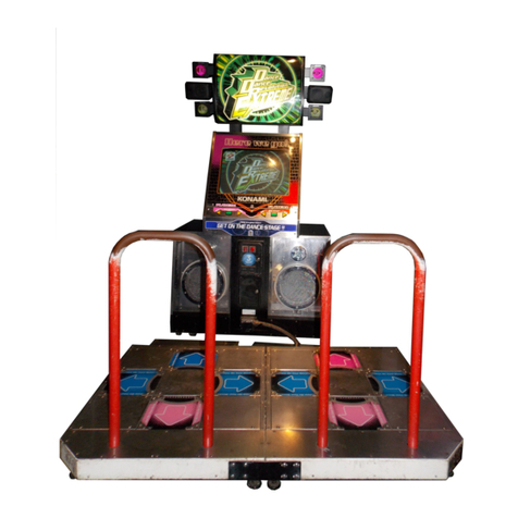
Konami
Konami DanceDanceRevolution Operator's manual
