Exit Light ESC-200P User manual
MANUAL
Addressable Combination System
ESC-200P

Hermiankatu 6–8, 33720 Tampere | +358 10 773 5400 | info@exilight.com |
MANUAL
Quick Start
1. Install the panel using mounting holes.
2. After luminaires are installed (please note that the luminaires are suited for ESC-200P
system), connect cables of loops to central panels.
•Panel has 10, 16 and 24 sections for addressable luminaires. These are divided into
two loops (L1 and L2), half-by-half: 5 + 5, 8 + 8 and 12 + 12.
•In section could be mixed with emergency lights and exit lights.
•Maximum 20 luminaires can be attached on one section, in total 200 luminaires per one
panel.
•Do not connect luminaires with live voltage on panels!
•Make sure that +, - and G markings are connected right way around.
3. Panel has three (3) outputs for 230V emergency lights. Do not under any circumstance
connect addressable LED emergency lights to these outputs. Outputs are only applicable to
be used for 230V emergency lights.
4. Connect the small NiMH battery to panel printed circuit board and 12 V backup batteries to
panels battery cables. Backup batteries of panels have a voltage of 12 V.
5. Connect power to central panel power supply.
6. From control panel, choose ”INVERTER USE” and choose either ”ON + BATT. CHECK” to
operate as central battery system and to have monitoring for both batteries and inverter.
”ON + BATT.CHECK” is default mode of ESC-200P panel.
7. Press the MENU-button and go to ”START NEW INSTALLATION”. You can scroll the menu
with UP and DOWN buttons. New commissioning is started by pressin MENU-button. On
display there is a note “INSTALLATION IN PROGRES” and ”TIME ABOUT 30 MIN”. Panel
writes to its memory found luminaires from each line. Luminaire inventory can be scrolled
with LEFT and RIGHT buttons. After commissioning has been executed panel returns to a
normal state.
Control panel has two lines for luminaires. Maximum capacity of lines are 100
luminaires per loop, 200 luminaires per one panel.
8. When panel has found all luminaires in loops, “EVERYTHING OK” is appeared on display.
Hermiankatu 6–8, 33720 Tampere | +358 10 773 5400 | info@exilight.com |
MANUAL
9. SETTING THE TIME AND DATE
Set the time and date in ”SET” ”SET DAY+TIME” (choose with LEFT-button). Choose
time with SET-button. Time format is dd.mm.yyyy hh:mm. as an example ”08.03.2007
12:10”. Parameters can be scrolled with UP and DOWN buttons. Parameter is entered with
SET button and panel will be moved to next parameter. New time will be set if all
parameters are configured. If one leaves the view with RIGHT button before all parameters
are set, new time is not entered into system.
10. LUMINAIRES
Address information is pre-provisioned into luminaire. Two address stickers are provided
with luminaire. One is to be attached in to luminaire and one to electrical design
documentation.
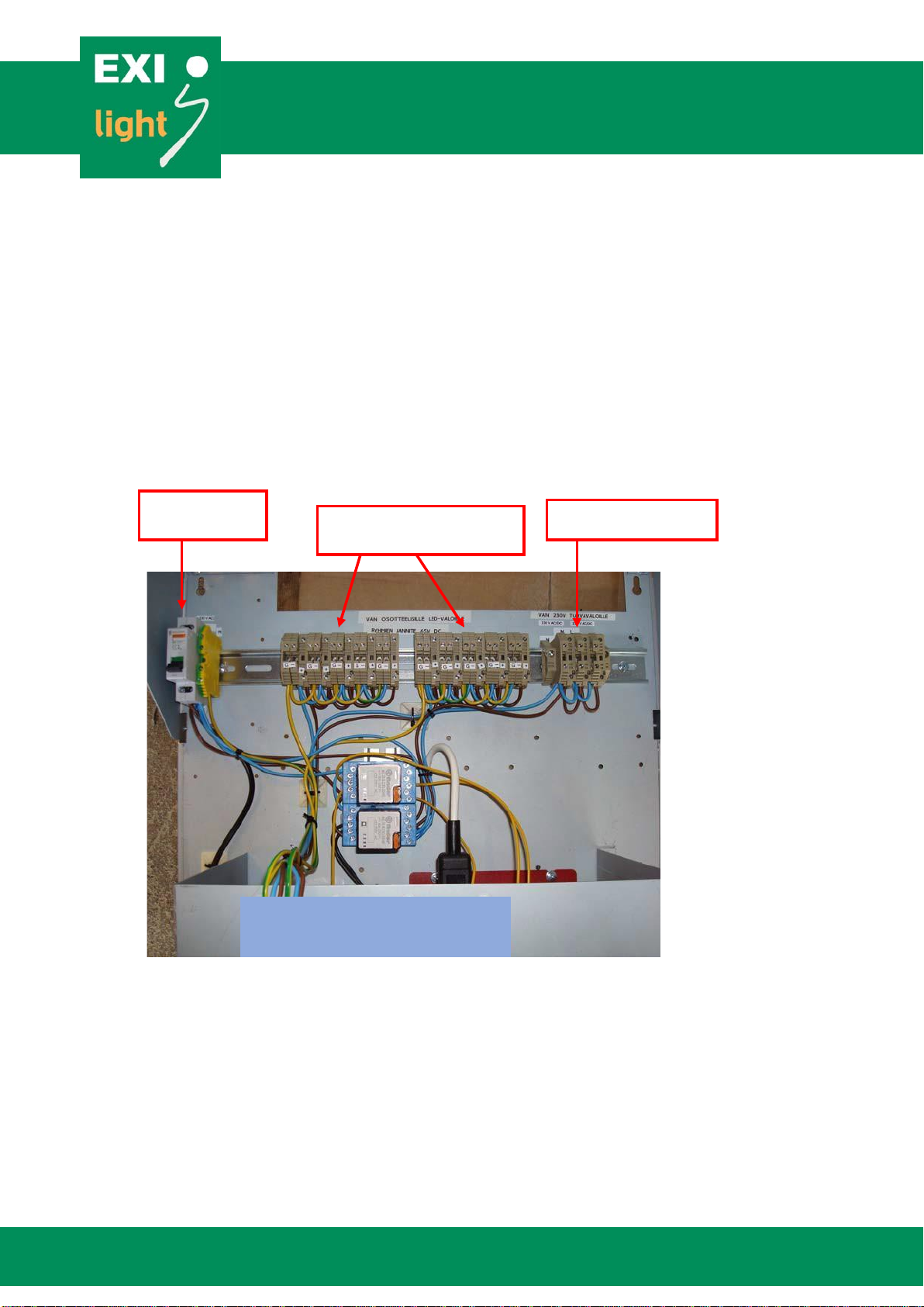
230 V AC
panel feed
Addressable outputs
Un = 65
V DC
230 V AC emergency
light output
ESC-200P PANEL
Hermiankatu 6–8, 33720 Tampere | +358 10 773 5400 | info@exilight.com |
MANUAL
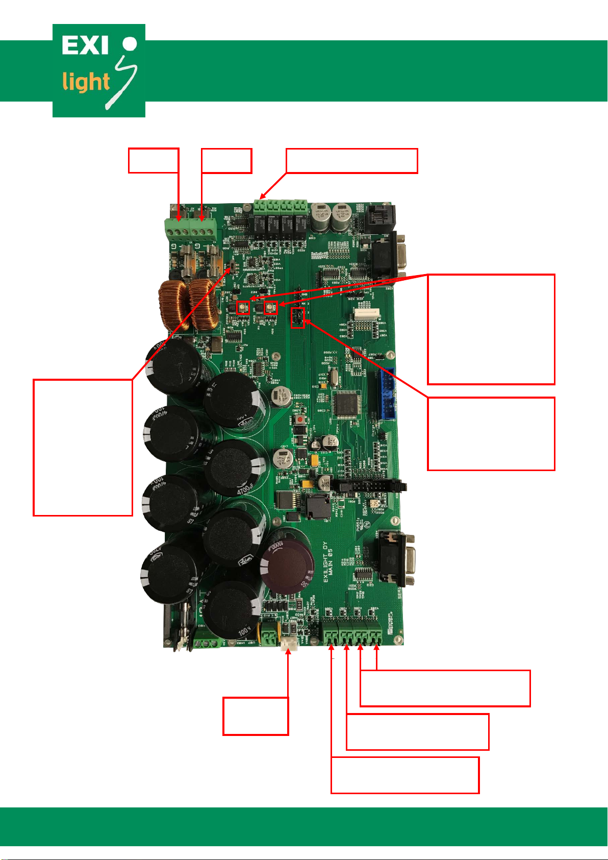
Loop 1
Loop 2
Dry contact output
Internal wiring
External control loop 2 dry
contact
External control loop 1 dry
contact
Battery
connector
Swith K3: Filter
ON/OFF (default
ON). If panel is to
be connected to
earlier generation
of ESC-200P set
filter OFF.
Jumpers X317 and
X318: Do not change.
By default they are
connected and enable
communication on line.
Trimmers R33 and R34:
Line output power. By
default same as
luminaire powers. Do
not change without
contacting supplier.

Hermiankatu 6–8, 33720 Tampere | +358 10 773 5400 | info@exilight.com |
MANUAL
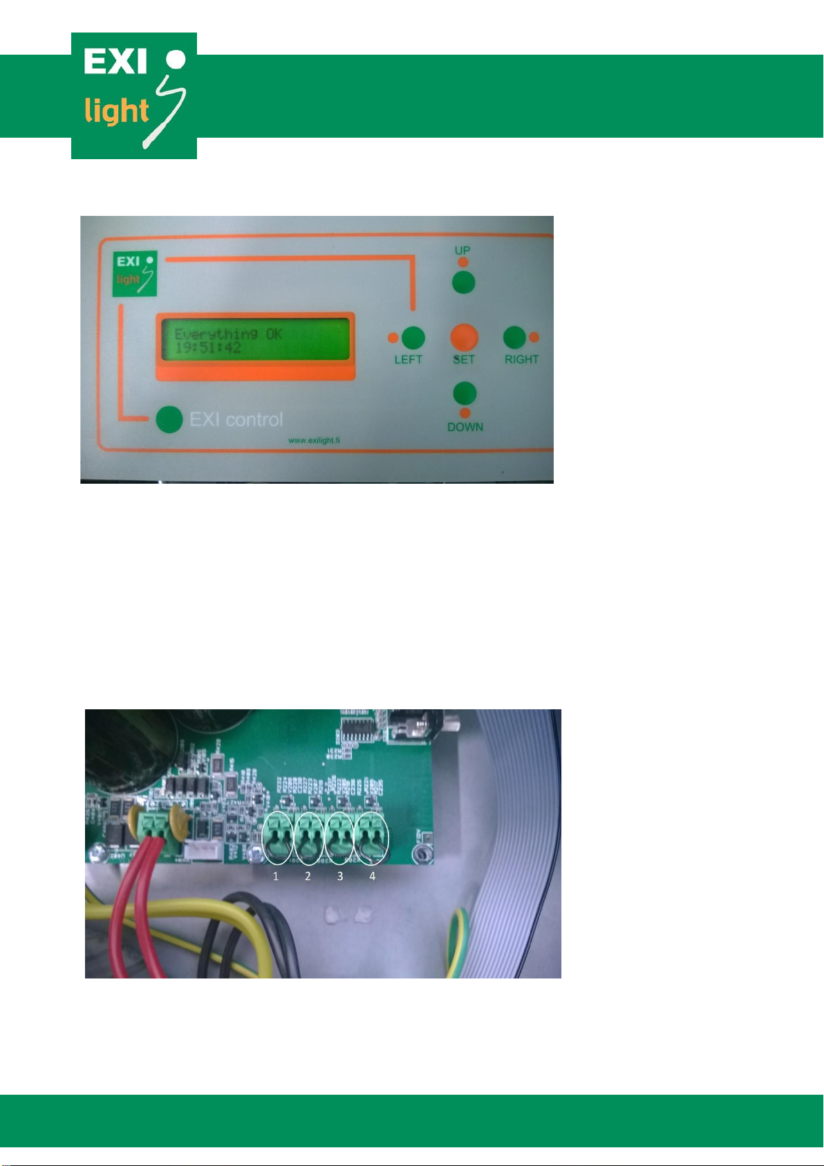
Operating the ESC-200P Panel
There is a 2 line LCD display (20 char. / line) and five operating buttons: “LEFT”, “RIGHT”, “UP”,
“DOWN” and “SET”.
Under the “SET” button there is a menu of rarely needed but never the less important
functions. These functions may come handy while operating the center.
The MENU includes:
1.
Normal status
a.
Everything Ok
b.
An Error code when something is wrong
2.
Browse error
3.
Annual test time
4.
LED test time
5.
Monthly test time
6.
Demo mode
7.
Start monthly test
8.
Start annual test
9.
Annual test duration
10.
Area monitoring
11.
Current measuring
12.
GND leakage set up
13.
Change language
a.
English
b.
Svenska = Swedish
c.
Suomi = Finnish
14.
Read address form PC
15.
Stop / Allow communication errors
16.
Browse appliances
17.
Inverter use
18.
Print appliance ID
19.
Event log
20.
Remove appliance
21.
Print errors
22.
Start new installation
23.
Set day + time
24.
Emergency lights on

Hermiankatu 6–8, 33720 Tampere | +358 10 773 5400 | info@exilight.com |
MANUAL
1. Normal status
Everything Ok: The display shows date and time
- “Everything Ok” “HH:MM”
Error code
- The display shows the latest error that has not been set off
- The top line in the display shows the amount of errors and the lower line shows the
appliance ID (D), the loop (L) and the error code (E). For example: Not set off 005/005 //
D06397 L2 E03
- You can what the error code means by pushing the “LEFT” button. It will indicate what the
error code actually means, For example “led disconnected”
- To set off the error codes you have to push the “RIGHT” button two times.
2. Browsing errors
By pushing “SET” you can browse the errors that have been detected in the past.
The errors will be shown chronologically so that the latest error will be the first to show up on the
display. You can browse the errors by pushing “UP” or “DOWN”.
The display shows when the error was detected, appliance ID (D), loop (L) and the error code (E).
All error codes can be found in table 1 and 2.
3. Annual test time
Set the time and date for annual duration test
4. LED test time
Set the time for LED blink test.
5. Monthly test time
Set the time and date for monthly test.
6. Demomode
Here you can set demomode on. Demomode is only for presentation.
When the demomode is on the errors come more quickly to the panel.
7. Start monthly test
Function test is done automatically every month but here you can start that test manually.
8. Start annual test
Annual duration test is done automatically every year but here you can start that test manually.

Hermiankatu 6–8, 33720 Tampere | +358 10 773 5400 | info@exilight.com |
MANUAL
9. Annual test duration
Choose annual test duration, 1h or 3h.
10. Area monitoring
Control area monitors connected to the system.
11. Current measuring
12. GND Leakage Set Up
Not valid in ESC-200P system.
13. Change language
Here you can set the operating language to be English, Swedish or Finnish.
14. Read address from PC
Appliance IDs can also be read form the PC.
15. Stop / Allow communication errors
Normally these communication errors are stopped.
The center checks if there is some communication errors with appliance IDs
16. Browse appliances
Here you can check all the appliances connected to the center.
First you have to choose Loop 1 or Loop 2 by pushing “SET” and then you can browse appliances
by pushing “UP” or “DOWN”.
17. Inverter use
This is supposed to be switched ON when using ESC-200P system with central battery.
18. Print appliance ID
19. Event Log
You can connect your PC with the ESC-200P and print out the events via Ethernet converter.
20. Remove appliance
When removing appliance from Loop 1 or Loop 2 you also have to remove that appliance from the
appliance list.

Hermiankatu 6–8, 33720 Tampere | +358 10 773 5400 | info@exilight.com |
MANUAL
- This is because the center is constantly checking the status of every appliance and if the
appliance has been removed it can’t communicate with the ESC-200 center.
You can remove appliance from the appliance list as follows:
- From the menu choose “Remove appliance”
- Then choose if the appliance is in Loop 1 or Loop 2
- Find the appliance that needs to be removed by browsing the list with “UP and “DOWN”
buttons
- When you find the right appliance ID that has to be removed push “SET” three times. This
is to make sure that you don’t accidentally remove appliance that you are not supposed to
remove.
21. Print errors
You can connect your PC with the ESC-200 and print out the errors.
22. Start new installation
By choosing “Start new installation” the center finds all the appliances connected to the system.
Center ask before new installation”delete memory” you can choose ”no” or ”yes”. If you choose
”yes” centter will delete luminaire addresses what is in memory.
23. Set day + time
Here you can set the date and time for the system
24. Emergency lights on
This is to start test for the system. This is used to check the communication between panel and
luminaires. Communication should be Ok if emergency luminaires are set ON with this test
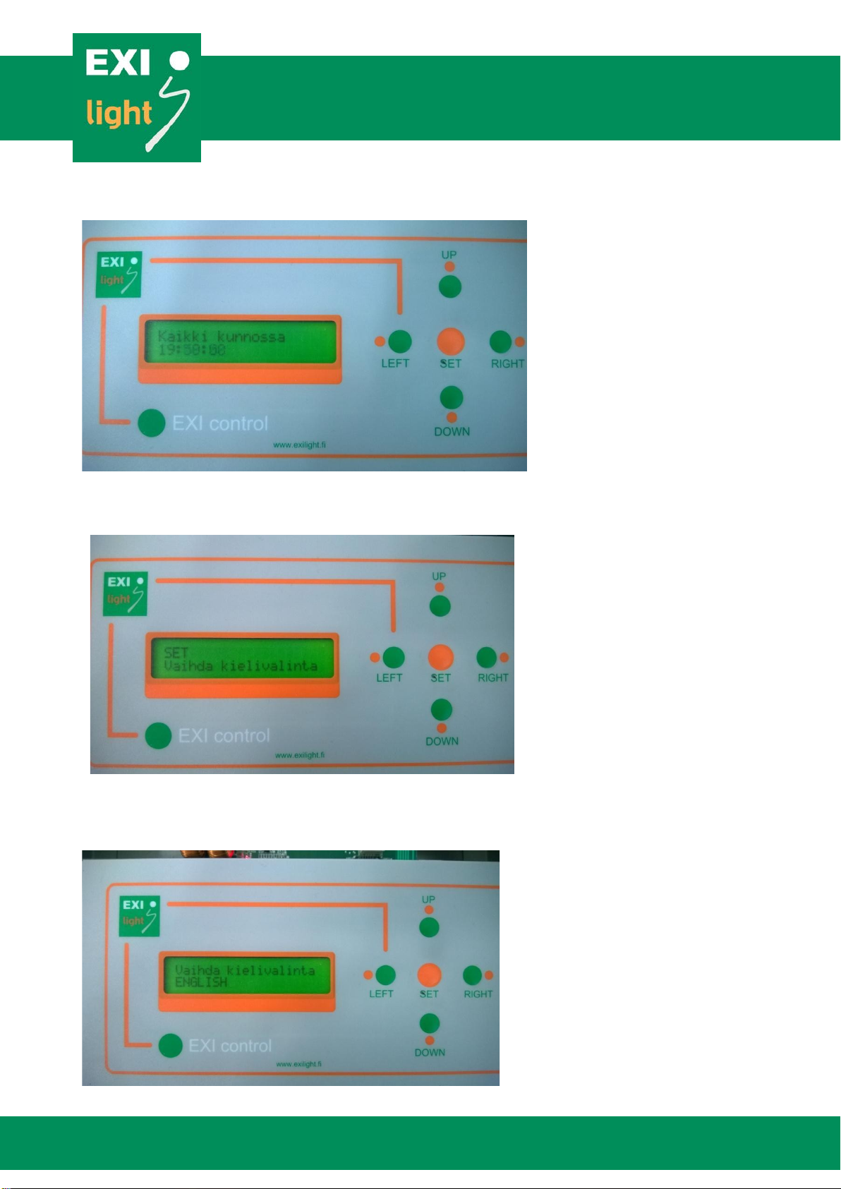
Changing the Operating Language
If the ESC-200P emergency lighting center is delivered to you with settingsin
Finnish, here is how you can change the language toEnglish.
You start by pushing the “SET”button when you have the operating status shownin the
picture 1.
Then push the “DOWN”button three (3) times to get the display of picture2.
After that push “SET”and by “UP”or “DOWN”button choose “ENGLISH”asshown in
the picture 3. Push “SET”to select thelanguage.
Now you have the ESC-200P Emergency Lighting Center set inEnglish.
Hermiankatu 6–8, 33720 Tampere | +358 10 773 5400 | info@exilight.com |
MANUAL
Picture 1.
Picture 2.

Hermiankatu 6–8, 33720 Tampere | +358 10 773 5400 | info@exilight.com |
MANUAL
Picture 3.
Checking Error Status
If the display is showing an Error Code (Picture 4 and 5), you can set it off (Picture 6 and
7) to make sure it is actually a real Error. If the Error is real it will come back to the display
within few minutes.
You can set off the Error Code by pushing the ”RIGHT”button two (2) times inthe
display shown in pictures 4 and 5 (demonstrated in pictures 6 and7).
If the Error Code returns to the display and it’s a real Errorthen:
-
Find out what the Error Code stands for (Picture 5).
-
Find out where in the building that Emergency or Exit light is located and go
check the lights status.
Picture 4. Reading the Error Code from the ESC-200 display.

Hermiankatu 6–8, 33720 Tampere | +358 10 773 5400 | info@exilight.com |
MANUAL
Picture 5. You can see what the Error Code actually means by pushing ”LEFT”
button.
Picture 6. Set off the Error Code by pushing ”RIGHT”.
Hermiankatu 6–8, 33720 Tampere | +358 10 773 5400 | info@exilight.com |
MANUAL
Picture 7. When the Error is set off the display will show “Everything OK”.
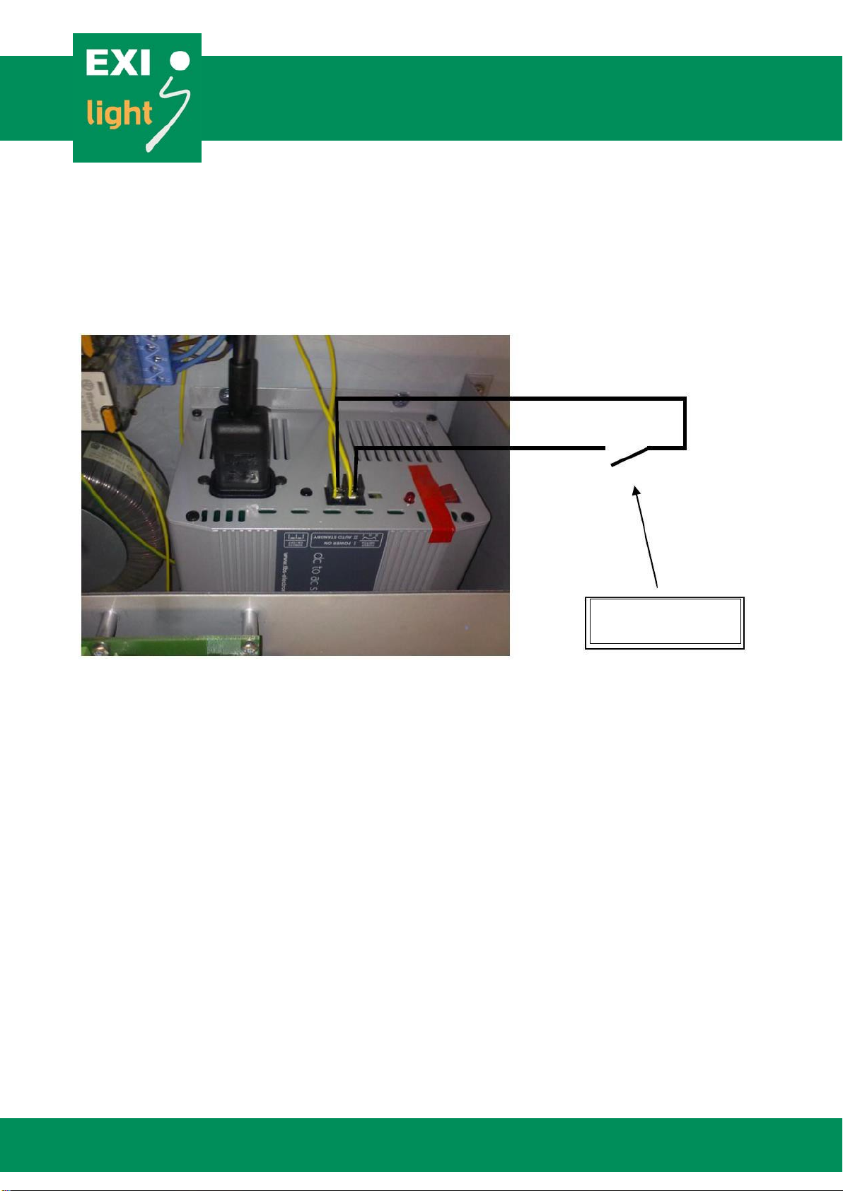
Remote controlling the Emergency lights
In case that there are some Emergency lights lit along with the Exitlights:
Make sure that the Remote Control is not on (Picture 8.).
-
Remote controlling the Emergency lights is operated with NCcontact. If there is no
remote controlling the lights, there is a loop in the terminals as shown in Picture 8.
-
If there is a blackout or the remote control is on, the buttons in Centers display
stops working. This is for as long as the blackout or remote control is on.
Picture 8. Remote controlling the ESC-200 Center. Input 1 controls Emergency lights
in Loop 1, input 2 controls Emergency lights in Loop 2, inputs 3 and 4 controls all the
emergency lights connected to the ESC-200 Center.

Hermiankatu 6–8, 33720 Tampere | +358 10 773 5400 | info@exilight.com |
MANUAL
Setting the luminaire location
Connect the panel to your PC.
Open EXIL2 software and choose the right port and language.
Press the read button. After the software has read all the addresses you can write or
change the locations. Maximum letter is 16 in one location.
Write button write the locations to the panel.
With import button you can bring file which include the addresses. The file must be written
in the following way: every lane has Loop information, address information, location
information and it must be separate with comma. The file must be text file. For example:
Loop1,17515,Hall 1
Loop1,17670,Hall 2
Loop1,17701,Corridor
Loop1,17793,Garage
Loop2,17753,Garage2
Loop2,17792,Hall 3
With export button you transfer the tex file to the panel.
After the panel has read the file, locations should be now in your panel. You can now
remove the port cable.

Hermiankatu 6–8, 33720 Tampere | +358 10 773 5400 | info@exilight.com |
MANUAL
Picture 9. Luminaire location setting PC software.

Hermiankatu 6–8, 33720 Tampere | +358 10 773 5400 | info@exilight.com |
MANUAL
Working Principles of ESC-200P
Data transfer protocol is called DC Power Line Communication
-
The information runs in the same cable with the voltage
The Center is constantly checking the lights operatingstatus
-
The first error doesn’t show up on the display. The Error Code shows uponly if
the same light/address gives the error ten (10)times.
oThis is how we can reduce failures coming from othernetworks.
oThere are no external signs about the Center checking theoperating
status.
-
How long does it take to Error Code to show up on Centers display depends on
how many lights you have in the system and how they areinstalled.
-
Checking the LEDs makes the Emergency light blink briefly about once a
day.
The ESC-200P Center makes the battery test every month.
-
The Center makes the luminaires to work with batteries during the test. The
voltage (65VDC) still remains in the line.
-
The test lasts for 30 minutes and the Emergency lights light up duringthe
test.
-
The automatic testing cannot be turnedoff.
Hermiankatu 6–8, 33720 Tampere | +358 10 773 5400 | info@exilight.com |
MANUAL
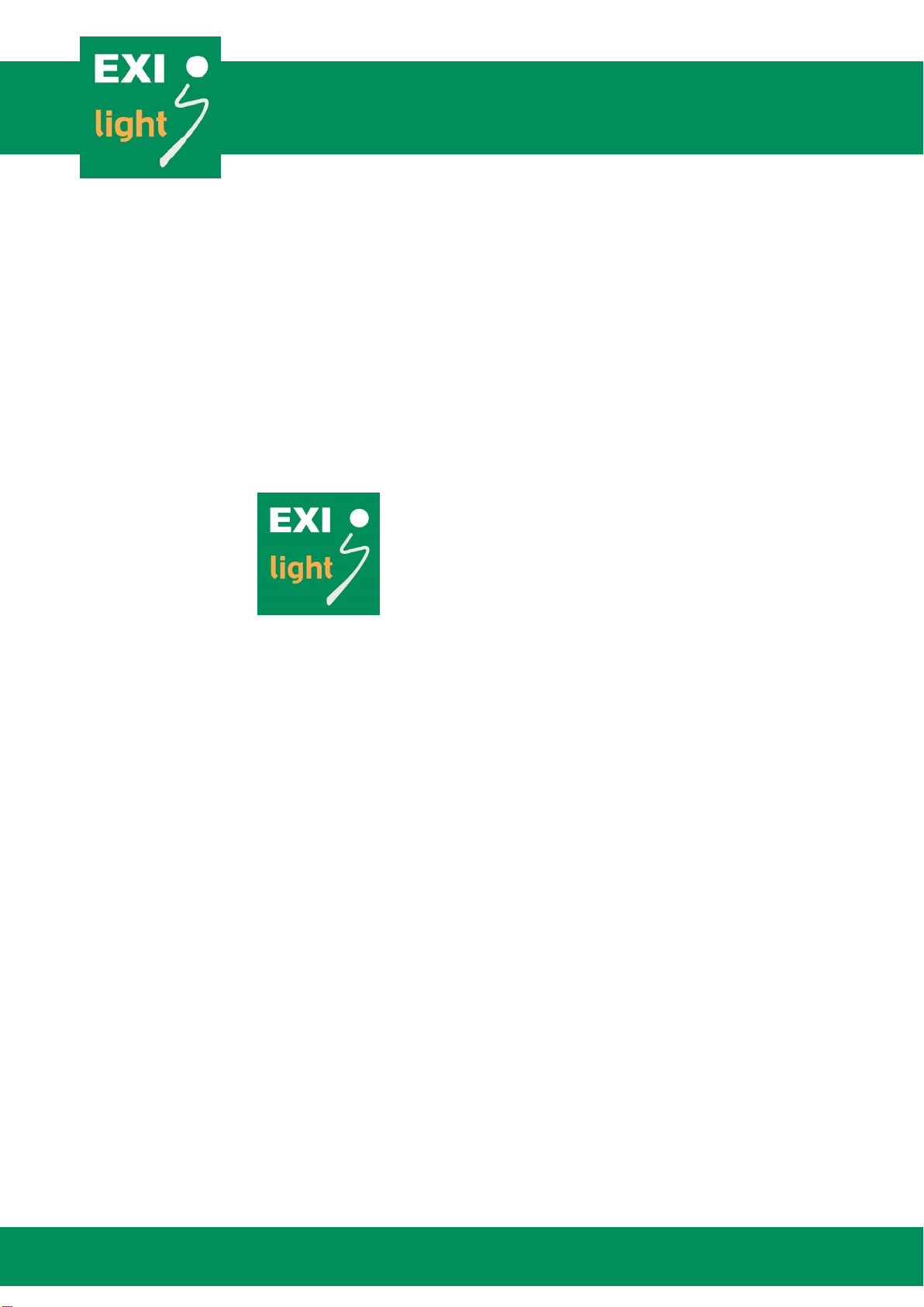
Controlling 230V emergency lights with external
control
Three (3) 230V emergency light outputs can be turned on with dry contact by connecting inverter to
external control according to picture 9.
Picture 9: 230V emergency light outputs control
ESC-200P design and cabling principles
In order for the proper functioning of system, please use following design and cabling principles:
•Always use shielded FRHF-cable.
•Keep lines as short as possible (maximum distance around 300 m).
•Maximum number of 100 luminaires per line.
•Place the luminaires to lines with as even spacing as possible.
•If long spans are needed, prepare own line for it and do not include any other luminaires on
the way.
•Cable crimping should be kept to a minimum on luminaires and switch boxes.
•In luminaire connections take care that positive and negative connections are connected
right way around. Also take care to connect earth conductor.
•2 Area Monitoring Units(AMUSs) is comparable to one luminare. So if you have 80
luminaires on line, maximum AMUs is 40 per line. (max100 luminare per line)
•If Area Monitoring Units (AMUs) are being used, ensure that between AMUs and controlled
luminaires there are more than 5 meters of cable to ensure proper communication.
For example AMU
can be used.

Hermiankatu 6–8, 33720 Tampere | +358 10 773 5400 | info@exilight.com |
MANUAL
Example cabling
•TVK is same as Control Panel ESC-200P
•Cabling FRHF
•AV is same as AMU
Hermiankatu 6–8, 33720 Tampere | +358 10 773 5400 | info@exilight.com |
MANUAL
Service and Maintenance
Service and maintenance of system has to be conducted by person with professional and
knowledgeable person. Constant maintenance is needed in order to ensure the proper function of
the system.
Warranty
Warranty terms under the supplier’s standard terms. In case of system faults always consult your
sales representative:
EXILIGHT OY
Hermiankatu 6–8 A
FI-33720 Tampere
Finland
+358 10 773 5400
info@exilight.com
Hermiankatu 6–8, 33720 Tampere | +358 10 773 5400 | info@exilight.com |
MANUAL
ESC system error codes
Table 1: Luminaires’ errors
ERROR REMARK ERROR
CODE
Battery disconnected
Not to be noted in central battery use.
E01
Short circuit in battery
Not to be noted in central battery use.
E02
Led disconnected
E03
Short circuit in LED
E04
Battery condition fail
Not to be noted in central battery use.
E05
Battery failed during test.
Not to be noted in central battery use.
E08
Battery disconnected
Not to be noted in central battery use.
E01
Table 2: Central panel errors
ERROR REMARK ERROR
CODE
Communication error
Error in the communication between
luminaire and panel.
E14
Blackout
Not an actual error. Doesn’t need to be set
off. Is noted in the error log.
E15
Low control voltage
Control voltage drops, but doesn’t cause a
blackout.
E16
Loop 1 dead
Control voltage too low or fuse is broken.
E17
Loop 2 dead
See above.
E18
Earth leakage in loop 1
E19
Earth leakage in loop 2
E20
Excess current in loop 1
Overload in loop 1
E21
Excess current in loop 2
Overload in loop 2
E22
Inverter or battery fail
Inverter fail during test
E23
Inverter or battery fail
Battery fail during test
E24

Hermiankatu 6–8, 33720 Tampere | +358 10 773 5400 | info@exilight.com |
MANUAL
This page is intentionally left blank.
Table of contents
Popular Safety Equipment manuals by other brands

KRATOS SAFETY
KRATOS SAFETY FA 10 401 00 manual

Petzl
Petzl DUAL CANYON GUIDE TECHNICAL NOTICE

Roger Technology
Roger Technology R85 Series Instruction and warnings for the installer

RIB
RIB F97I Guide

South-Tek Systems
South-Tek Systems N2-BLAST FPS-500 O & M Manual

SKYLOTEC
SKYLOTEC ANCHOR ROPES Instructions for use


