Würth BFD User manual

Verbindungsmittel
lanyards
Gebrauchsanleitung
Instructions for Use
Istruzioni per l’uso
Instructions d’utilisation
Instrucciones de uso
Instruções de serviço
Gebruiksaanwijzing
Brugsanvisning
Bruksanvisning
Käyttöohjeet
Bruksanvisning
Οδηγίες χειρισμού
Talimatlar
Instrukcje
Utasítás
Instrukce
Inštrukcie
Instrucţiuni
Navodila
инструкции
Juhised
Instrukcijos
Instrukcijas
инструкции
инструкције
Instrukcije
2
+
89/686/EEC
0123
1
GBA_Verbindungsmittel-MAT-BA-WU-0144.indd 1 02.07.16 13:47

.................................. 9… 11
.................................. 12… 14
.................................. 15… 18
.................................. 19… 22
.................................. 23… 26
.................................. 27… 30
.................................. 31… 34
.................................. 35… 38
.................................. 39… 41
.................................. 42… 45
.................................. 46… 49
.................................. 50… 53
.................................. 54… 56
.................................. 57… 60
.................................. 61… 64
.................................. 65… 67
.................................. 68… 70
.................................. 71… 73
.................................. 74… 76
.................................. 77… 80
.................................. 81… 83
.................................. 84… 86
.................................. 87… 89
.................................. 90… 93
.................................. 94… 96
.................................. 97… 99
2
1+
Informationen (Beide Anleitungen beachten)/
Informations (Use both manuals)
GBA_Verbindungsmittel-MAT-BA-WU-0144.indd 2 02.07.16 13:47

3
Nutzung in Ordnung/Usage okay
Vorsicht bei der Nutzung /
Proceed with caution during usage
Lebensgefahr/Danger to life
Zusätzliche Absturzsicherung erforderlich/
Additional Fall Arrest security required
Informationen (Beide Anleitungen beachten)/
Informations (Use both manuals)
1.) Normen/Standards
Europa
EN 795
DIBt
+EN 354(4)
+EN 355 (3)
+EN 362
(1/2)
BFD EN 355
GBA_Verbindungsmittel-MAT-BA-WU-0144.indd 3 02.07.16 13:47

4
∆
+ ca. 1,0 m
Safety distance
Abb. 3
Anchor
point
Abb. 2
Fall arrest (e.g. EN 361)
„A“ „A“
I-Version Y-Version
3
1
4
Abb. 3
2
2.) General Informations/Types
Abb. 1
2.1 2.2
GBA_Verbindungsmittel-MAT-BA-WU-0144.indd 4 02.07.16 13:47

5
∆
+ ca. 1,0 m
Safety distance
Abb. 3
Anchor
point
Abb. 3
EN
355
(354)
Max.
Freifallhöhe
max. freefall distance
4 m
Max. Fangstoß
max. fall impact
(F)
6 kN
Max. Bremsstrecke
max. braking
distance (Δ )
1.75
m
Max. Länge
max. length
() 3.2
2,0 m
Name FASTENER BFD
Products
EN360
SKYLOTEC
Fallarrestblock
EN361
Harness
EN355
Shockabsorber
L-0005-F-HSG
2,0m
+x
+1,55m
Thissideup!
r0,5mm
min
r>0,5mm
min
3.6 b
3.6 a3.6 a
Abb. 4
GBA_Verbindungsmittel-MAT-BA-WU-0144.indd 5 02.07.16 13:47

6
Abb. 4
Name FASTENER BFD
Products
EN360
SKYLOTEC
Fallarrestblock
EN361
Harness
EN355
Shockabsorber
L-0005-F-HSG
2,0m
+x
+1,55m
Thissideup!
r0,5mm
min
r>0,5mm
min
I-Version
V-Version –
Y-Version
RfU 11.060.074
r>0,5 mm
R<0,5mm
Wrap around
–
RESCUE LOOP –
GBA_Verbindungsmittel-MAT-BA-WU-0144.indd 6 02.07.16 13:47

7
3. Verbindungsmittel/Lanyards
L+/-
2,5 m
3.1 a
L+/-
3.1 b
L max.
3.2
3.3 3.4
3.5
min.
0,8 m
3.6 a Abb. 4 3.6 b
GBA_Verbindungsmittel-MAT-BA-WU-0144.indd 7 02.07.16 13:48

8
4. Verwendung als Anschlagschlinge/Use as anchor
loop
7. Fallindikator/Fall indicator
F max.
4.1 4.2
max. 90°
4.3
4.4 4.5 4.6
6. Rettung/Rescue
A
A
GBA_Verbindungsmittel-MAT-BA-WU-0144.indd 8 02.07.16 13:48

9
Gebrauchsanleitung
Nutzung in Ordnung
Vorsicht bei der Nutzung
Lebensgefahr
So nicht anwendbar
1.) Normen
2.) Allgemeine Informationen/Typen
Das dämpfende Verbindungsmittel (VBM) dient in der Verbindung mit
einem Auanggurt ausschließlich zur Absicherung von Personen, die
während ihrer Arbeit der Gefahr eines Absturzes ausgesetzt sind (z.B.
auf Leitern, Dächern, Gerüsten, usw.). Lesen und verstehen Sie alle
dem Produkt beiliegenden Anleitungen vor der Verwendung. Die
Lebensdauer ist abhängig von der Nutzungshäugkeit und den
Umgebungsbedingungen. Ein Verbindungsmittel (z.B. nach EN 354)
darf nur zur Sicherung eingesetzt werden, wenn zusätzlich ein
Dämpfer nach EN 355 verwendet wird.
Funktion: Der integrierte Dämpfer begrenzt die bei einem Absturz
entstehende Energie auf ein körperverträgliches Maß durch
Längenänderung (vgl. Δl, Abb. 2+3). Das VBM ist nach einer
Sturzbelastung nicht mehr verwendbar! Falldämpfer anlegen (vgl.
Abb. 1) 1. Verbindungselement (1) ausschließlich an einer mit „A“
gekennzeichneten Auangöse am Auanggurt (z.B. nach EN 361)
einhaken. 2. gegenüberliegendes Verbindungselement (2) an einem
geeigneten Anschlagpunkt (z.B. nach EN 795, ANSI) befestigen.
Das VBM (3) darf nicht behindert werden und sollte keinesfalls über
Kanten oder Umlenkungen geführt werden, wenn es dafür nicht
ausdrücklich freigegeben ist. In Abb. 5 ist erkennbar, welche VBM
kantengeeignet (R>0,5mm) sind und welche nicht. Diese
Kanteneignung wurde in einem Fallversuch über eine gratfreie Kante
mit einem Radius >0,5mm ermittelt. Auf Grundlage dieses Tests sind
die gekennzeichneten VBM bei einem Sturz über eine Kante
anwendbar. Ungeachtet dieser Prüfung muss immer, wenn die Gefahr
besteht über eine Kante zu stürzen,folgendes berücksichtigt werden:
1. Wenn die durchgeführte Risikobewertung vor Beginn der Arbeit
zeigt, dass die Kante besonders „scharf“ (R<0,5mm) und/oder „nicht
frei von Graten“ ist, muss ein Sturz über die Kante durch technische,
oder organisatorische Maßnahmen verhindert werden, oder wenn
möglich ein Kantenschutz montiert werden.
Die Umlenkung an der Kante muss mindestens 90° sein.
GBA_Verbindungsmittel-MAT-BA-WU-0144.indd 9 02.07.16 13:48

10
Das VBM darf nicht verlängert, geknotet oder im Schnürgang
verwendet werden (Abb. 3 + 3.2-3.4)
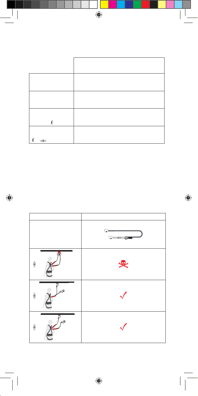
2.1) Verwendung der Vorderen Auangöse
2.2) Verwendung der Hinteren Auangöse
3.) Verbindungsmittel
3.1) (a+b) Die Einstellung der Länge und das Anlegen sollte nicht im
absturzgefährdeten Bereich erfolgen.
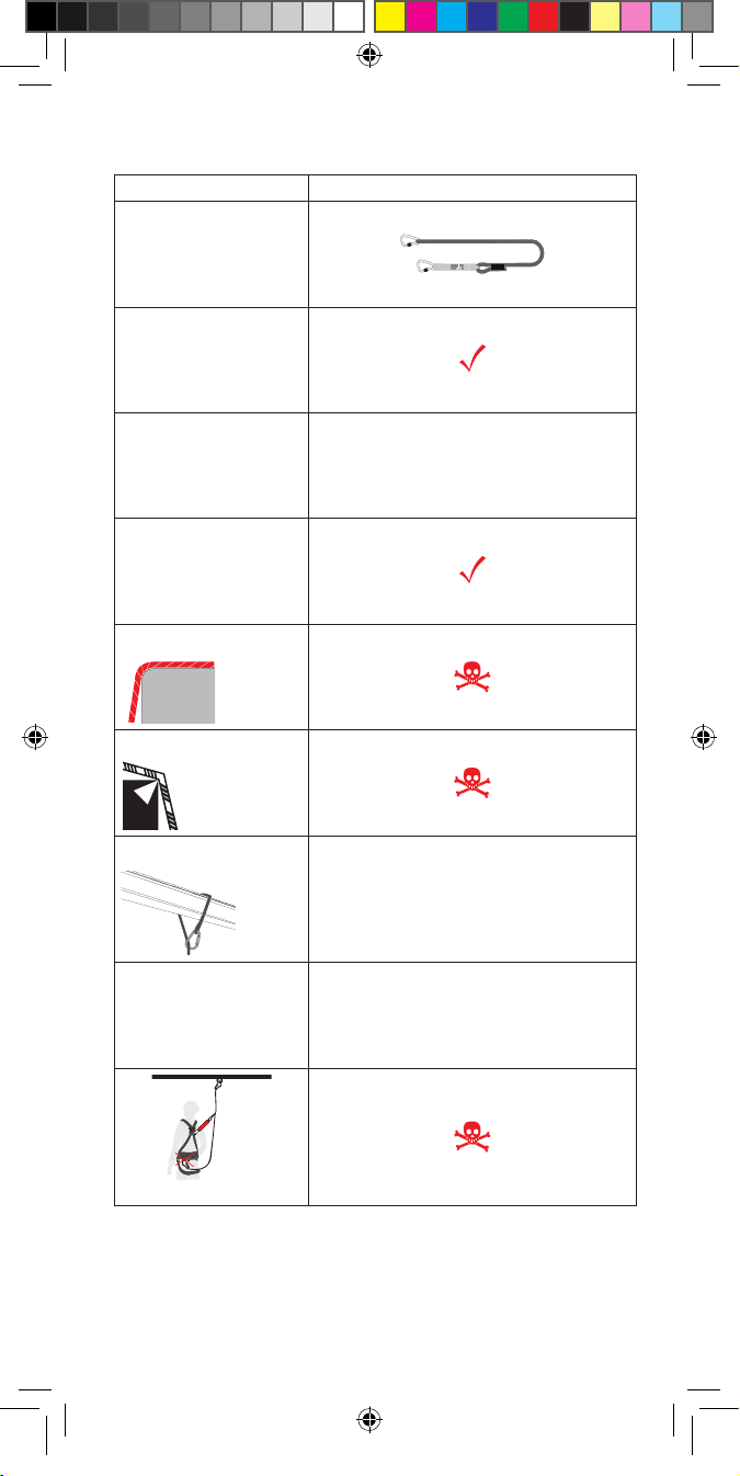
3.2) Die Gesamtlänge des VBM, (einschließlich Dämpfer und
Verbindungselementen) darf die Werte von Abb. 3 nicht überschreiten.
3.3) Das VBM nicht knoten.
3.4) Das VBM nicht im Schnürgang verwenden
3.5) Sicherheitskarabiner und/oder Verbindungselemente vor Quer-
und Knickbelastung schützen.
3.6) (a+b) Die jeweilige Anschlagart ist anhängig vom jeweiligen Typ
des VBM und richtet sich nach den Angaben der Tabelle Abb. 4
4.) Verwendung als Anschlagschlinge
4.1) Die im Falle eines Sturzes auftretenden maximalen Kräfte im
Bauwerk sind abhängig vom verwendeten Falldämpfer. Die in das
Bauwerk eingeleitete Kraft entspricht der max. Kraft auf die der
Falldämpfer die Sturzbelastung reduziert (Abb. 3). Bei zugelassener
Verwendung durch mehrere Personen sind die max. Auangkräfte zu
addieren.
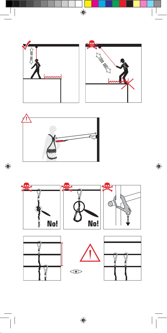
4.2) Schlaseil vermeiden.
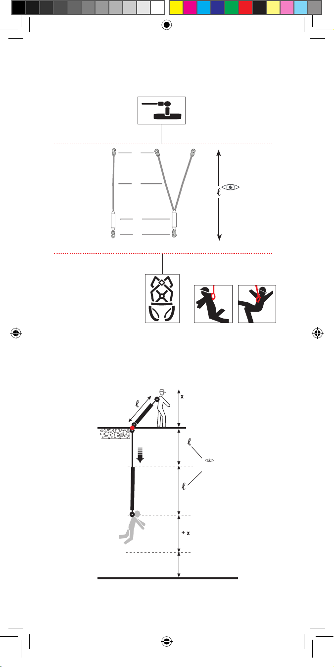
4.3) Der Anschlagpunkt sollte sich möglichst senkrecht über der
Arbeitsstelle benden. Bendet sich der Anschlagpunkt unterhalb, so
besteht im Falle eines Sturzes die Gefahr des Aufschlagens auf tiefer
gelegene Bauteile. Bendet sich der Anschlagpunkt seitlich, so
besteht die Gefahr des Aufschlagens an seitliche Bauteile. Um einen
Pendelsturz zu verhindern sollte der Benutzer die seitlichen
Bewegungen zur Mittelachse auf ein Maximum von ca. 45°
begrenzen. Sollte dies nicht möglich sein, oder größere Auslenkungen
erforderlich sein, sollten keine einzelnen Anschlagpunkte verwendet
werden, sondern ein System nach z.b. EN 795 Klasse D (Schiene)
oder C (Seil). Die Höhe des Anschlagpunktes und der benötigte
Bodenfreiraum muss in jedem Fall ausreichend bemessen werden um
die Wirksamkeit des Systems zu gewährleisten (vgl. Abb. 2):
Bremsstrecke des Falldämpfers (vgl. Δl, Abb. 2)
+ Ausgangslänge des Verbindungsmittel (vgl. l, Abb. 3)
+ Körperlänge (vgl. x, Abb. 2)
+ Sicherheitsabstand (ca. 1m, vgl. Abb. 2)
+ ggf. Dehnung der Anschlageinrichtung (z. B. EN 795 B/C, vgl.
Gebrauchsanleitung des Herstellers)
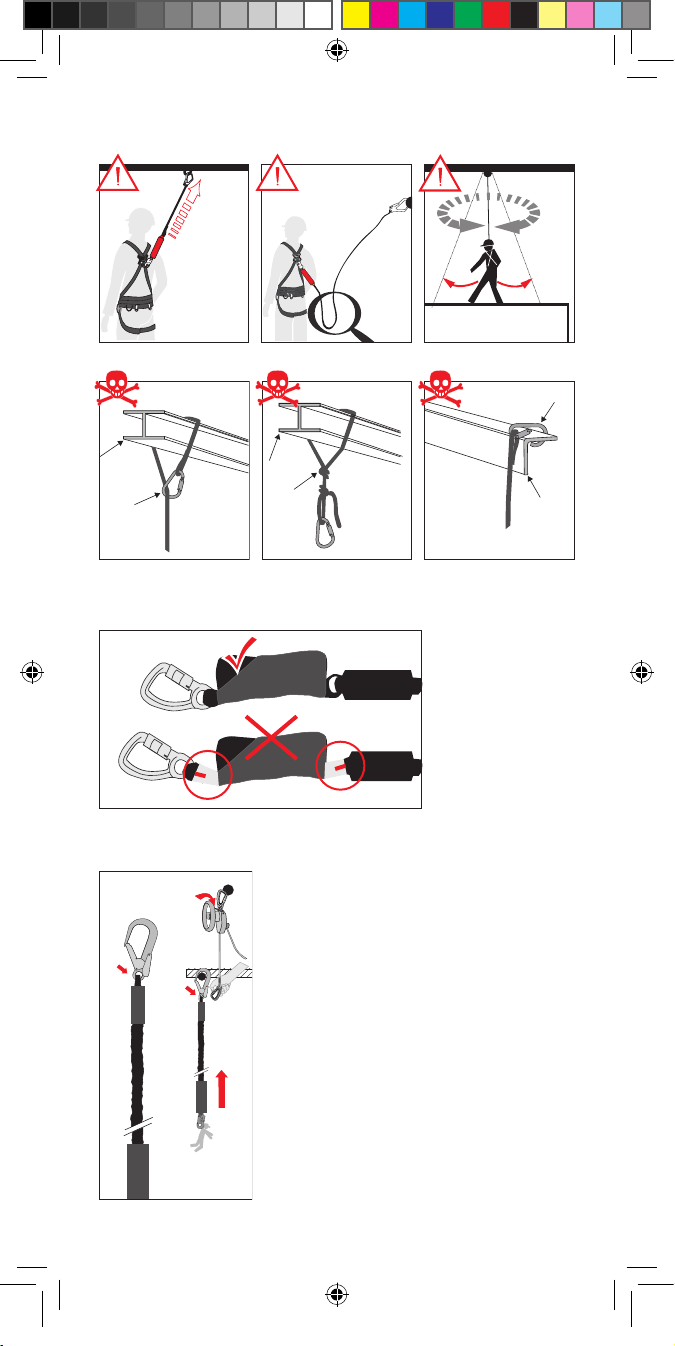
Den Falldämpfer nicht als Halteseil verwenden, d. h. sich nicht an ihm
festhalten und hochziehen. 4.4 - 4.6) Auf lose Trägerenden achten/
nicht im Schnürgang verwenden/Verbindungsmittel nicht knoten/
GBA_Verbindungsmittel-MAT-BA-WU-0144.indd 10 02.07.16 13:48

11
Karabiner immer richtig verschließen.
7.) Fallindikator
Wenn an den Produkten Fallindikatoren verbaut und diese zu
sehen sind (auch, wenn kein Absturz erfolgt ist), wurde das Produkt in
einer Weise belastet, die eine weitere Verwendung als
Verbindungsmittel nicht mehr zulassen. Es ist sofort zu entsorgen.
6.) Rettung
Zur Rettung können Rettungshubgeräte an das Auge des Karabiners
oder des Verbindungsmittelarms angeschlagen werden. Durch
Anheben wird der Verbindungskarabiner am Anschlagpunkt entlastet
und kann gelöst/geönet werden. Anschließend kann die Rettung
durchgeführt werden. Als Verbindung zum Rettungsgerät dürfen
ausschließlich die in der Abbildung gekennzeichneten Stellen
verwendet werden.
7.) Identizierungs- und Gewährleistungszertikat
7.1) Benennung
7.2) Artikelbeschreibungen
7.3) Artikel- Nr.
7.4) Größe
7.5) Serien-Nr.
7.6) Baujahr
7.7) Max. Belastung
7.8) Prüfgewicht
7.9) Material
7.10) Norm(en) + Jahr
7.11) Zertikats- Nr.
7.12) Zertikatsdatum
7.13) Prünstitut
7.14) Internationale Normen
7.15) Führungstyp
7.16) Führungsdurchmesser
8.) Kontrollkarte
8.1-8.4) Bei Revision auszufüllen
8.1) Prüfer
8.2) Grund
8.3) Bemerkung
8.4) Nächste Untersuchung
9.) Individuelle Informationen
9.1–9.4) Vom Käufer auszufüllen
9.1) Kaufdatum
9.2) Erstgebrauch
9.3) Benutzer
9.4) Unternehmen
GBA_Verbindungsmittel-MAT-BA-WU-0144.indd 11 02.07.16 13:48

12
Instructions for Use
Usage okay
Proceed with caution during usage
Danger to life
Not useable for this in this version
1.) Standards
2.) General information/Types
The restraining fastener is used in connection with a harness
exclusively to protect persons who are exposed to the danger of a fall
during their work (e.g. on ladders, roofs, scaolding, etc. Please read
and understand all the instructions of use supplied with the product
prior to use. The service life depends on the frequency of use and the
ambient conditions.
A fastener (e.g. according to EN 354) may only be used as a
safeguard, if an attenuator in accordance with EN 355 is also used.
Function: The integrated attenuator limits the energy resulting during
a fall to a body-compatible extent through a length change (see Δl,
Abb. 2+3). The fastener may not be used any longer after an actual
fall has occurred! Attach the fastener (see Abb. 1) Clip fastening
element 1 (1 on attenuator side) exclusively to an fall arresting eyelet
on the harness marked as „A“ (e.g. according to EN 361).
2. Fasten opposite fastening element (2) to a suitable anchor point
(e.g. according to EN 795, ANSI). The fastener (3) may not be
impeded and should never run over edges or around bends, unless it
is not expressly approved for this purpose. The Abb. 5 shows which
fasteners are edge suitable (R>0.5 mm) and which ones are not. This
edge suitability was ascertained in a fall test over a burr-free edge
with a radius of >0.5 mm. The marked fasteners can be used for a fall
over an edge based on these tests.
Regardless of this test, always take the following into account if there
is the danger of falling over an edge: 1. If the risk assessment
performed before the commencement of the work shows that the
edge is especially „sharp“ (R<0.5 mm) and/or „is not burr-free“, a
fall over the edge must be prevented using technical or organisational
measures, or edge protection must be mounted, if possible.
2.) The deection at the edge must be at least 90°.
The fastener may not be extended, knotted or used for tying (Abb. 3
+ 3.2-3.4).
2.1) Use of the front fall arresting eyelet
2.2) Use of the rear fall arresting eyelet
GBA_Verbindungsmittel-MAT-BA-WU-0144.indd 12 02.07.16 13:48

13
Do not use the energy absorber as tether, i.e. do not hold on to or
pull yourself up on the energy absorber.
3.) Fasteners
3.1a+b) The length should not be adjusted and the anchoring should
not be performed in an area with risk of falling.
3.2) The total length of the fastener (including attenuator and
connecting elements) may not exceed the values.
3.3) Do not knot the fastener.
3.4) The fastener must not be used for tying.
3.5) Protect safety carabiner and/or connecting elements against
transverse and buckling loads
3.6a+b) The respective anchor type is dependant on the respective
fastener type and is subject to the manufacturer’s data and the table
Abb. 4
4.) Use as an anchor sling
4.1) The maximum forces in the structure that occur in the event of a
fall depend on the energy absorber used. The force introduced into
the structure corresponds to the maximum force to which the energy
absorber reduces the load of the fall (Abb. 3); the maximum
absorption forces must be added together in the case of an approved
use by several persons.
4.2) Avoid slack rope.
4.3) The anchor point should be perpendicular above the workplace.
If the anchoring point is lower, the danger of crashing into lower-lying
structures may exist in the case of a fall. If the anchoring point is on
one side, there is the danger of an impact on structures positioned on
the side. To prevent a swinging fall, the user should limit any sideways
movements towards the centre axis to a minimum of approx. 45°.
If this is not possible or if larger excursions are required, then no
individual anchoring points should be used, but a system according
to EN 795 Category D (track) or C (Rope) should be used, for
example. The height of the anchor point and the required ground
clearance must be appropriate in any case to ensure the eectiveness
of the system (see Abb. 2):
Stopping distance of the energy absorber (see Δl, Abb. 2)
+ Initial length of the fastener (see Abb. 3)
+ Body length (see x, Abb. 2)
+ Safety distance (approx. 1 m: see Abb. 2)
+ Possible elongation of the anchoring device (e.g. as specied in
EN 795 B/C; cf. manufacturer’s instructions for use).Do not use the
energy absorber as a lanyard, i.e. do not hold onto or pull yourself
up on it. (4.4–4.6) Pay attention to loose strap ends/do not use for
tying/do not knot fastener/always close carabiners properly.
GBA_Verbindungsmittel-MAT-BA-WU-0144.indd 13 02.07.16 13:48

14
7.) Fall Indicator
If fall indicators are tted on products and these are visible (even if no
fall has occurred), then the product was subjected to stress somehow,
which no longer permits their further use as a fastener. Please dispose
of them immediately.
6.) Rescue
For rescue purposes, rescue lifting devices can be attached to the eye
of the carabiner or of the connection arm. By lifting, the fastening
karabiner will be relieved at the anchor point and may be released/
opened. Then the rescue may be carried out. Only the places marked
in the illustration may be used as a fastener to the rescue device.
7.) Identication and warranty certicate
7.1) Name
7.2) Item descriptions
7.3) Item no.
7.4) Size
7.5) Series no.
7.6) Year of manufacture
7.7) Max. load
7.8) Test weight
7.9) Material
7.10) Standard(s) + year
7.11) Certication no.
7.12) Certication date
7.13) Testing institute
7.14) International standards
7.15) Guide rail type
7.16) Guide rail diameter
8.) Check card
8.1–8.4) To be completed for audit
8.1) Tester
8.2) Reason
8.3) Remark
8.4) Next inspection
9.) Individual information
9.1–9.4) Completed by purchaser
9.1) Date of purchase
9.2) First use
9.3) User
9.4) Company
GBA_Verbindungsmittel-MAT-BA-WU-0144.indd 14 02.07.16 13:48

15
Istruzioni per l’uso
Utilizzo okay
Attenzione durante l’utilizzo
Pericolo di morte
Non utilizzabile così in questa versione
1.) Norme
2.) Informazioni generali/Tipologie
Il dispositivo di collegamento ammortizzante è impiegato in
abbinamento a un’imbracatura esclusivamente per proteggere le
persone che durante il proprio lavoro sono esposte al rischio di
cadute dall’alto (ad es. su scale, tetti, ponteggi ecc.) La durata
dipende dalla frequenza d’utilizzo e dalle condizioni ambientali.
Un dispositivo di collegamento (ad es. secondo EN 354) può essere
utilizzato a scopo protettivo solo se è impiegato anche un
ammortizzatore conforme alla norma EN 357.
Funzione: L’ammortizzatore integrato limita l’energia generata
durante una caduta a un valore sopportabile dal corpo mediante
una modica della lunghezza (vedi Δl, Abb. 2+3). Non riutilizzare il
dispositivo di collegamento ammortizzante dopo una caduta!
Applicazione dell’assorbitore di energia (vedi Abb. 1):
1. Agganciare l’elemento di collegamento (1) esclusivamente a un
occhiello di ancoraggio contrassegnato con la lettera „A“ di
un’imbracatura anticaduta (ad es. secondo EN 361).
2. Fissare l’elemento di collegamento nella posizione opposta (2)
a un punto di ancoraggio adatto (ad es. secondo EN 795, ANSI).
Non ostacolare il dispositivo di collegamento ammortizzante (3) e
non condurlo in alcun modo su spigoli o rinvii a meno che questo non
sia espressamente approvato per tali utilizzi. Nella di Abb. 5 sono
indicati i dispositivi di collegamento ammortizzanti adatti o meno per
gli spigoli (R>0,5mm). L’idoneità agli spigoli è stata testata in una
prova di caduta su uno spigolo senza bave con un raggio maggiore
di 0,5mm. Sulla base di questo test, i dispositivi di collegamento
ammortizzanti contrassegnati possono essere utilizzati in caso di una
caduta su uno spigolo. Indipendentemente da questo test, ogni
qualvolta sussista il rischio di caduta su uno spigolo, è necessario
osservare i seguenti punti:
1. Se la valutazione del rischio eseguita rivela prima dell’inizio dei
lavori che lo spigolo è particolarmente „vivo“ (R<0,5mm) e/o „non è
privo di bave“, è necessario impedire una caduta sullo spigolo
GBA_Verbindungsmittel-MAT-BA-WU-0144.indd 15 02.07.16 13:48

16
adottando misure tecniche od organizzative, oppure se possibile
deve essere montata una protezione per spigoli.
2. Il rinvio sullo spigolo deve essere di almeno 90°.
Il dispositivo di collegamento ammortizzante non deve essere
prolungato, annodato o utilizzato nel tiro a cappio (Abb. 3 + 3.2-
3.4)
2.1) Utilizzo degli occhielli di ancoraggio anteriori
2.2) Utilizzo degli occhielli di ancoraggio posteriori
3.) Dispositivo di collegamento
3.1 a+b) Non eettuare la regolazione della lunghezza e indossare
il dispositivo in aree a rischio di caduta.
3.2) La lunghezza complessiva del dispositivo (incluso
l’ammortizzatore e gli elementi di collegamento) non deve superare i
valori indicati nella Abb. 3.
3.3) Non annodare il dispositivo di collegamento ammortizzante.
3.4) Non utilizzare il dispositivo di collegamento ammortizzante nel
tiro a cappio
3.5) Proteggere i moschettoni di sicurezza e/o gli elementi di
collegamento da carichi trasversali e di punta
3.6 a+b) Il tipo di ancoraggio dipende dalla tipologia del dispositivo
di collegamento ammortizzante e si basa sulle informazioni della
tabella di Abb. 4
4.) Utilizzo come fettuccia di ancoraggio
4.1) In un edicio, le forze massime che subentrano in caso di cadute
dipendono dall’assorbitore di energia utilizzato. La forza introdotta
nell’edicio corrisponde alla forza massima alla quale
l’ammortizzatore di caduta riduce il contraccolpo (Abb. 3). In caso di
utilizzo consentito da parte di più persone, è necessario sommare le
forze di arresto massime. 4.2) Evitare l’allentamento della fune.
4.3) Il punto di ancoraggio deve trovarsi nella posizione più verticale
possibile
sopra la postazione di lavoro. Se il punto di ancoraggio si trova al di
sotto di essa, in caso di caduta sussiste il pericolo di urtare sui
componenti collocati più in basso. Se il punto di ancoraggio si trova
lateralmente, sussiste il pericolo di urtare sui componenti laterali. Per
impedire una caduta con eetto pendolo, l’utente deve limitare i
movimenti laterali rispetto all’asse centrale a un massimo di ca. 45°.
Qualora ciò non fosse possibile oppure qualora fossero necessarie
deviazioni maggiori, non devono essere utilizzati punti di ancoraggio
singoli bensì un sistema conforme ad es. alla norma EN 795 Classe
D (guida) o C (fune). L’altezza del punto di ancoraggio e lo spazio
libero dal suolo necessario devono comunque essere misurati in
modo da essere sucienti per garantire l’ecacia del sistema (vedi
Abb. 2): tratto di frenata dell’ammortizzatore di caduta (vedi Δl,
Abb. 2)
GBA_Verbindungsmittel-MAT-BA-WU-0144.indd 16 02.07.16 13:48

17
+ lunghezza originale del dispositivo di collegamento (vedi. l, Abb.
3)
+ lunghezza del corpo (vedi x, Abb. 2)
+ distanza di sicurezza (ca. 1m, vedi Abb. 2)
+ eventuale allungamento del dispositivo di ancoraggio (ad esempio
EN 795 B/C, vedi Istruzioni per l’uso del produttore)
Non utilizzare l’assorbitore di energia come fune di posizionamento,
ovvero non ssare e non sollevare con questo.
4.4 - 4.6) Prestare attenzione alle estremità di supporto allentate/
non utilizzare nel tiro a cappio/non annodare il dispositivo di
collegamento/chiudere sempre correttamente i moschettoni
7.) Indicatore di caduta
Se sui prodotti sono montati e visibili degli indicatori di caduta
(anche se non si è vericata alcuna caduta), il prodotto è stato
sollecitato in misura tale da non consentirne più l’utilizzo come
dispositivo di collegamento. Provvedere immediatamente al relativo
smaltimento.
6.) Salvataggio
Per il salvataggio è possibile collegare dispositivi di sollevamento per
salvataggio all’occhiello del moschettone o al braccio del mezzo di
collegamento. Durante il sollevamento si scarica il moschettone di
collegamento al punto di ancoraggio e lo si può allentare/aprire.
Successivamente è possibile eseguire il salvataggio. Come
collegamento al dispositivo di salvataggio, utilizzare esclusivamente i
punti contrassegnati nella gura!
7.) Certicato di identicazione e di garanzia
7.1) Denominazione
7.2) Descrizione dell’articolo
7.3) Articolo nr.
7.4) Taglia
7.5) Nr. di serie
7.6) Anno di costruzione
7.7) Carico max.
7.8) Peso omologato
7.9) Materiale
7.10) Norma(e) + anno
7.11) Certicazione nr.
7.12) Data certicazione
7.13) Istituto di controllo
7.14) Norme internazionali
7.15) Tipo di guida
7.16) Diametro della guida
GBA_Verbindungsmittel-MAT-BA-WU-0144.indd 17 02.07.16 13:48

18
8.) Scheda di controllo
8.1–8.4) Compilare in caso di revisione
8.1) Revisore
8.2) Motivo
8.3) Annotazione
8.4) Verica successiva
9.) Informazione individuale
9.1–9.2) Da compilarsi da parte dell’acquirente
9.1) Data di acquisto
9.2) Primo utilizzo
9.3) Utilizzatore
9.4) Azienda
GBA_Verbindungsmittel-MAT-BA-WU-0144.indd 18 02.07.16 13:48

19
Instructions d’utilisation
Utilisation autorisée
Prudence durant l’utilisation
Danger mortel
Non applicable de cette manière
1.) Normes
2.) Informations générales/types
En liaison avec un harnais antichute, le moyen de liaison (VBM)
amortisseur sert uniquement à la protection des personnes exposées
à un risque de chute durant leur travail (par ex. sur les échelles, toits,
échafaudages, etc.). Il est nécessaire de lire et de comprendre le
présent manuel avant toute utilisation du produit. La durée de vie
dépend de la fréquence d’utilisation et des conditions ambiantes.
Un moyen de liaison (par ex. conforme à la norme EN 354) peut
uniquement être employé en vue de la sécurisation à condition
d’utiliser un absorbeur supplémentaire conforme à la norme EN 357.
Fonction :
Sous l’eet de la déformation linéaire, l’absorbeur intégré limite
l’énergie produite durant une chute à un niveau tolérable pour le
corps (cf. Δl, Abb. 2+3). Après une chute, il est interdit de réutiliser le
moyen de liaison !
Mettre en place le moyen de liaison (cf. Abb. 1) :
1. Accrocher l’élément de liaison (1) uniquement à un anneau de
retenue comportant la lettre « A » sur le harnais antichute (p. ex.
conforme à la norme EN 361).
2. Fixer l’élément de liaison opposé (2) à un point d’ancrage
approprié (p. ex. conforme à EN 795, ANSI). À moins qu’il n’ait
expressément été homologué à cet eet, le moyen de liaison (3) ne
doit être entravé par aucun obstacle et il ne devrait jamais être
installé sur des arêtes ou des renvois. Le de la Abb. 5 montre quels
moyens de liaison sont compatibles avec les arêtes (R>0,5 mm) et
quels moyens ne le sont pas. Cette compatibilité avec les arêtes a été
déterminée dans le cadre d’un essai de chute sur une arête sans
bavures avec un rayon >0,5 mm. Sur la base de ce test, les moyens
de liaison correspondants peuvent être employés en cas de chute sur
une arête.
Indépendamment de cet essai, les points suivants doivent
systématiquement être observés en présence d’un risque de chute sur
une arête:
GBA_Verbindungsmittel-MAT-BA-WU-0144.indd 19 02.07.16 13:48

20
1. Lorsque l’évaluation du risque réalisée démontre, avant le début du
travail, que l’arête est particulièrement « tranchante » (R<0,5 mm) et/
ou « non exempte de bavures », exclure toute chute sur l’arête par le
biais de mesures techniques ou de mesures organisationnelles ou
installer, dans la mesure du possible, une protection contre les arêtes
vives.
2. Le renvoi au niveau de l’arête doit au minimum s’élever à 90°.
Il est interdit de rallonger, de nouer ou d’étrangler le moyen de liaison
(Abb. 3 + 3.2-3.4)
2.1) Utilisation de l’anneau de retenue avant
2.2) Utilisation de l’anneau de retenue arrière
3.) Moyen de liaison
3.1a+b) Le réglage de la longueur et la mise en place ne devraient
pas être eectués dans une zone comportant un risque de chute.
3.2) La longueur totale du moyen de liaison (y compris absorbeur et
éléments de liaison) ne doit pas être supérieure aux valeurs sur la
Abb. 3.
3.3) Ne pas nouer le moyen de liaison.
3.4) Ne pas étrangler le moyen de liaison
3.5) Protéger les mousquetons de sécurité et/ou les éléments de
liaison contre les charges transversales et les contraintes de
ambage.
3.6 a+b) Le type d’ancrage respectif dépend du type du moyen de
liaison et s’oriente aux informations fournies par le fabricant et au
tableau de la Abb. 4.
4.) Utilisation comme élingue d’ancrage
4.1) Les forces maximales appliquées sur l’ouvrage en cas de chute
dépendent de l’absorbeur d’énergie employé. La force appliquée sur
l’ouvrage correspond à la force maximale à laquelle l’absorbeur
d’énergie réduit la contrainte pendant la chute (Abb. 3). En cas
d’utilisation homologuée pour plusieurs personnes, les forces de
retenue maximales doivent être additionnées. 4.2) Éviter toute détente
de la corde.
4.3) Dans la mesure du possible, le point d’ancrage devrait se situer
à la verticale au-dessus
du poste de travail. Dans la mesure où le point d’ancrage si situe à
un niveau inférieur, il y a danger de collision avec les composants
installés à une hauteur inférieure. Si le point d’ancrage se situe sur le
côté, il y a danger de collision avec les composants latéraux. An
d’éviter toute chute en oscillation, l’utilisateur devrait limiter les
déplacements latéraux par rapport à l’axe médian à un angle
maximal de 45°. Lorsque cela s’avère impossible ou que des
excursions plus importantes sont requises, ne pas employer de points
d’ancrage individuels, mais plutôt un système conforme à la norme
EN 795, classe D (rail) ou C (corde), par exemple. La hauteur du
GBA_Verbindungsmittel-MAT-BA-WU-0144.indd 20 02.07.16 13:48
Table of contents
Languages:
Other Würth Safety Equipment manuals