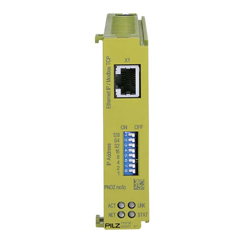
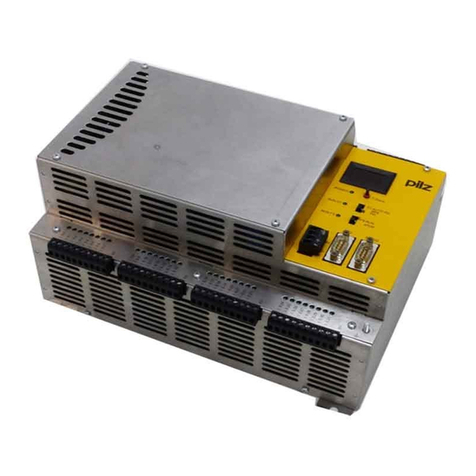
Pilz PSS Series User manual

-~
ARTISAN
®
~I
TECHNOLOGY
GROUP
Your definitive source
for
quality
pre-owned
equipment.
Artisan Technology
Group
Full-service,
independent
repair
center
with
experienced
engineers
and
technicians
on staff.
We
buy
your
excess,
underutilized,
and
idle
equipment
along
with
credit
for
buybacks
and
trade-ins
.
Custom
engineering
so
your
equipment
works
exactly as
you
specify.
•
Critical
and
expedited
services
•
Leasing
/
Rentals/
Demos
• In
stock/
Ready-to-ship
•
!TAR-certified
secure
asset
solutions
Expert
team
ITrust
guarantee
I
100%
satisfaction
All
tr
ademarks,
br
a
nd
names, a
nd
br
a
nd
s a
pp
earing here
in
are
th
e property of
th
e
ir
r
es
pecti
ve
ow
ner
s.
Find the Pilz PSS SB DI808 at our website: Click HERE

The spirit of safety.
Programmable Safety Systems
PSS-Range
PSS SB DI8O8
Operating Manual
Item No. 19 964-12
Artisan Technology Group - Quality Instrumentation ... Guaranteed | (888) 88-SOURCE | www.artisantg.com
All rights to this documentation are reserved by Pilz GmbH & Co. KG. Copies may be made
for internal purposes.
Suggestions and comments for improving this documentation ill be gratefully received.
The names of products, goods and technologies used in this documentation are registered
trademarks of the respective companies. Automation Workbench
®
, Pilz
®
, PIT
®
, PMI
®
,
PNOZ
®
, Primo
®
, PSS
®
, SafetyBUS p
®
are registered trademarks of Pilz GmbH & Co. KG.
Artisan Technology Group - Quality Instrumentation ... Guaranteed | (888) 88-SOURCE | www.artisantg.com

Operating Manual 1
Contents
Introduction 2
Validity of the documentation 2
Overview 2
Intended use 3
System requirements 3
CPU versions 3
System software versions 3
Functions 5
Inputs 5
Detecting signals at the inputs 5
Signal change behaviour 6
Outputs 7
Test pulse outputs 9
Schematic internal wiring diagram 10
Operation of the module on SafetyBUS p 10
Supply voltage 12
Display elements 13
Installation 14
Commissioning 15
Recommissioning 15
Faults 15
Check list for commissioning 16
Module configuration 17
Technical details 18
Changes in the documentation 21
PSS SB DI8O8
Artisan Technology Group - Quality Instrumentation ... Guaranteed | (888) 88-SOURCE | www.artisantg.com

PSS SB DI8O8
2Operating Manual
Introduction
This shortform explains the function and operation of the
decentralised input/output module PSS SB DI8O8.
The documentation is intended for instruction and should be retained for
future reference.
Validity of the documentation
The PSS SB DI8O8 documentation is valid from Version 2.1 onwards. It is
valid until new documentation is released. The latest documentation is
supplied with the unit.
Overview
The module provides 8 digital inputs, 8 digital outputs and 2 dedicated test
pulse outputs. The inputs are suitable for connecting single or dual-
channel safety-related input devices, with or without test pulses.
The inputs and outputs are driven from a SafetyBUS p-compatible PSS.
The module’s device address is established by setting the address switch
on the unit. Inputs on the module can be allocated to two I/O-groups.
There are 6 positive and 2 negative-switching 2 A outputs.
Two of the positive-switching outputs can be used in conjunction with two
negative-switching outputs (one each) to form two dual-pole outputs.
Individually, the negative-switching outputs can only be used for non-
safety-related applications, in which it is permitted to switch to earth.
All outputs are protected against short circuit, overload and excess
temperature. They are suitable for connecting both resistive and inductive
loads. Positive-switching outputs are suitable for connecting capacitive
loads of up to 1 µF.
The PSS SB DI8O8 requires two 24 V supplies with a common earth. The
“Supply” feeds the module electronics and dedicated test pulse outputs.
The “Load Supply” feeds the outputs.
The module is galvanically isolated from SafetyBUS p via optocouplers.
Artisan Technology Group - Quality Instrumentation ... Guaranteed | (888) 88-SOURCE | www.artisantg.com
Operating Manual 3
NOTICE
Before installing the module you should read and consider the “PSS
SB DI8O8 Installation Manual” and the “SafetyBUS p System
Manual”.
Intended use
The PSS SB DI8O8 is a decentralised input/output module which has
been designed for use as an input/output device on SafetyBUS p.
System requirements
CPU versions
The PSS SB DI8O8 is supported by all SafetyBUS p-compatible safety
systems in the PSS-range.
System software versions
The following system software is required in order to configure the module:
• PSS WIN-PRO from version 1.0.0
Artisan Technology Group - Quality Instrumentation ... Guaranteed | (888) 88-SOURCE | www.artisantg.com
PSS SB DI8O8
4Operating Manual
0
3
6
9
x 1
0
3
6
9
x 10
SB Address
1 = Supply
2 = Supply
3 = Load Supply
4 = Ground
^
^
^
^
Power
1234
1... Ground X2 ...
Load Supply
Supply
I/O-Group
Device
SB active
1... Load Supply X3 ...1... Power X1 ...4
PSS SB DI O
301 140
1... X4 ...
1... X6 ...
T
0
T
0
T
1
T
1
O
0
I
0
O
1
I
1
O
2
I
2
O
3
I
3
O
4
I
4
O
5
I
5
O
6
I
6
O
7
I
7
1... X7 ...1... X5 ...
X0
Group
O
0
I
0
O
1
I
1
O
2
I
2
O
3
I
3
O
4
I
4
O
5
I
5
O
6
I
6
O
7
I
7
129
1
3
2
4
5
6 7
810 11
7
1: Switch for setting the device address on SafetyBUS p
2: Labelling strip for the I/Os
3: SafetyBUS p interface
4: LEDs for operating status and supply voltage
5: Status LEDs for the I/Os
6: Terminal block for dedicated test pulses
7: Terminal blocks for I/Os
8: Connection terminal for the functional earth
9: Terminal block for the supply voltage
10: Terminal block for “Ground”
11: Terminal block for “Load Supply”
12: Terminal block for the functional earth
Artisan Technology Group - Quality Instrumentation ... Guaranteed | (888) 88-SOURCE | www.artisantg.com

Operating Manual 5
Functions
Inputs
The inputs are suitable for connecting single and dual-channel input
devices, with or without test pulses.
Input signals must show a “High” of 24 VDC (+15 ... +30 VDC) and a “Low”
of 0 VDC (-3 ... +5 VDC). All inputs have input filters.
Input status is transmitted to the CPU on the PSS master via SafetyBUS p.
Yellow LEDs indicate the status of the inputs. An LED lights up as soon as
a “1” signal is present at the input. If the supply is missing, the LEDs will
not light.
Diagnostic circuitry checks the function of the inputs, including the input
filter. If an error occurs, all the outputs in the affected I/O-group will be
switched off and the I/O-group will switch to a STOP condition. An error
telegram will then be stored on SafetyBUS p and the error will entered in
the PSS SB DI8O8 error buffer.
Where test pulses are not used, inputs with single-channel input devices
can be used in applications up to and including category 2 in accordance
with EN 954-1; in the case of dual-channel input devices, this extends to
category 3 applications. The device should be suitably wired to eliminate
the risk of a short circuit in the external wiring between the different inputs
and a short to the “Supply” or “Load Supply”.
Test pulses must be used for applications with single-channel input
devices above category 2 and applications with dual-channel input devices
above category 3.
Connection diagrams can be found in the “PSS SB DI8O8 Installation
Manual”.
Detecting signals at the inputs
To guarantee that a signal (“0“-Signal or “1“-Signal) is detected at an
input, it must be present for a certain period of time. This time must be
longer than the Event Timeout configured in the system software PSS
WIN-PRO. The presence of a signal will trigger a corresponding Event
Telegram.
The presence of a signal (“0” or “1” signal) will be ignored if it does not
exceed the pulse suppression time of 500 µs. In this case, no Event
Telegram will be sent.
Artisan Technology Group - Quality Instrumentation ... Guaranteed | (888) 88-SOURCE | www.artisantg.com

PSS SB DI8O8
6Operating Manual
Signal change behaviour
If a signal change occurs at an input, the module will send an Event
Telegram. The module must then wait for the acknowledgement telegram
(ACK) from the Master-LD before it can send a new Event Telegram.
If another signal change occurs while the module is waiting for the
acknowledgement telegram, the module's response will depend on the
configured signal change behaviour.
Two behaviour modes may be defined:
• “Default”:
The signal change is not registered
• “Fast”:
Each signal change is stored in a FIFO telegram buffer. If the
acknowledgement telegram arrives, the module will send an Event
Telegram from the FIFO telegram buffer for each signal change
detected.
"1"-Signal
"0"-Signal
t
1
t
1
t
t
2
U
t1: Pulse length for guaranteed signal detection for “1” or “0” signals
(> Event Timeout)
t2: Max. pulse length for pulse suppression on “1” or “0” signals
(500 µs)
Artisan Technology Group - Quality Instrumentation ... Guaranteed | (888) 88-SOURCE | www.artisantg.com

Operating Manual 7
Outputs
8 digital outputs are available on the module:
•O
0... O5are positive-switching (“Load Supply”) 2 A outputs
•O
6and O7are negative-switching (“Ground”) 2 A outputs
Positive-switching outputs are suitable for connecting resistive and
inductive loads of 2 A maximum. They have an integral discharge circuit
which means they are also suitable for connecting capacitive loads of up
to 1 µF. The use of higher capacitive loads will lead to an error (I/O-group
stopped). Negative-switching outputs are also suitable for connecting
resistive and inductive loads of 2 A maximum. However, individually these
outputs can only be used for non-safety-related functions.
Two dual-pole outputs can be configured: output O4can form a dual-pole
output with O6and output O5can form a dual-pole output with O7. If only
one dual-pole output is configured, this must be formed between O5/O7.
Dual-pole outputs are addressed via the address of the positive-switching
output (O4or O5). In principle it is also possible to wire outputs O0,O1,O2
or O3to a negative-switching output to form a dual-pole output; both
outputs would then have to be managed separately within the user pro-
gram.
If the PSS master sends a “1” signal to a positive-switching output via
SafetyBUS p, the PSS SB DI8O8 will supply approx. 24 VDC to the
relevant output, which will show high impedance at a “0” signal. Negati-
ve-switching outputs do the opposite. At a “1” signal, approx. 0 VDC will be
present at the output; at a “0” signal the output will show 24 VDC with high
impedance.
Output status is displayed via green LEDs. The corresponding LED will
light as soon as a “1” signal is present at the output.
Diagnostic circuitry tests the function of the outputs. The status of the
outputs is constantly compared with the process image of outputs.
Outputs that are switched on are switched off at regular intervals, to check
that the output transistors can be switched. Outputs that are switched off
are switched on at regular intervals in order to test the monitoring circuit. A
test will also be carried out to check for shorts between the outputs.
Artisan Technology Group - Quality Instrumentation ... Guaranteed | (888) 88-SOURCE | www.artisantg.com
PSS SB DI8O8
8Operating Manual
If an error occurs, all the outputs in the affected I/O group will be switched
off and the I/O-group will switch to a STOP condition. An error telegram
will then be stored on SafetyBUS p and the error will entered in the PSS
SB DI8O8 error buffer.
Outputs O0, O2, O4and O1, O3, O5have a common second shutdown
route. This means that, with single-channel operation, these outputs can
be used for applications up to and including category 3, in accordance with
EN 954-1. Please note that the second shutdown route is only tested when
the system switches from STOP to RUN.
A feedback loop must be used on safety-related applications. To achieve
category 4, dual actuators must be connected to two different outputs.
"1"-Signal
t
2
t
1
t
1
t
3
t
1
t
t
3
t
1
U
"0"-Signal
t1: Pulse length for switch-on test (200 µs)
t2: Repetition time under certain circumstances (6.5 ... 10 ms)
t3: Scan time for switch-on test (ca. 2 m)
WARNING!
When wiring an output with capacitance, you must be aware of the
following:
• An output that is switched off is tested by switching it on each cycle,
approx. once every 2 minutes.
• The pulse length of a switch-on or switch-off test is 200 µs
• Under certain circumstances, the switch on or switch-off test may be
repeated after 6.5 ... 10 ms.
• The internal resistance of an output is 0.35 Ohm
Failure to observe the values for wiring with capacitance may cause the
load to switch on unintentionally.
Artisan Technology Group - Quality Instrumentation ... Guaranteed | (888) 88-SOURCE | www.artisantg.com

Operating Manual 9
Test pulse outputs
The two test pulse outputs T0and T1are fed from the supply voltage and
are suitable for testing the wiring of input devices.
Only inputs which operate in accordance with the zero signal principle (on
switching off) are permitted for safety-related applications.
Test pulses are allocated to inputs via the configurator in the system
software.
Each test pulse has a maximum load capacity of 0.5 A.
If the plant is sensitive to the fast on/off switching of the output test,
individual outputs may be excluded from the test through the configuration.
NOTICE
In the case of outputs that are excluded from the output test, the PSS
checks that their switch status is correct but does not check their actual
ability to switch. This means that, under some circumstances, errors will
only be detected the next time the output switches on or off. In accordance
with EN 954-1, category 2 or higher can be achieved with such an output.
An output test can be performed in the user program in order to reduce
fault detection time. If the output is switched on, proceed as follows: at a
non-critical point in the program, switch the output off and
then on again for one PSS-cycle. Follow the process in reverse if the
output is switched off. If the output does not switch correctly, the error will
be detected and registered by the PSS SB DI8O8 operating system.
NOTICE
During commissioning, an error must be simulated for every safety-related
positive-switching output, in order to detect whether an output has been
incorrectly excluded from the output test, or to check whether the output
test programmed by the user is effective. Wait until the user program sets
the output to “1” (output’s LED will light) and then generate a short circuit
between the output and 24 V. The required error reaction should then
occur.
Artisan Technology Group - Quality Instrumentation ... Guaranteed | (888) 88-SOURCE | www.artisantg.com

PSS SB DI8O8
10 Operating Manual
Schematic internal wiring diagram
The diagram on page 12 shows a schematic internal wiring diagram of the
PSS SB DI8O8, showing the different output types, two shutdown routes
and galvanic isolation from SafetyBUS p, etc.
Operation of the module on SafetyBUS p
The connection to SafetyBUS p is made via a male 9-pin D-Sub
connector. Fibre-optic couplers from Pilz (like PSS SB SUB-D F0) can be
connected to the SafetyBUS p interface.
To enable the module to operate on SafetyBUS p, it must be given the
device address set via the configurator in the system software. Device
addresses 32dec ... 95dec are permitted if you are using the device in
conjunction with a Pilz PSS.
The configurator in the system software is also used to establish which I/O
groups the device belongs to.
The module can be divided into Section A and Section B. Section A and
Section B may belong to different I/O-Groups. The module itself can either
have Section A alone, or both Section A and Section B.
Outputs always belong to Section A. In the system software you can
configure a limit value to determine which section inputs will belong to:
those with a number below this limit will belong to Section A, those with a
higher number will belong to Section B.
The I/O addresses which the PSS master uses to address the I/Os are
established according to their membership of Section A or B and the
device address.
Under the device address in the process I/O image of the PSS master,
I/Os from Section A are addressed as device address and bit number 0 ...
7. Inputs from Section B are addressed under the device address as slot
number and bit number 16 ... 23. For example, if input I6from Section A is
reconfigured to Section B, the address will change from x.6 to x.22. The
offset for Section B is 16.
Example: Device address is 36, inputs I0to I4belong to Section A,
inputs I5to I7belong to Section B.
Formula for calculating Section B addresses:
Address of Ix= Device address .[(Input number Ix) + (Offset 16)]
Artisan Technology Group - Quality Instrumentation ... Guaranteed | (888) 88-SOURCE | www.artisantg.com

Operating Manual 11
T
1
I
0
5 V
24 V
DC
DC
CPU
(2-channel)
Test
O
7
O
6
O
3
O
2
O
1
O
0
I
7
Test
T
0
I
7
O
7
I
6
O
6
I
5
O
5
I
4
O
4
I
3
O
3
I
2
O
2
I
1
O
1
I
0
O
0
T
1
T
1
T
0
T
0
Ground
Load Supply
Supply
Supply
Ground
Load Supply
O
4
O
5
6,6 nF
3,3 nF 2,4 M
Schematic internal wiring diagram of the PSS SB DI8O8
Artisan Technology Group - Quality Instrumentation ... Guaranteed | (888) 88-SOURCE | www.artisantg.com

PSS SB DI8O8
12 Operating Manual
Example:
The device address is 36, inputs I0to I4belong to Section A,
inputs I5to I7belong to Section B.
So, taking I5 as an example: Address of I5= 36 .[5 + (Offset 16)] = 36.21
Output addresses: Input addresses:
O0→A36.00 I0→E36.00
O1→A36.01 I1→E36.01
O2→A36.02 I2→E36.02
O3→A36.03 I3→E36.03
O4→A36.04 I4→E36.04
O5→A36.05 I5→E36.21
O6→A36.06 I6→E36.22
O7→A36.07 I7→E36.23
Supply voltage
Two supply voltages can be connected to the PSS SB DI8O8: the “Supply”
feeds the module electronics and dedicated test pulse outputs, while the
“Load Supply” feeds the outputs. Both supply voltages have a common
earth.
The “Load Supply” must be connected, even if the outputs on the unit will
not be used. If it is not connected, Section A will remain in a STOP
condition (see section entitled “Operation of the module on SafetyBUS p”).
The advantage in separating the two supply voltages “Supply” and “Load
Supply” is best seen in the following example.
Several machines are secured by the same safety devices. Each of these
machines is assigned a PSS SB DI8O8 module. One power supply feeds
all the “Supply” modules and the general safety devices. Each machine
also has a separate supply voltage, “Load Supply”.
Each unit is configured so that I/Os that are specific to a particular
machine are combined into one I/O group. Inputs for the safety devices
are combined into one I/O group, which is general to all the DI808
modules.
If one of the machines is no longer required or develops a fault, this
machine can be switched off individually without affecting the safety
devices or stopping the other machines.
If the “Supply” fails or if a general safety device disengages, all the
machines will be switched off.
Section A
Section A
Section B
Artisan Technology Group - Quality Instrumentation ... Guaranteed | (888) 88-SOURCE | www.artisantg.com

Operating Manual 13
Display elements
LEDs for status display
Each input and output is assigned an LED for status display.
If the input or output is high, the corresponding LED will light. If it goes low,
the LED will go out.
LED “Supply”
Indicates that the supply is present.
LED “Load Supply”
Indicates that the load supply is present.
LED “Device”
This dual-coloured LED indicates the status of the device.
• Red: a device error has occurred. The device error may affect one or
both of the I/O groups configured on the module.
• Flashing red: a periphery error has occurred.
• Green: the module is operating without error.
• LED off: a system error is preventing the module from starting up.
LED “SB active”
Indicates a connection between the module and the management device.
• Green: Successfully connected to management device
• LED off: no connection to SafetyBUS p (faulty wiring or management
device not in operation)
• LED flashing: Connection made to SafetyBUS p, but the management
device does not recognise the module (invalid device address or
configuration)
LED “I/O Group”
Indicates the status of the I/O groups configured on the module.
• Green: all the I/O groups configured on the module have “RUN” status
• LED off: all the I/O groups configured on the module have “STOP” status
• LED flashes: one of the I/O groups configured on the module has
“STOP” status
Artisan Technology Group - Quality Instrumentation ... Guaranteed | (888) 88-SOURCE | www.artisantg.com

PSS SB DI8O8
14 Operating Manual
0
3
6
9
x 1
0
3
6
9
x 10
SB Address
1 = Supply
2 = Supply
3 = Load Supply
4 = Ground
^
^
^
^
Power
1234
1... Ground X2 ...
Load Supply
Supply
I/O-Group
Device
SB active
1... Load Supply X3 ...1... Power X1 ...4
PSS SB DI O
301 140
1... X4 ...
1... X6 ...
T
0
T
0
T
1
T
1
O
0
I
0
O
1
I
1
O
2
I
2
O
3
I
3
O
4
I
4
O
5
I
5
O
6
I
6
O
7
I
7
1... X7 ...1... X5 ...
X0
160 (6.30")
65 (2.56")
15
(0.59")
60 (2.36")
Group
O
0
I
0
O
1
I
1
O
2
I
2
O
3
I
3
O
4
I
4
O
5
I
5
O
6
I
6
O
7
I
7
Free space for rail-
mounting and for
ventilation
Recommended
free space
for wiring
Installation
Dimensions in mm ("):
H x W x D: 140 x 170 x 65 (5.51 x 6.69 x 2.56)
The module can be attached to a 35 mm DIN-rail (top hat rail) or can be
screwed on to mounting plate using fixing bolts (order no. 311 068).
To affix the module on to a mounting plate, drill 2 x M4 holes (internal
thread) in the mounting plate, as shown in the above diagram (tolerance:
± 0.2 mm/0.01").
Installing the PSS SB DI8O8, dimensions stated in mm (")
Artisan Technology Group - Quality Instrumentation ... Guaranteed | (888) 88-SOURCE | www.artisantg.com

Operating Manual 15
Commissioning
General guidelines are given below, but you should always refer to the
“PSS SB DI8O8 Installation Manual” (this is part of the “Safety BUS p”
System Manual and is also enclosed with every Safety BUS p-compatible
PSS):
• Install the module
INFORMATION
If the module is attached to an earthed DIN rail, this will automatically
cover the module's functional earth requirements.
• Wire the inputs and outputs
• Connect the module to SafetyBUS p and set the device address
• Connect the supply voltage.
•NOTICE
Every safety-related positive-switching output should undergo an error
simulation: wait until the user program sets the output to “1” (output’s
LED will light) and then generate a short circuit between the output and
24 V. The required error reaction should then occur. This is the only way
to check whether an output has been incorrectly excluded from the
output test and whether the output test that has been programmed is
effective.
Recommissioning
NOTICE
If the device has to be recommissioned you may experience errors when
inserting the terminal blocks, as these are not designed to be exchanged.
To ensure such errors are eliminated, always carry out a function test
when recommissioning.
Faults
If a module is defective or there is a wiring error, all the outputs in the
affected I/O group will be switched off and the I/O-group will switch to a
STOP condition. An error telegram will then be stored on SafetyBUS p and
the error will entered in the PSS SB DI8O8 error buffer.
An error message will appear on the PSS master’s display. The error stack
display in the system software can be used to locate the error (see
“SafetyBUS p System Description”).
Artisan Technology Group - Quality Instrumentation ... Guaranteed | (888) 88-SOURCE | www.artisantg.com

PSS SB DI8O8
16 Operating Manual
Check list for commissioning
Confirm
during
Fill out when designing the plant and its configuration: commissioning:
Information on the device address Address set
Device
address
Output Designed Safety- Excluded Required reaktion in Error simulated
as dual- related from case of error for safety-related
pole output output output1)
output test
yes no yes no yes no
O0
O1
O2
O3
O4
O5
O6
O7
Date:...................................... Date:....................
Signed:.............................. Signed:............
1) Wait until the user program sets the output to “1” (output’s LED will light) and then generate a short
circuit between the output and 24 V. The required error reaction should then occur.
Artisan Technology Group - Quality Instrumentation ... Guaranteed | (888) 88-SOURCE | www.artisantg.com
Operating Manual 17
Module configuration
The procedure for configuring SafetyBUS p and the PSS SB DI8O8
module is described in the online help of the PSS WIN-PRO system
software.
Artisan Technology Group - Quality Instrumentation ... Guaranteed | (888) 88-SOURCE | www.artisantg.com
Other manuals for PSS Series
9
This manual suits for next models
1
Table of contents
Other Pilz Safety Equipment manuals

Pilz
Pilz PNOZ mo5p User manual

Pilz
Pilz PSS Series User manual

Pilz
Pilz PSEN cs3.1a User manual

Pilz
Pilz PSEN op2H-s-30 1 Series User manual

Pilz
Pilz 19 964-12 User manual

Pilz
Pilz PIT si2.1 User manual

Pilz
Pilz PSEN op4F/H A Series User manual

Pilz
Pilz PNOZ e1.1p User manual

Pilz
Pilz PSEN opII3B Series User manual

Pilz
Pilz PNOZ ms2p TTL User manual