FCARACTERISTIQUES TECHNIQUES
- PORTÉE MAX de fonctionnement 80m (avec bonnes conditions atmosphériques)
- ALIMENTATION 12÷24 V ac/dc
- ABSORPTION 100mA maximum
- ÉMETTEUR modulé avec diode infrarouge.
- LED VERTE allumée, signale que le émetteur est alimenté.
- LED ROUGE allumée, signale que le recepteur est aligné. (N.B. le tarage ayant
été effectué, elle s’éteint au moment où un’obstacle s’interpose).
- PORTÉE DU RELAIS 1A - 30Vdc
- DEGRÉ DE PROTECTION IP54
N.B. La portée peut être reduite en présence de brouillard, pluie, poussière, etc..
INSTRUCTIONS DE MONTAGE ET DE REGLAGE
Encastrer ou fixer les carters sur les piliers ou potelets à une hauter d’environ 40 ou 60 cm du
sol et à une distance de 10 cm par rapport à l’alignement du portail fermè, et dans le cas d’un
portail ouvrant «à battant», les positioner à 10 cm des vantaux ouverts.
Installer le récepteur dans une zone ombragée ou dans une position où le soleil ne tape pas
horizontalement.
Quoi qu’il en soit, il est vivement recommandé de positionner les Photocellules à la même
hauteur, en veillant à ce qu’elles soient parfaitement alignées.
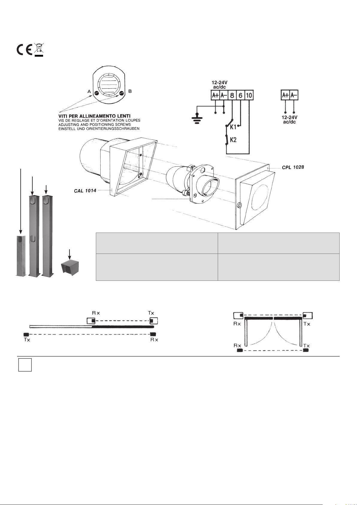
Dans le cas de montage d’un double barrage de cellules, les positionner comme sur le Fig. 1 et
2.
En cas de volets sur portails à battants, la distance de 10 cm doit être mesurée en position
portes ouvertes.
REGLAGE ET ALIGNEMENT.
1) Enlever les caches fumés d’e l’émetteur et du récepteur.
2) Pour diriger les loupes dévisser ou visser les vis A et B du récepteur et de l’emetteur jusqu’a
ce que le LED ROUGE du RECEPTEUR s’allume.
3) Lorsque le réglage est fait, remonter les caches et vérifier si, en interposannt un obstacle
devant la cellule, celle-ci donne l’impulsion qui lui est demandée.
N.B. Si le voyant lumineux du récepteur reste allumé, il est probable qu’il existe des
problèmes au niveau du réseau d’alimentation. Connecter à la terre le pôle
d’alimentation dénommé “A/D-”. Veiller à ne créer aucun court-circuit lorsque les
phases d’alimentationt sont inversées !
RÉFÉRENCES RÉGLEMENTAIRES POUR PORTAILS ET VANTAILS AUTOMATIQUES
L’installateur ne devra procéder à l’installation des Photocellules qu’après s’être assuré
de l’existence d’une ultérieure protection principale, conformément aux spécification du
paragraphe 5.1.3 de la norme EN12453.
RIB DÉCLINE TOUTE RESPONSABILITÉ POUR LES ÉVENTUELS DOMMAGES DÉRIVANT D’UN USAGE
IMPROPRE, ERRONÉ OU IRRAISONNÉ.
GB TECHNICAL FEATURES
- MAX. OPERATING RANGE 80 m (in good weather conditions)
- SUPPLY VOLTAGE 12÷24 V ac/dc
- POWER 100mA max.
- TRANSMITTER modulated with infrared diode.
- GREEN LED when lit this signals that the transmitter is fed.
- RED LED when lit this signals that the receiver is aligned (N.B. when you have
finished calibrating, this goes off when there are obstacles in the way).
- RELAY 1A - 30Vdc
- PROTECTED TO IP54
Note: Range may be reduced in the presence of fog, rain, dust, etc.
SETTING AND MOUNTING INSTRUCTIONS
Wall or fit the external casings on the pillars or columns at approximately 40-60 cm from the
floor and 10 cm in distance from the conveyance or deflection area or immediately next to the
space taken by the safety strip.
Install the receiver in a shaded area or where horizontal rays of sunlight cannot reach it.
Always install the photocells at the same height and make sure they are well aligned.
When mounting the double couple of photoelectric cells, position them as shown in Fig. 1 and
2.
In case of leaf gates, 10 cm distance must be calculated when the gate leaves are open.
ASSEMBLY INSTRUCTIONS
1) Remove the transmitter and receiver’s screens.
2) To position the lenses, loose or tighten screws A and B of Transmitter and Receiver until
when the Receiver’s RED LED is on.
3) When setting is completed, refit the screws and make sure that when an obstacle is in the
way, the contact is made as required.
Note: If the receiver LED remains on the power supply may be disturbed. Earth the “A/D-”
power input pole. Make sure not to create short circuits when inverting the power
input phases!
REFERENCE LEGISLATION FOR POWER-OPERATED DOORS AND GATES
Fitters must make sure that the photocells are only installed together with another primary
safety device, as specified in point 5.1.3. of European standard EN 12453.
RIB DECLINES ALL LIABILITY FOR DAMAGE CAUSED BY IMPROPER, INCORRECT OR IRRESPONSIBLE
USE.
DTECHNISCHE MERKMALE
- MAXIMALER ABSTAND 80 m (bei guten atmosphärischen Bedingungen)
- SPEISUNG 12÷24 V ac/dc
- AUFNAHME 100mA maximal
- SENDER MODULIERTER mit Infrarot-Diode.
- GRÜNE LED leuchtet sie auf, so ist der Sender gespeist.
- ROTE LED leuchtet sie auf, so ist der Empfäger gespeist (Bitte beachten Sie: Wenn das
Gerät geeicht ist, schaltet sich diese Anzeige aus, sobald ein Hindernis im
Weg ist)
- RELAIS 1A - 30V dc
- SCHUTZGRAD IP54
Anmerkung: Die Reichweite kann bei Nebel, Regen, Staub usw. verringert werden.
MONTAGE - UND EICHUNGSANWEISUNGEN
Die Außenbehälter auf Pfeilern oder Säulen an einer Höhe von ca. 40-60 cm vom Boden und an
einer Entfernung von 10 cm vom Forderungs - oder Zerdrückungsgebiet oder sofort nach dem
Raumbedarf von einer evtl. Kontaktleiste befestigen.
Der Empfänger muss im Schatten, bzw. an einer von horizontalen Sonnenstrahlen geschützten
Lage eingebaut werden.
Es ist in jedem Fall empfehlenswert, die Zellen auf gleicher Höhe, in einer Reihe zu
positionieren.
Im Falle von Montage von einem doppelten Paar von Photozellen, Abb. 1 und 2 positionieren.
Im Falle von drehenden Flügeln, soll der ‘abstand von 10 cm mit geöffnenten Flügeln gemessen
werden.
EICHUNG UND FLUCHTUNG
1) Die dunkle Maske des Senders und des Empfängers entfernen.
2) Um die Linsen zu orientieren, die Schrauben A und B des Senders und des Empfängers
lockern oder einschrauben, bis die ROTE LED des Empfängers einschaltet.
3)Am Ende der Eichung, die Masken wieder montieren und prüfen, daß, wenn man ein
Hindernis vor der Photozelle zwischenlegt, diese den gewünschten Kontakt gibt.
Anmerkung:Wenn die LED des Empfängers eingeschaltet bleibt, ist es möglich, dass
Störungen im Versorgungsnetz vorliegen. Es wird empfohlen, den
Versorgungspol mit Namen “A/D-” zu erden. Darauf achten, keine Kurzschlüsse
zu erzeugen, wenn die Versorgungsphasen invertiert werden!
BEZUGSNORMEN FÜR AUTOMATISCHE TÜREN UND GITTERTÜREN
Der Installateur muss sich vergewissern, dass der Einbau ausschließlich bei Vorhandensein
einer zusätzlichen Haupt-Sicherheitseinrichtung, gemäß Vorschrift EN12453, Pkt. 5.1.3,
vorgenommen wird.
RIB IST NICHT FÜR EVENTUELLE SCHÄDEN VERANTWORTLICH; DIE AUF EINE UNVEREINBARE,
FALSCHE ODER UNVERNÜNFTIGE ANWENDUNG ZURÜCKZUFÜHREN SIND.
Cod. CET1149 - 042021 - Rev. 18
AUTOMATISMI PER CANCELLI
AUTOMATIC ENTRY SYSTEMS
R.I.B. S.r.l. - Via Matteotti, 162 - 25014 Castenedolo - Brescia - Italy
Dichiariamo sotto la nostra responsabilità che la
fotocellula F97I è conforme alle seguenti norme e
Direttive:
Le fabricant certifie en engageant sa seule
responsabilité que les produit
F97I
est conforme aux
Normes et Directives ci-dessous:
We declare, on our own responsibility, that operating
devices of
F97I
comply with the following standards
and Directives:
Wir erklären unter unserer Verantwortung, dass
die
F97I
mit den folgenden Normen und Richtlinien
übereinstimmen:
EN 12978:2003+A1:2009
EN 13241:2016
EN 13849-1:2015 PL»c» CAT.2
EN 55014-1:2019
EN 55014-2:2015
EN 60335-1:2016
EN 60335-2-103:2016
EN 61000-3-2:2019
EN 61000-3-3:2013+A1:2019
EN 61000-6-1:2019
EN 61000-6-2:2019
EN 61000-6-3:2013
EN 61000-6-4:2020
Come richiesto dalle seguenti Direttive:
Conformément aux Directives:
As is provided by the following Directives:
Wie es die folgenden Richtlinien verfügen:
2014/30/UE
2014/35/UE
(Bosio Stefano - Legal Representative)
Castenedolo, 01-11-2020
Scarica questo manuale sul tuo cellulare
Téléchargez ce manuel sur votre mobile
Download this manual on your mobile
Laden Sie dieses Handbuch auf Ihr Handy herunter
Descarga este manual en tu móvil