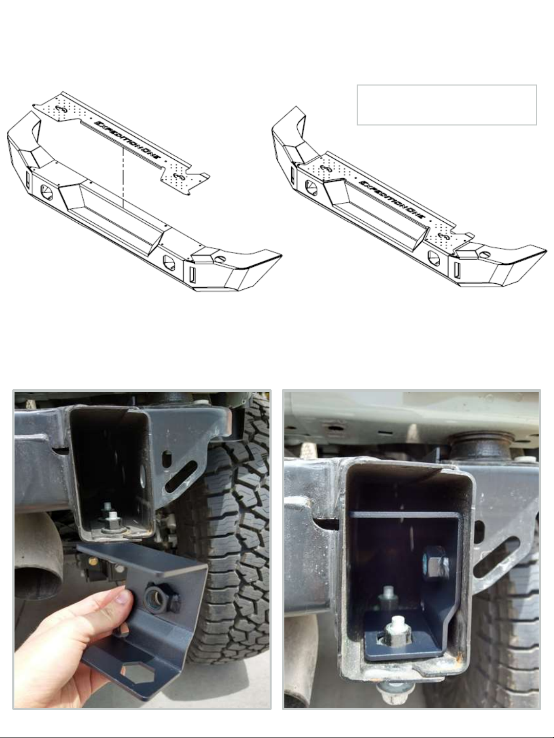
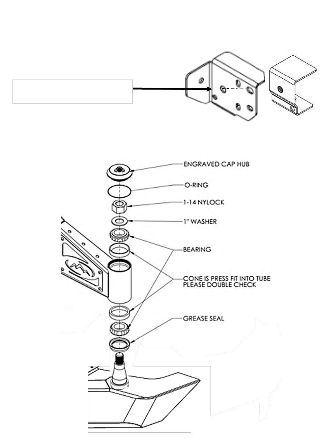
Expedition One BRONCO STC REAR 2021 Plus User manual

INSTALLATION GUIDE
2 0 2 1 + B R O N C O S T C R E A R

NOTE
We highly recommend customers wait until they have the product in hand to schedule installations. All cancellations are
required in writing and will incur a 10% re-stock fee and any applicable packaging and shipping fees. Please review terms and
conditions for details.
* A narrow wheel with an extreme positive offset and a very wide tire may not work with the standard tire mount
*Sensor holes are included however they are not guaranteed to work.
This product contains chemicals known to the state of California to cause birth defects or other reproductive harm. For more
information go to www.p65warnings.gov

1/4”-20 X 3/4” BUTTON HEAD 10
1/4”- 20 NYLOC NUT 10
TREADPLATE & HARDWARE
LICENSE PLATE MOUNT LUG BRACKET
LICENSE PLATE MOUNT HARDWARE
LUG –12 X 1.5 3
BRONZE BUSHING 4
8 – 32 X 1/2” BUTTON HEAD 2
8 –32 NYLOC NUT 2
M12 –1.5 X 45MM HEX CAP 2
M12 –1.5 X 50MM HEX CAP 2
LICENSE PLATE LIGHT 1
1/4”-20 X 3/4” HEX CAP BOLT 2
1/4”- 20 NYLOC NUT 2
1/4” USS WASHER 2
5/16”-18X3/4” CARRIAGE 1
5/16” – 18 NYLOC NUT 1
5/16” USS WASHER 2
HARDWARE
MOUNTNG BRACKETS NUT RETAINER BRACKETS
REAR BUMPER HARDWARE
1/2” – 13 X 1 1/4” HEX CAP BOLT 10
1/2” – 13 NYLOC NUT 10
1/2” USS WASHER 20
5/8” – 11 X 1 1/2” HEX CAP BOLT 2
5/8” USS WASHER 2
SENSOR BEZELS

STC SWING ARM + LOGO PLATE
STC COUPLER
DOOR PLATE
TIRE CARRIER
TIRE CARRIER MOUNT
CAMERA BRACKET ALUMINUM ROUND SPACER
KEY HOLE SPACER
STC HUB COVER 1
STC HUB ORING 1
STC BEARING UPPER 1
STC BEARING LOWER 1
STC GREASE SEAL 1
PACKET ANTI SEIZE 1
BEARING KIT
BUMP STOP 2
BUMPER STOP SPACER/SHIM 2
M8 –1.25 X 35 SOCKET CAP 2
M8 –1.25 NYLOC NUT 2
BUMPSTOP KIT

REAR BUMPER HARDWARE
1/4” – 20 X 3/4” BUTTON HEAD 4
1/4” – 20 NYLOC NUT 4
1/4” X 0.625 SAE WASHER 4
3/8” – 16 X 1/4” HEX CAP BOLT 4
3/8” – 16 X 4” HEX CAP BOLT 1
3/8” – 16 NYLOC NUT 4
3/8” – 16 NYLOC JAM NUT 1
3/8” X 0.812 SAE WASHER 8
1/2” – 13 X 1 1/4” HEX CAP BOLT 3
1/2” – 13 X 3 1/2” HEX CAP BOLT 1
1/2” – 13 X 4 1/2” HEX CAP BOLT 1
1/2” – 13 NYLOC NUT 5
1/2” X 1.125 SAE WASHER 8
1” – 14 NYLOC NUT 1
1” X 2.000 WASHER 1
M6 –1.00 X 25MM BOLT 2
M6 –1.00 NYLOC NUT 2

INSTALLATION
REMOVE OEM BUMPER
- Disconnect the wiring loom on the drivers side.
- Remove the frame bolts (Circled) to remove the bumper.
- Check for any remaining hardware or connections before removing the bumper.
- Keep OEM hardware for reinstallation on the new bumper
- Remove the spare tire and OEM tire mount.
- Disconnect the camera and other remaining hardware from the rear door.
1

REMOVE THE BUMPER
Remove the bumper from the vehicle.
2
OEM BUMPER HARDWARE REMOVAL
Remove the wiring loom and sensors by removing any clips or mounts located on the inside of
the bumper
3
PARKING SENSOR INSTALLATION (IF APPLICABLE)
Place the OEM wiring harness into the new bumper, threading the wiring through so that
connectors match there respective positions. Make sure the wiring harness connector is
located on the correct side of the vehicle. Reattach all 4 parking sensors to the provided
sensor bezels. Avoid placing the wiring harness near mounting holes and visible cutouts.
Mount any aftermarket lights at this time.
NOTE - The license plate will be relocated to the tire or another place of your choosing. The wiring for
this can be extend at this point. We do not provide any hardware or parts for the wiring.
4

TREAD PLATE INSTALLATION
Mount the tread plate as shown using the provided 1/4”
5
1/4”-20 X 3/4” BUTTON HEAD 10
1/4”- 20 NYLOC NUT 10
NUT RETAINER BRACKET LOCATION
Place the provided nut retainer brackets inside the frame as shown.
6

MOUNTING BRACKET
Attach the mounting brackets to the vehicle as shown using the provided 1/2” hardware and
bottom OEM hardware. Leave all hardware loose for adjustment, this just to hold the bracket
in place for mounting the bumper
7
1/2” – 13 X 1 1/4” HEX CAP BOLT 2
1/2” – 13 NYLOC NUT 2
1/2” USS WASHER 4
OEM HARDWARE 4
INSTALLATION OF THE REAR BUMPER
Mount the bumper as shown.
8

5/8” – 11 X 1 1/2” HEX CAP BOLT 2
5/8” USS WASHER 2
Use the 5/8” hardware to mount the bumper to both the nut retainer and mounting bracket.
Leave all hardware loose for adjustment, this just to hold the bumper in place for mounting
the swing arm. The bumper will rotate on this axis, be mind full it may pitch into the body.
SWING ARM MOUNTING

SWING ARM INSTALLATION
Rotate the bumper up and out to allow clearance for attaching the swing arm. Place the arm
on the spindle and move the arm until it falls into place. Once in place, rotate the bumper back
into position. Insert the top bearing in the hub.
9BOTTOM BEARING AND GREASE SEAL
Grease Bearings using marine-based lithium grease. Install the first bearing into the bottom
of the swing arm. Ten place a grease seal inside the bottom of the arm.
10

SWING ARM MOUNTING
Place the washer into the swing arm, then insert the nut over the bolt. Tighten the nut using a
36mm socket. Don’t over tighten to prevent binding.
11
HUB COVER
Ensure that the inside of the spindle and its contents are coated thoroughly. Check that the hub
cap has a O-ring and spread anti-seize around the cap thread before tightening on the arm.
12
USE 36MM SOCKET FOR NUT
Always be sure to use the anti-seize when installing and
re-installing your hub cover, otherwise removal will be
very difficult! Remove your hub cover and check inside
your hub assembly regularly. If you live in a dry climate
and of-road a “standard” amount, we would
recommend you check your hub assembly at least once
per year. If you live in a wet climate, humid climate, or a
climate with extremes, we would recommend you
check your hub assembly quarterly or with season
changes. Climates with heavy salt content are some the
harshest conditions on your components and may need
to be checked more frequently. Regrease as needed.

1/2” – 13 X 1 1/4” HEX CAP BOLT 8
1/2” – 13 NYLOC NUT 8
1/2” USS WASHER 16
Place the swing arm out of the way or safely place against something while continuing to
mount the bumper. Center the bumper with the vehicle and align gaps between the body and
bumper to your preference before mounting. Mount the front bumper using the supplied
1/2” hardware as shown below. Use the 5/8” hardware to mount the bumper to both the
nut retainer and mounting bracket. Leave all hardware loose for adjustment.
13 INSTALLATION OF REAR BUMPER

Attach the bump stops to door plate locations as shown below using the provided hardware.
Mount the door plate using the original OEM hardware. Leave hardware loose for adjustment.
14
Connect the swing arm and door as shown using the provided hardware and coupler with spacers.
15
Overall, you want the carrier to be snug against the rear door. The coupling joints are the key to this.
With the rear gate and carrier in the closed position, you can now start the adjustment of the
coupling joints. You may need to adjust the height of the coupling joints with the spacers so it
doesn’t bottom-out. NOTE: The door and the carrier swing at slightly different angles. With the tire
carrier installed and the door in the closed or almost closed position, the bump-stop needs to be
making contact with the door. Adjust the coupling so that when the door is open and closed the
bump-stop initially contacts the door mount plate on the tail gate (this may need to be adjusted
later when the spare tire is mounted to the carrier). The door will naturally want to raise up due to
its design and lack of tire mounted on it. Adjust the bumper pitch and height in combination of
getting the door to align. You want the carrier to shut and be snug but not overly tight. If the door
swings with little or no binding the installation can now be completed. Check the swing of the arm,
if there is little or no binding you may finish the install and tighten all hardware.
Recommended: use water resistant grease in fitting the coupler bolts.
DOOR PLATE MOUNTING
SWING ARM ATTACHEMENT
1/2” – 13 X 3 1/2” HEX CAP BOLT 1
1/2” – 13 X 4 1/2” HEX CAP BOLT 1
1/2” – 13 NYLOC NUT 2
1/2” X 1.125 SAE WASHER 4
ALUMINUM ROUND SPACERS 2

NOTE –My require the adjustment of the door latch in some
cases should the door still lift. Loosen and adjust the latch to as
needed. Bumper pitch and height may be a combination in
getting the door to align. Retighten once the door properly
swings with the arm attached.
DO NOT OVER TIGHTEN THE COUPLER - Check that the door
and swing arm are not binding and are adjusted accordingly.
Some movement in the carrier is normal as both the door and
swing arm are separate items. Do not over tighten mounts or
modify items to compensate for this. Check bearings and seal
regularly for maintenance.

Remove the OEM plastic camera housing from the original spare tire mount. Once removed,
cut or bend the tabs and old mounts from the camera base for install into the new relocation
bracket. The top portion will need to be trimmed to fit behind the new bracket
16 CAMERA RELOCATION

Mount the camera to the plate using the OEM hardware and provided key hole spacers inserted into
the tire mount.
Attach the tire mount to the swing arm door as shown below. Mount using the provided 3/8”
and 1/2” hardware.to the highest mounting position.
17 TIRE MOUNT

18 SPARE TIRE
Mount the spare and install the license plate relocation in the next step if desired
NOTE - A narrow wheel with an extreme positive offset or a very wide tire may not work with
the standard tire mount. Aftermarket fitments vary and may not match the provided pattern
or studs sizes.

19 LICENSE PLATE RELOCATION OPTION
Assemble the license plate relocation as shown using the provided hardware.
NOTE - The license plate can be relocated to the tire or another place of your choosing. We do not
provide any hardware or parts for the wiring.
M12X1.5 HEX BOLT

20 TIGHTEN ALL HARDWARE
Check that all hardware is tightened including all brackets and mounting locations.
21 RECONNECT WIRING HARNESS
Reconnect the parking sensor wiring harness to the vehicles electronics and secure all loose
wiring. Check that everything is working and adjust if needed before driving on the road.
ADDITIONAL LINKS
https://www.exp-one.com/wp-content/uploads/2016/10/Proper-Care-and-Maintenance.pdf
https://www.exp-one.com/wp-content/uploads/2016/10/Paint-touch-up-instructions.pdf
https://www.exp-one.com/wp-content/uploads/2018/02/Exp-One-2016-TC-word-doc.pdf
TIGHTEN ALL HARDWARE AFTER EVERYTHING IS INSTALLED ON THE VEHICLE.
CHECK AND RETIGHTEN ALL HARDWARE AFTER THE FIRST 100 MILES AND AFTER OFF ROADING.
CHECK REGULARLY
Other Expedition One Automobile Accessories manuals

Expedition One
Expedition One Mule Front Bumper User manual

Expedition One
Expedition One EXP911 User manual

Expedition One
Expedition One GERI GEN 2 User manual

Expedition One
Expedition One JK 3rd Brake Light User manual

Expedition One
Expedition One HI-LIFT/PULL PAL GEN 2 User manual

Expedition One
Expedition One EXPDSTC01 User manual

Expedition One
Expedition One NATO CAN GEN 3 User manual

Expedition One
Expedition One NATO CAN GEN 2 User manual

Expedition One
Expedition One DSTC User manual

Expedition One
Expedition One 4RFJ-LADDER User manual