manuals.online logo
Brands
  1. Home
  2. •
  3. Brands
  4. •
  5. Extron electronics
  6. •
  7. Microphone System
  8. •
  9. Extron electronics VLP 202 User instructions

Extron electronics VLP 202 User instructions

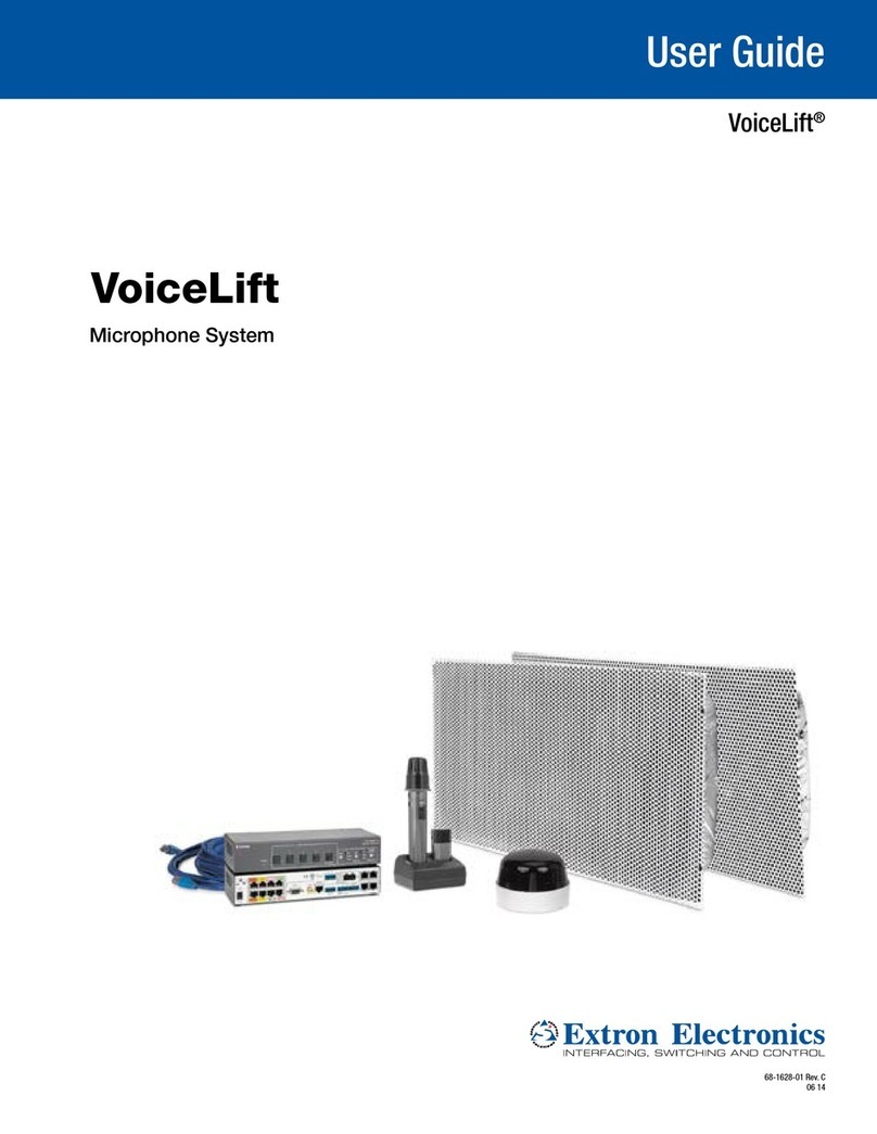
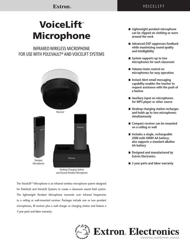
This guide provides instructions for an experienced installer to set up, install, and
connect the Extron VLP 202 VoiceLift Compact Pendant Microphone or VLH 102 VoiceLift
Handheld Microphone, the VLC 202 Charging Station and the VLR 102 Receiver in a system
with a PVS 405D PoleVault Digital Switcher.
Setting Up the VLP 202 and VLH 102 Microphones
1. Set the channel using the rotary switch. Aand C= 2.3 MHz; Band D= 2.8 MHz. For the VLH 102, remove the battery cover
to access this switch.
NOTE: Each microphone must be on a different frequency. On the pendant microphone, set the channel to Cor Dto
disable the volume buttons (the handheld microphone has only channels Aand B, and its volume cannot be disabled).
2. For pendant microphones only, apply the appropriate sticker (provided) to identify the microphone.
3. Remove the battery cover and insert a AA battery. If necessary, replace the battery cover and
charge the rechargeable battery (see “Installing the VLC 202 Charging Station,” below).
4. For pendant microphones only, attach the lanyard to the microphone as follows:
a. Press the lanyard into the guides on the sides of the lanyard clip
(see the VoiceLift System with PVS 405D Installation Guide for details).
b. Press the top of the microphone clip to lift it.
c. Slide the lanyard lock under the clip and release the clip (see the illustration at right).
d. Place the lanyard around your neck and slide the lanyard through the lock until the microphone
is positioned approximately 4 inches (10.2 cm) below your chin.
5. Turn the microphone on by sliding the power switch up.
6. Speak in a normal tone of voice. Do not block the microphone port or grille opening.
7. Adjust the volume if necessary.
8. Ensure that a direct line of sight exists from the
microphone to the receiver (required for proper
operation). Do not block the IR transmitter window.
Installing the VLC 202 Charging Station
To install the charging station (see the illustration at right):
1. Plug the wall charger (5 V, 1 A) into a wall outlet.
2. Connect the wall charger cable to the charging station
power jack.
3. Place the microphone in one of the slots in the charger.
The charge is complete when the microphone LED
turns green (this can take up to 5 hours).
Guides
1
Extron Headquarters
+800.633.9876 Inside USA/Canada Only
Extron USA - West Extron USA - East
+1.714.491.1500 +1.919.850.1000
+1.714.491.1517 FAX +1.919.850.1001 FAX
Extron Europe
+800.3987.6673
Inside Europe Only
+31.33.453.4040
+31.33.453.4050 FAX
Extron Asia
+65.6383.4400
+65.6383.4664 FAX
Extron Japan
+81.3.3511.7655
+81.3.3511.7656 FAX
Extron China
+86.21.3760.1568
+86.21.3760.1566 FAX
Extron Middle East
+971.4.299.1800
+971.4.299.1880 FAX
Extron Korea
+82.2.3444.1571
+82.2.3444.1575 FAX
Extron India
1800.3070.3777
(Inside India Only)
+91.80.3055.3777
+91.80.3055.3737 FAX
© 2014 Extron Electronics All rights reserved. All trademarks mentioned are the property of their respective owners. www.extron.com
CAUTION:
• Do not replace the battery with an incorrect type.
• Ne pas remplacer la pile par le mauvais type de pile.
ATTENTION:
• Do not charge alkaline batteries.
• Ne rechargez pas les piles alkalines.
• Dispose of used batteries according to the instructions provided on the
battery packaging.
• Débarrassez-vous des piles utilisées selon les instructions du fabricant.
NOTE: The microphone can be left to charge for extended periods. It should
not be turned off while charging.
Installing the VLR 102 Receiver
To install the VLR 102 IR Receiver in a drop ceiling:
1. In the ceiling tile, cut a hole 2 to 3 inches (50 to 76 mm) in
diameter.
2. If necessary, separate the receiver housing from the base (see
the VoiceLift Microphone System User Guide, available at
www.extron.com).
3. Align the center of the receiver housing with the hole in the
ceiling tile.
4. Insert the mounting screw through the receiver housing and
the hole in the ceiling tile.
5. Attach the provided Z-bracket to the end of the screw on the
back side of the ceiling tile. Replace the ceiling tile.
6. Pull a shielded CAT5 cable to the receiver location, and
connect one end of the cable to the RJ-45 jack (labeled OUT)
on the receiver base.
7. Align the arrow on the dome tab with the raised arrow on the
edge of the housing. Rotate the dome clockwise until the
arrow on the tab aligns with the raised dot on the housing.
8. Connect the other end of the shielded CAT5 cable to the
VoiceLift RJ-45 connector of the PoleVault switcher.
2
68-2548-50 Rev. B
05 14

This manual suits for next models

1

Other Extron electronics Microphone System manuals

Extron electronics VoiceLift User manual

Extron electronics

Extron electronics VoiceLift User manual

Extron electronics VoiceLift VLP 202 User manual

Extron electronics

Extron electronics VoiceLift VLP 202 User manual

Extron electronics VoiceLift User manual

Extron electronics

Extron electronics VoiceLift User manual

Extron electronics VoiceLift User manual

Extron electronics

Extron electronics VoiceLift User manual

Extron electronics MTP A/V Series User manual

Extron electronics

Extron electronics MTP A/V Series User manual

Extron electronics VoiceLift User manual

Extron electronics

Extron electronics VoiceLift User manual

Extron electronics VoiceLift User manual

Extron electronics

Extron electronics VoiceLift User manual

Extron electronics VoiceLift Pro VLS 3001 User manual

Extron electronics

Extron electronics VoiceLift Pro VLS 3001 User manual

Extron electronics VoiceLift Microphone User manual

Extron electronics

Extron electronics VoiceLift Microphone User manual

Extron electronics VoiceLift Pro Microphone EB Kit Series User manual

Extron electronics

Extron electronics VoiceLift Pro Microphone EB Kit Series User manual

Extron electronics VoiceLift User manual

Extron electronics

Extron electronics VoiceLift User manual

Popular Microphone System manuals by other brands

IMG STAGE LINE TXS-130SET instruction manual

IMG STAGE LINE

IMG STAGE LINE TXS-130SET instruction manual

Camsat CDS-EasyIP/SMA user manual

Camsat

Camsat CDS-EasyIP/SMA user manual

MC Crypt 31 24 89 instruction manual

MC Crypt

MC Crypt 31 24 89 instruction manual

Beyerdynamic STEGOS operating instructions

Beyerdynamic

Beyerdynamic STEGOS operating instructions

Shure SLX D Series manual

Shure

Shure SLX D Series manual

SWIT SW-M450 user manual

SWIT

SWIT SW-M450 user manual

Stid Spectre Installation procedures

Stid

Stid Spectre Installation procedures

DAPAudio COM41 HANDHELD Product guide

DAPAudio

DAPAudio COM41 HANDHELD Product guide

Audio2000's AWM6526U Owner's owner's

Audio2000's

Audio2000's AWM6526U Owner's owner's

Vonyx AP1500PA instruction manual

Vonyx

Vonyx AP1500PA instruction manual

Califone PAMR-115 Specifications

Califone

Califone PAMR-115 Specifications

Rockville RWM4400UH owner's manual

Rockville

Rockville RWM4400UH owner's manual

Broadcast SoloCAM Series user manual

Broadcast

Broadcast SoloCAM Series user manual

Pyle PDWM8325 user manual

Pyle

Pyle PDWM8325 user manual

Audio Technica ATW-RA1 Assembling instructions

Audio Technica

Audio Technica ATW-RA1 Assembling instructions

Biamp Vocia DS-4 Operation manual

Biamp

Biamp Vocia DS-4 Operation manual

US Shift Quick 4 GEN2 Installation and operation manual

US Shift

US Shift Quick 4 GEN2 Installation and operation manual

Sennheiser HS 2 quick guide

Sennheiser

Sennheiser HS 2 quick guide

manuals.online logo
manuals.online logoBrands
  • About & Mission
  • Contact us
  • Privacy Policy
  • Terms and Conditions

Copyright 2025 Manuals.Online. All Rights Reserved.