VoiceLift Microphone Kits • Setup Guide
This guide provides instructions for an experienced installer to install, connect and set up the
Extron VLP 202 VoiceLift Compact Pendant Microphone or the VLH 102 VoiceLift Handheld
Microphone, the VLC 202 Charging Station, and the VLR 102 Receiver in a system with a PVS 407D
PoleVault Digital Switcher.
Set up the charging station rst, so the microphone battery can be charged while you install the VoiceLift receiver.
Then set up the microphone and test the system.
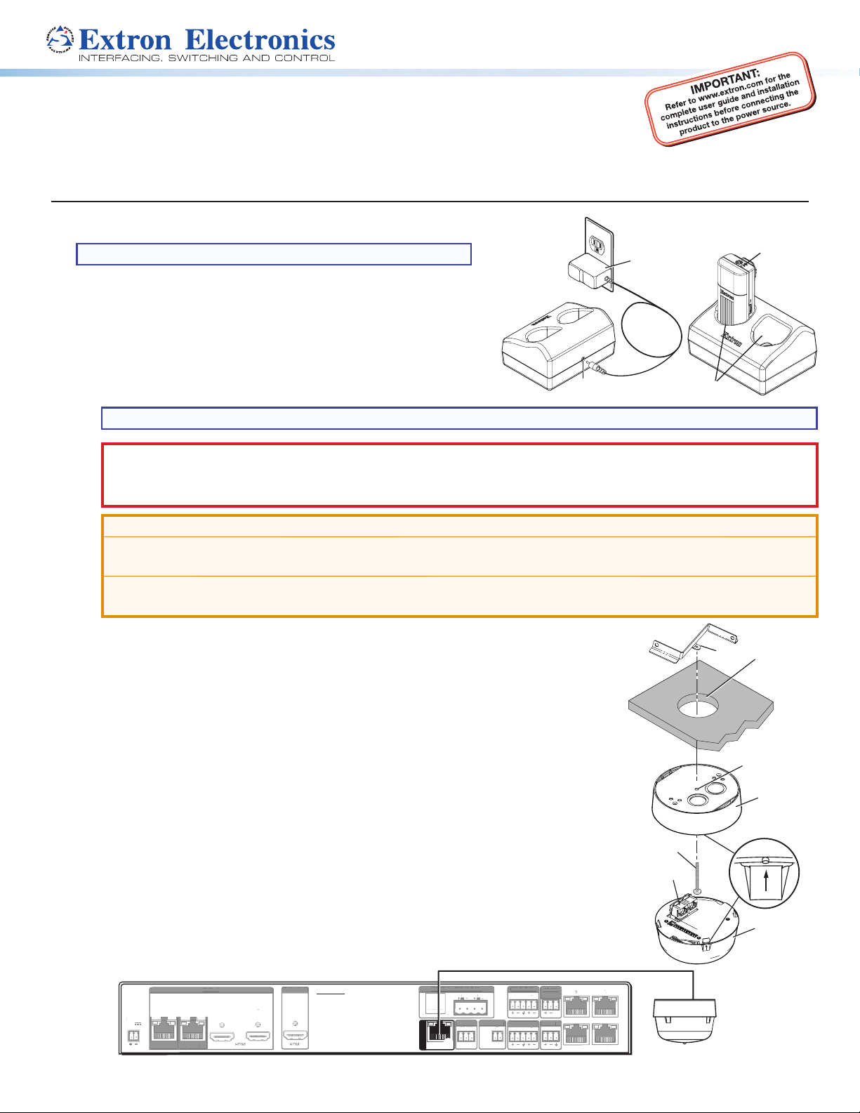
Installing the VLC 202 Charging Station
NOTE: For use with rechargeable NiMH batteries only.
To install the charging station (see the illustration at right):
1. Plug the wall charger (5 V, 1 A) into a wall outlet 1.
2. Connect the wall charger cable to the charging station power jack 2.
3. Install a battery in the microphone(s), following step 3 on the next
page. Ensure the microphone is turned off and place it in one of the
slots in the charger 3. The charge is complete when the microphone
LED turns green (this can take up to 5 hours).
NOTE: Microphones can be left to charge for extended periods. They should be turned off while charging.
CAUTION:
• Do not replace the battery with an incorrect type. Use only NiMh or alkaline batteries.
• Ne pas remplacer la pile par le mauvais type de pile. Utilisez seulement des piles de type NiMh ou alkaline.
ATTENTION:
• Do not charge alkaline batteries.
• Ne rechargez pas les piles alkalines.
• Be sure to replace the battery with the correct type and to dispose of used batteries appropriately.
• Assurez vous de remplacer les piles par le bon modèle et de jeter les piles usagées de façon appropriée.
1
23
LED
Installing the VLR 102 Receiver
To install the VLR 102 IR Receiver in a drop ceiling:
1. Remove a ceiling tile from the desired location and cut a hole 2 to 3 inches (5.0-7.6 cm)
in diameter 1.
2. Separate the receiver base plate Õand the dome Öby gripping the base plate and
turning the dome (counter clockwise, about an inch) until it comes free.
3. Align the center of the receiver base plate 3with the hole in the ceiling tile 1.
4. Insert the mounting screw 4through the base plate and the hole in the ceiling tile 1.
5. Attach the provided Z-bracket 5to the end of the screw 4on the rear side of the
ceiling tile. Replace the ceiling tile.
6. Pull a shielded CAT5 cable to the receiver location, and connect one end to the RJ-45
jack 6(labeled OUT) on the receiver dome Ö.
7. Align the arrow on the dome tab with the raised arrow on the edge of the base
plate 7. Rotate the dome clockwise until the arrow on the tab aligns with the
raised dot on the base plate (7inset).
8. Connect the other end of the shielded CAT5 cable from the receiver to the
VoiceLift RJ-45 connector 8of the PoleVault switcher (see image below).
3A MAX
POWER
12V
1/2
SIG LINKSIG LINK
3/4
INPUTS
PVT IN PVT IN
13
PVS 407D
4
T
REMOTE
RS-232
Tx Rx G
OVER PVT
IR
SG
AUDIO OUT PAGING
SENSOR
LR
+V
AUXINPUT 5
LR
OUTPUT
LR
DO NOT
GROUND
OR SHORT
SPEAKER
OUTPUTS
4/8
Ω
AMPLIFIED AUDIO OUT
CLASS 2 WIRING
2
56
UDI
UT
A
IN
EN
R
N
R
N
R SHORT
PEAKE
UTPUT
8
MPLIFIED AUDI
U
LA
2 WIRIN
EM
TE
-232
x
VER PV
5
OWE
1
2
I
NPUT
UTPUT
6
8
VLR 102
Out
PVS 407D PoleVault Switcher
1
5
3
Õ
Dome
4
6
Ö
Base Plate
7
1


