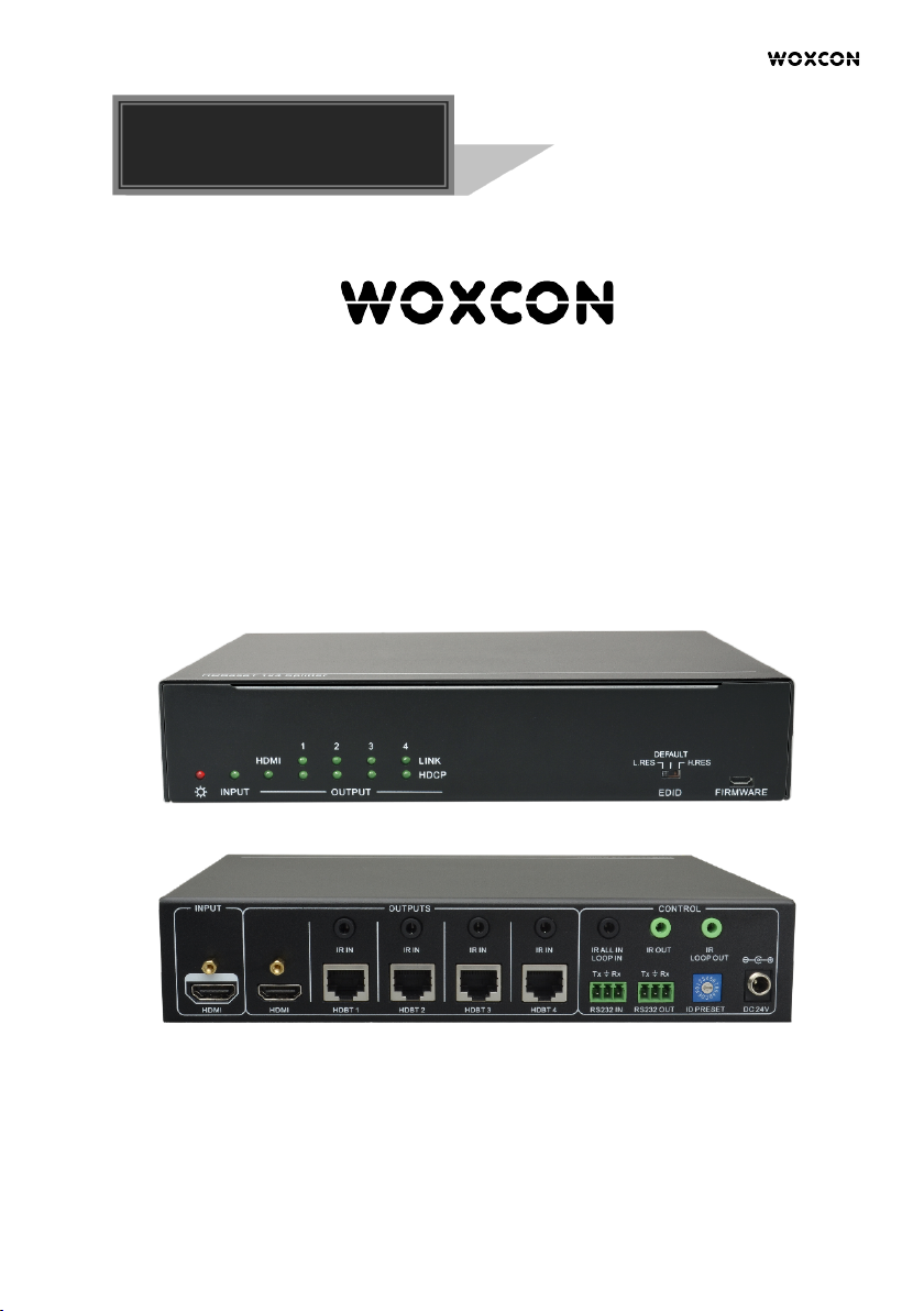
HDBaseT 1x4 Splitter Kit ( PoH )
4
Contents
1. Product Introduction .................................................................................................... 1
1.1 Features ............................................................................................................. 1
1.2 Package List ....................................................................................................... 2
2. Technical Specifi c a t i o n ................................................................................................ 3
2.1 HDBaseT Splitter ................................................................................................ 3
2.2 HDBaseT Receiver ............................................................................................. 4
3. Panel Description ........................................................................................................ 5
3.1 HDBaseT Splitter Front Panel ............................................................................ 5
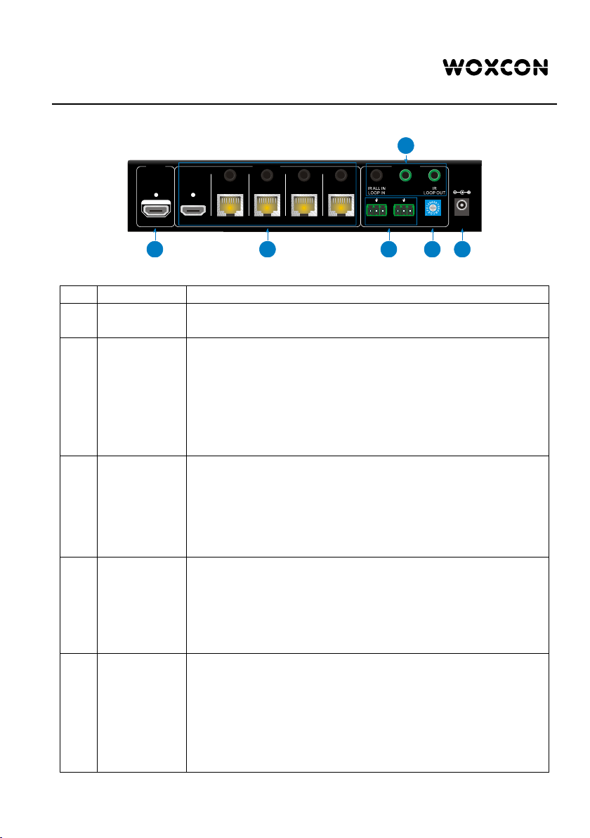
3.2 HDBaseT Splitter Rear Panel ............................................................................. 6
3.3 HDBaseT Receiver Front Panel ......................................................................... 7
3.4 HDBaseT Receiver Rear Panel .......................................................................... 8
4. System Connection ..................................................................................................... 9
4.1 Usage Precautions ............................................................................................. 9
4.2 System Diagram ................................................................................................. 9
4.3 Cascade Connection ........................................................................................ 10
5. IR Control ................................................................................................................... 11
5.1 Controlling the Display Device by IR IN ........................................................... 11
5.2 Controlling the Display Device by IR ALL IN .................................................... 12
5.3 Controlling the Source Device .......................................................................... 13
6. RS232 Control ........................................................................................................... 14
6.1 RS232 Control Software ................................................................................... 14
6.2 RS232 Command Format ................................................................................ 16
7. EDID Management .................................................................................................... 18
8. Panel Drawing ........................................................................................................... 19
9. Troubleshooting & Maintenance ................................................................................ 20
10. Customer Service .................................................................................................... 21