CYP CSC-5500 User manual

CSC-5500
Multiple Inputs to HDMI/VGA Scaler
Operation Manual
Operation Manual


DISCLAIMERS
The information in this manual has been carefully checked and
is believed to be accurate. Cypress Technology assumes no
responsibility for any infringements of patents or other rights of third
parties which may result from its use.
Cypress Technology assumes no responsibility for any inaccuracies
that may be contained in this document. Cypress also makes no
commitment to update or to keep current the information contained
in this document.
Cypress Technology reserves the right to make improvements to this
document and/or product at any time and without notice.
COPYRIGHT NOTICE
No part of this document may be reproduced, transmitted,
transcribed, stored in a retrieval system, or any of its part translated
into any language or computer le, in any form or by any means—
electronic, mechanical, magnetic, optical, chemical, manual, or
otherwise—without express written permission and consent from
Cypress Technology.
© Copyright 2011 by Cypress Technology.
All Rights Reserved.
Version 1.1 August 2011
TRADEMARK ACKNOWLEDGMENTS
All products or service names mentioned in this document may be
trademarks of the companies with which they are associated.

SAFETY PRECAUTIONS
Please read all instructions before attempting to unpack, install or
operate this equipment and before connecting the power supply.
Please keep the following in mind as you unpack and install this
equipment:
• Always follow basic safety precautions to reduce the risk of re,
electrical shock and injury to persons.
• To prevent re or shock hazard, do not expose the unit to rain,
moisture or install this product near water.
• Never spill liquid of any kind on or into this product.
• Never push an object of any kind into this product through any
openings or empty slots in the unit, as you may damage parts
inside the unit.
• Do not attach the power supply cabling to building surfaces.
• Use only the supplied power supply unit (PSU). Do not use the PSU
if it is damaged.
• Do not allow anything to rest on the power cabling or allow any
weight to be placed upon it or any person to walk on it.
• To protect the unit from overheating, do not block any vents or
openings in the unit housing that provide ventilation and allow for
sufcient space for air to circulate around the unit.
REVISION HISTORY
VERSION NO. DATE (DD/MM/YY) SUMMARY OF CHANGE
VR0 27/06/13 Preliminary Release
VS1 24/07/13 Updated format/diagrams
VR2 08/04/15 RS-232 Command
VS3 22/06/16 Corrected RS-232 CR+LF
command

CONTENTS
1. Introduction............................................ 1
2. Applications........................................... 1
3. Package Contents ................................ 1
4. System Requirements............................ 1
5. Features.................................................. 2
6. Operation Controls and Functions....... 3
6.1 Front Panel ........................................3
6.2 Rear Panel.........................................4
6.3 Remote Control................................5
6.4 OSD Menu.........................................6
6.5 IR Cable Pin Assignment................10
6.6 RS-232 Protocols .............................11
6.7 RS-232 and Telnet Commands .....11
6.8 Telnet Control .................................15
6.9 WebGUI Control .............................17
7. Connection Diagram .......................... 18
8. Specications ...................................... 19
8.1 Technical Specication.................19
8.2 Input Resolution..............................20
8.3 Output Resolution ..........................21
9. Acronyms ............................................. 22

1
1. INTRODUCTION
This Multi Input Scaler has Composite Video, Component Video, PC
(VGA), and HDMI inputs and can switch and scale the signal to HDMI
or VGA with audio outputs. It supports HDMI output resolutions up
to 1080p/WUXGA and Analog Digital Conversion (ADC) and Digital
Analog Conversion (DAC) allowing a wide range of AV signals to be
displayed on a HDMI or VGA display. Further, the On-screen Display
(OSD), IR remote, RS-232, IP and on-panel controls make this product
very versatile.
2. APPLICATIONS
• Analog and digital source integration
• Upscaling standard denition video for high-denition displays
• Conference centres
• Lecture halls
• Schools and universities
3. PACKAGE CONTENTS
• 1×Multiple Inputs to HDMI/VGA Scaler
• 1×15-pin D-Sub to 3 RCA Adaptor Cable
• 1×IR Extender Cable
• 1×Remote Control (CR-122)
• 1×5 V/3 A Power Adaptor
• 1×Operation Manual
4. SYSTEM REQUIREMENTS
Source equipment such as Blu-ray/DVD players or PC/Laptop and
output to displays, AV Receivers or active speakers.

2
5. FEATURES
• Supports switching and scaling of multiple AV inputs to HDMI or PC/
HD outputs
• Supports EDID and HDCP
• Supports 3D de-interlace, noise reduction and 3D comb lter
• Supports frame rate conversion
• Supports RS-232, IP (Telnet/WebGUI) and IR controls
• Supports output timing hot keys switching
• HDMI compatible with DVI
• Supports Digital to Analog (DAC) and Analog to Digital (ADC) Audio
conversion
• Supports non-HDCP signal of Apple computers

3
6. OPERATION CONTROLS AND FUNCTIONS
6.1 Front Panel
UNEM3IMDH2IMDH1IMDH3CP2CP1CPPMOCVCREWOP
XGA
ENTER
-
+
720P
3 4 5 621
1POWER & LED: Press this button to switch the device on or to set it to
standby mode. Once the device is connected to an active power
supply and the Power Switch on the back panel is turned on, the
LED will illuminate and the device will switch on automatically.
2IR Window: Receives only the IR signal from the remote control
included in the package.
3INPUT & LEDs: Press these buttons to switch directly to the required
source. An LED will illuminate to indicate the selected input source.
4MENU: Press this button to enter the On-screen Display (OSD)
menu.
5Plus/Minus (−/+): Press these buttons to navigate down and up in
the OSD menu.
6ENTER: Press this button to conrm the selection in the OSD menu.
Note: Press this button simultaneously with the '+' (plus) button to
instantly switch the output to XGA resolution or with the '−' (minus)
button to instantly switch the output to 720p resolution.

4
6.2 Rear Panel
POWER
DC 5V
CONTROL
HDMI 2HDMI 1 PC/HD
RS232 COAX AUDIO
SERVICE
OUTPUT
3CP2CP1CP3IMDH2IMDH1IMDH Cr/Pr Cb/Pb
RL
YRLCV
AUDIO
INPUT
IR IN
5 84
1 2 3 6 7
1IR IN: Connect the supplied IR extender to receive the IR signal
from the included IR remote. Ensure that the remote is within the
direct line-of-sight of the IR extender.
2SERVICE: Reserved for manufacturer use only.
3RS-232: Connect to a PC/Laptop or RS-232 control system to
use RS-232 commands to control the device (See Section 6.5 for
details).
4OUTPUT
(1) HDMI 1~2: Connect to an HDMI display or AV Receiver for video
and/or audio output.
(2) PC/HD: Connect to a monitor/display for video output. For
HD (Component) output, use the supplied D-Sub 9pin to 3 RCA
adaptor cable for HD resolutions from 480p~1080p.
Note: When the selected HDMI input source signal has HDCP
content the VGA/Component output will not display any image.
(3) COAX: Connect to an amplier or active speakers for audio
output in digital format.
Note: When the input audio source signal is in bitstream format
and the AUDIO SOURCE setting is set to AUTO in the OSD menu,
the coaxial output will bypass the input audio signal including
compatible surround sound formats.
(4) AUDIO: Connect to an amplier or active speakers for audio
output in stereo format.
5INPUT
(1) HDMI 1~3: Connect to HDMI sources such as Blu-ray/DVD player
for both video and audio signal conversion.
(2) PC 1~3: Connect to a PC/Laptop source for video signal input
with a 15-pin D-Sub cable.

5
(3) 3.5mm Mini-jacks: Connect to source's L/R output with 3.5mm
mini-jack for audio signal conversion.
Note: For HDMI signals you can select in the OSD Menu whether
you require audio from the HDMI (AUTO) or from the analog audio
inputs (EXT)
(4) YCbCr/YPbPr + L/R: Connect to source equipment such as a
DVD player for both video and audio signal conversion.
(5) CV + L/R: Connect to a composite video source such as a
video/DVD player for both video and audio signal conversion.
6CONTROL: This port is the link for Telnet or WebGUI controls,
connect to an active Ethernet link with an RJ45 terminated cable
7POWER: Switch this power toggle to turn on and activate the
device or turn off to shut it down.
8DC 5V: Connect the power adaptor included in the package to
the device and plug it into an AC wall outlet for power supply.
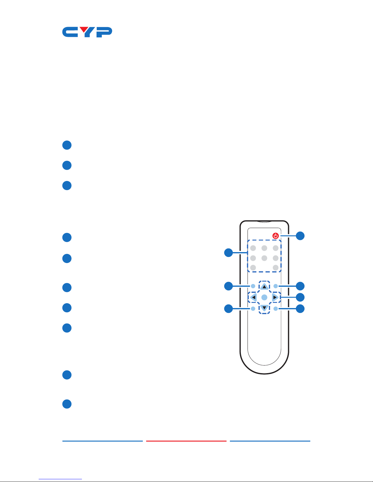
6.3 Remote Control
1POWER: Press this button to switch the
device on or to set it to standby mode.
2HDMI 1~3, PC 1~3, CV & COMP: Direct
source selection keys. Press one of these
keys to switch to the required source.
3MENU: Press this button to enter the OSD
menu.
4EXIT: Press this button to exit the menu or
the current selection in the OSD menu.
5 OK & ▲/▼/◄/►: Press OK to conrm the
selection or press the arrow buttons to
navigate the OSD menu. When the OSD
menu is not active, use the LEFT/RIGHT
(◄/►) to control the volume level.
6AUTO ADJUST: Press this button when the
image being outputted does not correctly t the display's screen.
The device will auto adjust the image to ll the screen.
7RESET: Press this button to reset the device back to the default
settings.
CR-122
POWER
EXIT MENU
OK
RESET AUTO
ADJUST
PC1PC2 PC3
CV COMP
HDMI2HDMI1 HDMI3
1
3
6
5
4
7
2

6
6.4 OSD Menu
MAIN MENU SUB MENU 3RD MENU 4TH MENU
DISPLAY OUTPUT 640×480 60
800×600 60
1024×768 60
1280×768 60
1360×768 60
1280×720 60
1280×800 60
1280×1024 60
1440×900 60
1400×1050 60
1680×1050 60
1600×1200 60
1920×1080 60
1920×1200 60
1280×720P 60*
1920×1080I 60
1920×1080P 60
720×576P 50
1280×720P 50
1920×1080I 50
1920×1080P 50

7
MAIN MENU SUB MENU 3RD MENU 4TH MENU
DISPLAY SIZE OVER SCAN
FULL*
FOLLOW INPUT
PAN SCAN
LETTER BOX
UNDER 2
UNDER 1
MODE INFO OFF
INFO*
ON
INPUT HDCP
(HDMI source
only)
OFF
ON*
PC (PC source
only)
AUTO SETUP
H_POSITION
V_POSITION
PHASE
CLOCK
WXGA/XGA XGA*
WXGA
RESET
TIMING SHIFT OFF*
ON

8
MAIN MENU SUB MENU 3RD MENU 4TH MENU
COLOR CONTRAST 0~60 (30)
BRIGHTNESS 0~60 (30)
COLOR R 0~1023 (512)
G 0~1023 (512)
B 0~1023 (512)
R OFFSET
0~1023 (512)
G OFFSET
0~1023 (512)
B OFFSET
0~1023 (512)
HUE 0~60 (30)
SATURATION 0~60 (30)
SHARPNESS 0~30 (0)
NR. OFF*
LOW
MIDDLE
HIGH
AUDIO VOLUME 0~100 (100)
DELAY OFF*
40ms
110ms
150ms
SOUND ON*
MUTE
SOURCE
(HDMI mode
only)*1
AUTO*
EXT.

9
MAIN MENU SUB MENU 3RD MENU 4TH MENU
SETUP FACTORY
RESET*2
KEY LOCK OFF*
ON
POWER SAVE OFF*
ON
IP MODE DHCP*
STATIC
SET STATIC IP IP ADDRESS 0.0.0.0.~
255.255.255.255*3
SUBNET MASK 0.0.0.0.~
255.255.255.255*4
DEF.GETWAY 0.0.0.0.~
255.255.255.255*5
FREERUN
COLOR
BLACK
BLUE*
INFORMATION INPUT
OUTPUT
REVISION
IP ADDRESS
Note:
1. When AUDIO SOURCE sets to 'AUTO', if the selected HDMI
input port is connected to an HDMI source, audio signal of the
source will be used for output; if the selected HDMI input port is
connected to a DVI source, audio signal from the 3.5mm phone-
jack on top of the selected HDMI input port will be used. When
AUDIO SOURCE sets to 'EXT',only the audio signal from the 3.5mm
phone-jack on top of the selected HDMI input port will be used for
output.

10
2. The FACTORY RESET option in the OSD menu will only reset part of
settings. For a complete reset of the system, please use the reset
button on the remote control.
3. 192.168.0.1 (Default setting).
4. 255.255.255.0 (Default setting).
5. 192.168.0.254 (Default setting).
6. Items in BOLD with an asterisk (*) are the Factory default settings.
Items in brackets are the default values for those settings.
6.5 IR Cable Pin Assignment
3
1
2
3
2
1
IR Signal
Power
Grounding
IR Extender

11
6.6 RS-232 Protocols
SCALER
►
◄
REMOTE CONTROL
Pin Assignment Pin Assignment
1 NC 1 NC
2Tx 2Rx
3Rx 3Tx
4 NC 4 NC
5 GND 5 GND
6 NC 6 NC
7 NC 7 NC
8 NC 8 NC
9 NC 9 NC
Baud Rate: 19200bps
Data bit: 8 bits
Parity: None
Flow Control: None
Stop Bit: 1
6.7 RS-232 and Telnet Commands
COMMAND DESCRIPTION
S POWER 0/1 0=OFF 1=ON
R POWER Reports the numeric equivalent for POWER
setting (as above)
S SOURCE 1~8 1=HDMI 1
2=HDMI 2
3=HDMI 3
4=YPbPr
5=VIDEO
6=PC 1
7=PC 2
8=PC 3
R SOURCE Reports the numerical equivalent for
SOURCE setting (as above)

12
COMMAND DESCRIPTION
S OUTPUT 0~21*10=640×480
1=800×600
2=1024×768
3=1280×768
4=1360×768
5=1280×720
6=1280×800
7=1280×1024
8=1440×900
9=1400×1050
10=1680×1050
11=1600×1200
12=920×1080
13=1920×1200
14=480p
15=720p6@0
16=1080i@60
17=1080p@60
18=576p
19=720p@50
20=1080i@50
21=1080p@50
R OUTPUT Reports the numerical equivalent for
OUTPUT setting (as above)
S SIZE 0~6 0=OVERSCAN
1=FULL
2=FOLLOW INPUT
3=PAN SCAN
4=LETTER BOX
5=UNDER 2
6=UNDER 1
R SIZE Reports the numerical equivalent for SIZE
setting (as above)
S INPUT HDCP 0/1 0=ON 1=OFF
R INPUT HDCP Apple Computers Only. Reports the
numerical equivalent for INPUT HDCP
setting (as above)
S SYNCSHIFT 0/1 0=ON 1=OFF
R SYNCSHIFT Reports the numerical equivalent for
SYNCSHIFT setting (as above)
S CONTRAST 0~60 Sets the numerical equivalent for CONTRAST
setting (0~60)
R CONTRAST Reports the numerical equivalent for
CONTRAST setting
S BRIGHTNESS 0~60 Sets the numerical equivalent for the
BRIGHTNESS setting (0~60)

13
COMMAND DESCRIPTION
R BRIGHTNESS Reports the numerical equivalent for the
BRIGHTNESS setting
S HUE 0~60 Sets the numerical equivalent for the HUE
setting (0~60)
R HUE Reports the numerical equivalent for the
HUE setting
S SATURATION 0~60 Sets the numerical equivalent for the
SATURATION setting (0~60)
R SATURATION Reports the numerical equivalent for the
SATURATION setting
S SHARPNESS 0~30 Sets the numerical equivalent for the
SHARPNESS setting (0~60)
R SHARPNESS Reports the numerical equivalent for
SHARPNESS setting
S NR 0~3 0=OFF
1=LOW
2=MIDDLE
3=HIGH
R NR Reports the numerical equivalent for the
NOISE REDUCTION setting (as above)
S VOLUME 0~100 Sets the numerical equivalent for VOLUME
setting (0~100)
R VOLUME Reports the numerical equivalent for
VOLUME setting
S AUDIO DELAY 0~3 0=OFF
1=40ms
2=110ms
3=150ms
R AUDIO DELAY Reports the numeric equivalent for the
AUDIO DELAY setting (as above)
S AUDIO MUTE 0/1 0=ON 1=MUTE
R AUDIO MUTE Reports the numeric equivalent for the
AUDIO MUTE setting (as above)
S HDMI AUDIO 0/1 0=AUTO 1=EXT
R HDMI AUDIO Reports the numeric equivalent for HDMI
AUDIO setting (as above)
S KEY LOCK 0/1 0=ENABLE 1=DISABLE

14
COMMAND DESCRIPTION
R KEY LOCK Reports the numeric equivalent for KEY
LOCK setting (as above)
S FREERUNCOLOR 0/1 0=BLACK 1=BLUE
R FREERUNCOLOR Reports the numerical equivalent for the
free run color setting (as above)
S RESET 1 Sets the numerical equivalent for RESET
setting (as left)
PORT 0~8 0=LAST MEMORY
1=HDMI 1
2=HDMI 2
3=HDMI 3
4=YPbPr
5=VIDEO
6=PC 1
7=PC 2
8=PC 3
ST Checks the FIRMWARE version and SOURCE
information:
0.00~x.xx
SOURCE: HDMI ~ PC3
PORT ON: LAST ~ PC3
VOL + Raises the volume level (VOLUME * IS SET)
VOL - Lowers the volume level (VOLUME * IS SET)
QUIT Exit. (Telnet Only)
Note:
1. Resolution settings 0~13 are RGB encoded. Resolution settings
14~21 are YUV encoded.
2. RS-232 commands will be not executed unless followed with a
carriage return (CR) command and a Line feed (LF) command.
Commands are case-insensitive.

15
6.8 Telnet Control
Before attempting to use the Telnet control, ensure that both the
Scaler (via the LAN port) and the PC/Laptop or control system being
used are connected to the same active network.
To access the Telnet control in Windows 7, click on the 'Start' menu
and type 'cmd' into the Search eld then press Enter (see below for
reference). Under Windows XP, go to the 'Start' menu and click on
'Run', type 'cmd' then press Enter.
Under Mac OS X, go to the le menu then navigate to
GoApplicationsUtilitiesTerminal (see below for reference).
Once in the command line interface (CLI) type 'telnet' along with the
IP address of the unit you wish to control (see below for reference).
This will bring us into the device which we wish to control.
Note: The IP address can be obtained from the OSD menu under
Information. If the IP is changed then the IP Address required for Telnet
access will also needs to be change accordingly.
Other manuals for CSC-5500
2
Table of contents
Other CYP Media Converter manuals