Ferrofish A32pro User manual

2
Manual
A32pro
A32pro Dante
32x32 Channel A/D-D/A Converter & Router

2
Dear users,
We are very pleased that you have chosen the A32pro series as your new converter.
With this device, we want to offer you a real added value in your daily tasks. During the
development, we have followed the approach of the highest possible compatibility in both
design and selection of interfaces in order to be able to cover as many scenarios as
possible in practice. Hopefully you will have as much fun using the device as we had
developing it.
Introduction
JÜRGEN KINDERMANN
CEO & CTO FERROFISH GmbH
"With the A32pro series, FERROFISH is
responding to the constant evolution
in technological change with a new
modular platform. The new
possibilities for future expansions are
truly breathtaking."
KLAUS HASE
CEO & CFO FERROFISH GmbH
"The development of the A32pro
series took place in turbulent times.
We are even more proud of the new
A32pro series because it has already
exceeded our own high expectations.“
RUPERT
High Frequency Expert
"I was totally blown away by the
resolution of the high frequency range
and the precise stereo image of the
new A32pro series. This is the result of
the latest generation of ESS converters
and the circuitry that significantly
reduces jitter.“
About Ferrofish:!
Located in Linz on the Rhine, a team of developers, inventors, engineers and musicians has dedicated itself to
building exceptional audio devices with real added value. As a starting project, the successful A16 converter was
developed as the new A16 MKII version and became the bestseller in its class within a very short time. The success
continued with the A32, Verto and Pulse16 series of converters until today.
A32pro Series Manual: Introduction

3
Safety instructions
ATTENTION:
his device can produce volume levels high enough to cause hearing damage. Please apply caution and common sense when working with
loud audio signals. Avoid operating this device at uncomfortably loud volume levels for extended periods.Always take precautions to protect
the hearing of yourself and others. If you notice any signs of loss or damage to your hearing, seek appropriate medical attention.
WARNING!
To avoid the risk of electric shock, do not expose the unit, the power supply unit or the power cable to rain or moisture.
Only use the power supply unit on mains sockets with a protective earth connection (PE).
Never bypass or remove safety devices such as the protective earth conductor on the power supply unit or the appliance.
Do not operate the unit or the power supply near water or in environments with condensing humidity.
Do not place liquid containers on the unit.
Avoid direct contact with liquids. Avoid spraying or splashing the unit or the power supply unit with liquids of any kind.
This may damage the unit. Use only a dry cloth for cleaning. The appliance is maintenance-free.
Never cover or block the ventilation openings of the appliance. This could cause the unit to overheat.
Disconnect the appliance from the mains if it is not going to be used for a long time or during a thunderstorm.
Only use the unit within its intended voltage range. This is printed on the power supply unit. If you are not sure which mains
voltage prevails in your area of application, contact your local power supply company.
If the plug of the power supply unit supplied does not fit into the mains socket, contact an electrician.
Only use power supply units, spare parts and other accessories approved by the manufacturer.
Other mains adapters may cause the unit to malfunction or even become defective.
Observe the maximum electrical load capacity of your operating environment. Do not exceed this load limit, as overloading can lead to fires.
Do not make any modifications - electrical or otherwise to the unit or power supply unit. Doing so will void the warranty
and the unit will lose its CE approval.
Do not insert any objects or foreign objects through the ventilation openings of the unit.
This could lead to a short circuit inside the unit and a defect.
Operate the unit only in safe positions. Prevent the unit from falling, which can cause injury to persons or damage to the unit.
When mounting the unit in a rack, use all four mounting holes to ensure a tight fit.
All service work and repairs must only be carried out by a customer service authorized by the manufacturer.
Service work is necessary as soon as the unit or its power supply unit has been damaged in any way, such as:
• Damage to the power supply unit or power cord.
• Liquids/object has entered the unit.
• The unit has been exposed to rain or moisture.
• If it is not working normally or has been dropped.
If your device has sustained damage, contact your dealer and/or the manufacturer to arrange a repair.
A32pro Series Manual: Safety instructions
Safety instructions:
Please read and follow all instructions contained within this manual,
and carefully observe all warnings and safety instructions.
This manual should be stored in a safe place for future reference.
4
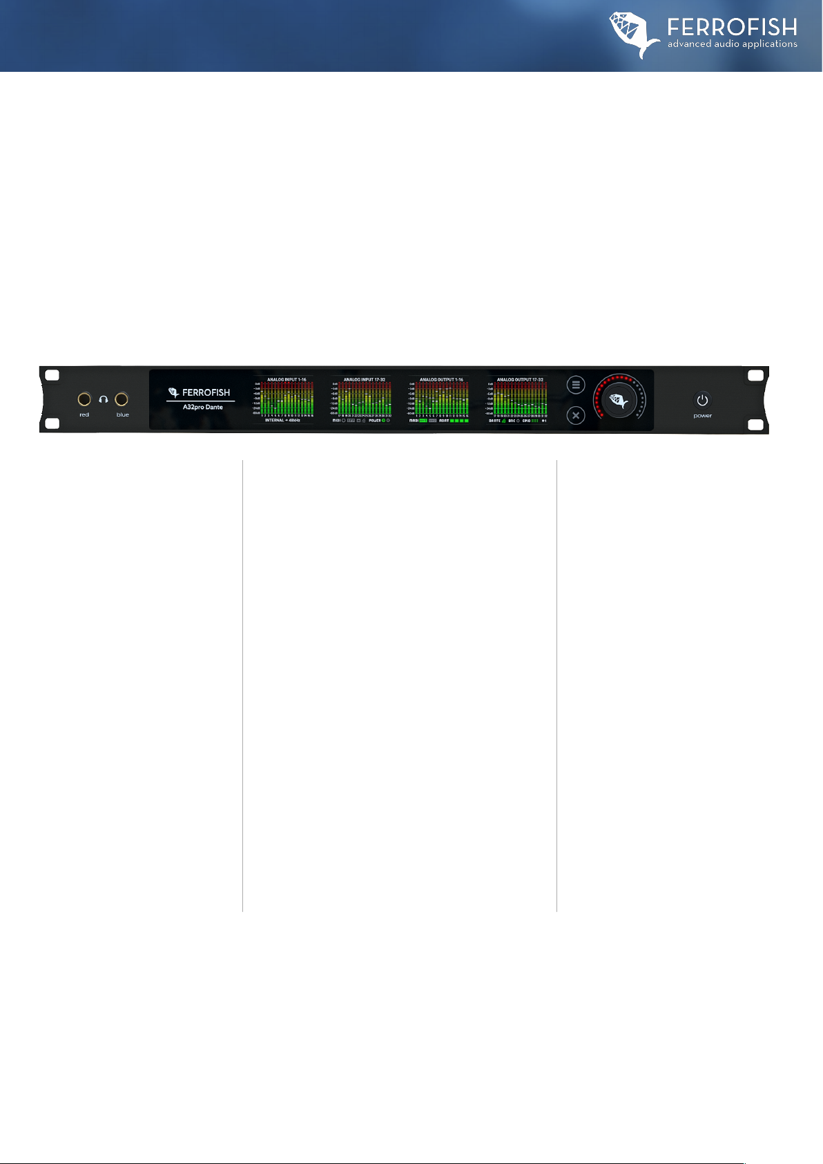
Welcome to the A32pro series. In this manual we would first like to welcome you with a virtual
tour. Let's start with a description of the individual front sections of an A32pro Dante, beginning
from the left. The front panels of the A32pro and A32pro Dante are identical in function:
Front View
A32pro Series Manual: Front View
Headphones outputs
The two independent headphones
outputs are driven by high-quality
amplifier components from Texas
Instruments. Depending on the
configuration, these can either
function as two independent stereo
outputs („unbalanced“) or operate in
balanced mode for use with high-end
headphones. For balanced operation,
each output is responsible for one
driver side of the headphones.
For balanced operation, you need a
balanced cable for the headphones -
of course, the headphones must also
support balanced operation due to
their design. To access the headphone
menu or the monitoring matrix, tap
the encoder wheel in the main menu
(analog I/O display). You will learn
more about the headphone menu in
the next chapters.
Section with device name, TFT screens
The area with the unit name and the company logo is
touch-sensitive and intended for special functions,
such as clearing the peak LEDs.
The four color screens, which are also touch-sensitive,
show both the status of the 32 analog inputs and outputs
and the status of the unit.
The status bar in the lower area represents the
following, starting from the left:
∙Synchronisation source and sample frequency
∙MIDI activity on the MIDI sockets, SFP module(s),
USB and Dante*.
∙Status of power supply at inputs 1 & 2 Sync status of:
MADI SFP ports, ADAT ports, Dante interface* and BNC.
∙Activity of the GPIO ports: The top row shows the four
inputs, the bottom row the four outputs.
∙Number of the currently loaded preset
(* A32 Dante only)
Operating elements
The operating elements consist of the
following elements:
∙Menu (three bars/„hamburger key")
∙Back/Escape („X“ symbol)
∙Encoder knob (touch sensitive)
∙Power switch.
Please note that the touch keys and
the touch sensitivity of the encoder
are capacitive.
Operation with gloves may possibly
impair the touch functionality of the
screens.
5
ATTENTION: The unit produces heat. Leave at least 1RU free above
and below the unit to ensure sufficient ventilation.
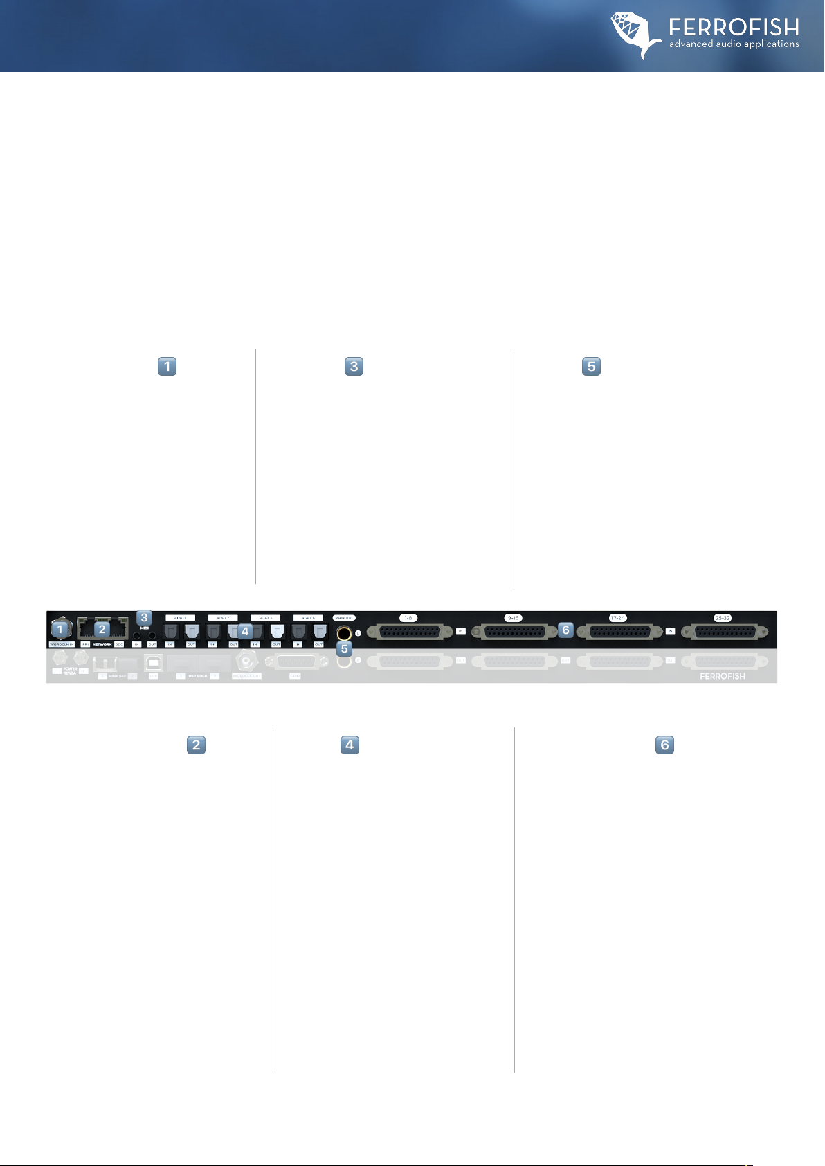
Back View I
A32pro Series Manual: Back View I
The connections on an A32pro Dante are explained below. Differences to the A32pro are indicated with an asterisk. (* A32pro Dante only)
MIDI IN/OUT !
The MIDI inputs and outputs are provided in
1/8“ (3.5mm) jack sockets. Adapters to 5-pin
DIN plugs are available in stores or from the
FERROFISH online-webshop.The pinout
corresponds to the MIDI 2.0 (Type A)
specification. This can be used to remotely
control the unit or to update the firmware.
Remote control is either possible via the
RemoteFish app or MIDI CC Control Mode.
NETWORK Pri/Sec Dante* "
The Dante interface allows seamless
integration into existing Dante audio
networks, which are based on normal
network data traffic (Layer3).
At higher sample rates, Dante also
reduces the number of channels to be
transmitted to 32x32 channels at double
sample rates (SMUX/2, up to 96k) and to
16x16 at quadruple sample rates
(SMUX/4, up to 192k). Furthermore, the
Dante interface offers redundancy
connectivity to increase transmission
security. For more details, please visit:
www.audinate.com.
WORDCLOCK INPUT #
The wordclock input is responsible for
receiving a clock from other digital
devices, when"BNC" is selected in the
clock source menu. The A32pro Dante
can then be used in a network of several
digital devices, as a wordclock slave/
follower from an external wordclock
signal.
ADAT I/O $
The A32pro series has four ADAT input
and output pairs of optical TOSLINK
ports to transport all 32x32 channels
at single sample rates (SMUX/1, up to
48kHz). The maximum cable length is
5m. When transmitting sample rates
higher than 48kHz, the number of
available channels is reduced by half
(16x16) up to 96k and by half again
(8x8) up to 192k.
The sockets with the bright-colored
flap are the ADAT outputs,
the sockets with the black flap are the
ADAT inputs.
MAIN OUT %
A MAIN OUT connection in the form of two
balanced 6.3mm (1/4“) jacks is provided for the
quick connection of devices such as studio
monitors or analog stereo recording devices.The
main out mirrors the signal of the red
headphone output. The volume is thus
controlled via the headphone menu.
The MAIN OUT accepts balanced and
unbalanced devices.
ANALOG INPUTS (1-32) &
Due to the compact housing, the
analog inputs are in dSub25 (or db25)
format. The pin assignment
corresponds to the Tascam format.
The maximum input level is +20dBu.
All inputs are fully balanced.
Fitting breakout cables are available
in stores or from the FERROFISH
webshop.
#
"
!
$
%
&

6
Back View II
A32pro Series Manual: Back View II
The connections on an A32pro Dante are explained below. Differences to the A32pro are indicated with an asterisk. (* A32pro Dante only)
USB - A PORT !
The USB port is used to control the
A32pro Dante via MIDI-over-USB
and to update the firmware.
When connected to a PC or Mac, a
class-compliant USB MIDI interface is
installed without any extra drivers.
This virtual MIDI port can be used to
remotely control the unit via the
Remote Fish app (available for PC and
Mac) or via MIDI CC mode.
Please note there is no audio
transmission via USB.
Dual POWER Input (1/2) #
The dual sockets of the power supply
inputs enable redundant operation
with two power supplies, which
reduces the probability of the unit
failing due to power supply failure.
The A32pro series ship with one PSU
as standard. Additional power
supplies can be purchased from the
manufacturer or from dealers. Both
inputs can be permanently monitored.
If the voltage at one input fails, this
can trigger an alert.
DSP STICK SLOTS $
The expansion ports are intended for later propietary
expansion modules. For more information, please
visit us at: www.ferrofish.com
WORDCLOCK OUT %
The BNC jack for the wordclock output is active as soon as
the device has been locked to a digital signal.This allows
other digital devices that are set to clock slave/follower to
be clocked by the A32pro (Dante).
DUAL MADI SFP SLOTS "
MADI SFP modules are plugged into
the SFP slots and can be exchanged
by the user at any time. Optical MADI
SFP modules in multi-mode and
single- mode configuration are
supported. Additional SFP modules
such as coaxial MADI I/O will be
available as an option. Also with
MADI, at higher sample rates the
original number of digital channels is
reduced from 64x64 (SMUX/1, up to
48kHz) to 32x32 (SMUX/2 up to
96kHz and again to 16x16 with
SMUX/4 (up to 192kHz). The use of
two SFP modules for 32x32 channels
at 192k is possible.
We recommend the use of original
FERROFISH SFP modules.
ANALOG Outputs (1-32) '
Due to the compact housing,
the analog outputs are in
dSub25 format. The pin
assignment corresponds to the
Tascam format. The maximum
input level is +20dBu.
All inputs are fully balanced.
Fitting breakout cables are
available in stores or from the
FERROFISH webshop.
GPIO PORT &
The GPIO (General Purpose
Input / Output) socket can be used
to select any of the first four presets
via the inputs. Alert messages can
be queried and monitored
externally via the outputs.
For the specifications of the I/O
ports, please refer to the technical
data in the appendix.
General Purpose Inputs:
GP Input 1-4: Load Preset#1-4 To
trigger a GP input, set the
corresponding pin to ground.
General Purpose Outputs:
GP Output1: "No Lock" Alert
This alert is triggered when the
A32pro can no longer lock to the
applied digital signal selected in the
Clock Source Menu.
GP Output2: Power Supply 1/2 Alert
This alert is triggered when one of
the two power supply inputs has
measured a voltage outside the
specifications.
GP Output3: MADI A/B Alert
This alert is triggered when the
signal fails at one of the two MADI
SFP modules.
GP Output4: Temperature Alert
This alert is triggered when the
temperature selected in the ALERT
menu (60 or 70°C) has been
reached or exceeded.
In the event of this alert, please
immediately ensure sufficient
cooling of the device to guarantee
continued trouble-free operation.
#
"
!
$
%
&
'
7
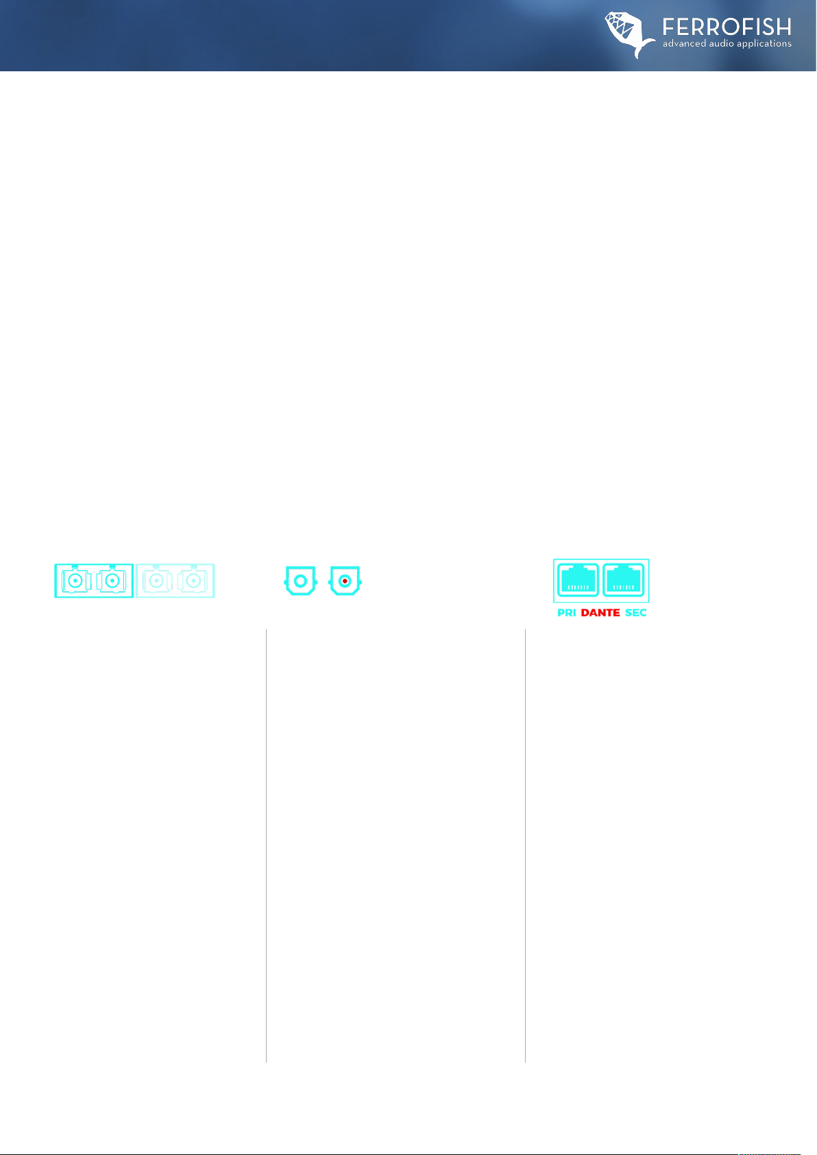
All digital interfaces of the A32pro series can be operated in sample rates up to 192kHz.
The number of channels that can be used depends on the sample rate used.
Digital Interfaces
A32pro Series Manual: Digital Interfaces
MADI I/O (64x64@24Bit/48k)
In its original format, the MADI protocol
could transmit 56x56 channels in 24Bit
and a maximum of 48kHz with the
possibility of adjusting the speed by +/-
12.5% (Varispeed).This format was
called "short frame" or
called AES10-1991. Later, the protocol
was extended by a "full frame" mode,
which had no Varispeed and was able to
transmit 64x64 channels. The usual
limitations on the number of channels
at higher sample rates apply:
SMUX/1 (up to 48k): 64x64 channels
SMUX/2 (up to 96k): 32x32 channels
SMUX/4 (up to 192k): 16x16 channels
The two SFP slots for the MADI modules
work as specified in the MADI menu. If
the priority is set, it is determined from
which module to switch to the other in
case of signal failure.
ADAT I/O (32x32@24Bit/48k)
The ADAT format is able to transmit a
maximum of 8 channels at 24 bits at up
to 48 kHz. For this purpose, plastic fibre
optic cables with TOSLINK plugs and
sockets are used for transmission. The
maximum cable length is between 3 and
5m, depending on the quality of the
cable. The units of the A32pro series are
equipped with 4 pairs of optical I/O ADAT
sockets to transmit all 32x32 channels at
single sample rates (SMUX/1).
At higher sample rates, the number of
available channels is as follows:
SMUX/1 (up to 48k): 32x32 channels
SMUX/2 (up to 96k):16x16 channels
SMUX/4 (up to192k): 8x8 channels
We recommend using MADI or DANTE*
for SMUX/4 operation due to the higher
number of channels.
DANTE I/O* (64x64@32Bit/48k)
The A32pro Dante is equipped with a
Dante Brooklyn board from Audinate.
With higher sample rates, the number of
channels to be transmitted is also
reduced with Dante. Thus, at double
sample rates (SMUX/2: 88.2 and 96kHz),
32x32 channels are still transmitted and
at quad sample rates (SMUX/4: 176.4
and 192kHz), 16x16 channels are still
transmitted. Only with the Dante format
it is possible to send and receive audio
streams with 32 Bits. Furthermore,
thanks to the two network sockets, the
Dante interface offers redundancy
connectivity, which automatically and
inaudibly switches to the other network
in the event of a failure of one Dante
network (regardless of whether PRI or
SEC). This switchover is automatic.
The configuration of the Dante board is
done via the "Dante Controller" app
from Audinate.
Single sample rates are transmitted by all digital interfaces of the devices of the A32pro series without limitation of the
number of channels. This range refers to sample rates up to 48kHz and is also called SMUX/1 or "Single Speed", as here the
data is transmitted via the audio channels in a simple configuration. SMUX/2 operation (also called "Double Speed")
describes the sample rate range up to 96kHz. Here, the number of channels is halved for all digital interfaces of the A32pro
series, since (mostly for reasons of limited bandwidth) two channels are used to transmit the channel in 96kHz. The
method used to bundle several channels to transmit an audio channel at higher sample rates is called "Signal
Multiplexing" (SMUX for short). SMUX/4 operation (also called "Quad Speed") describes the range up to 192kHz. Here, the
number of channels is halved again in relation to SMUX/2 (up to 96kHz) operation, since four channels must be combined
to transmit one channel at 192kHz.

8
Headphones - Monitoring Matrix & Main Menu
Operation
A32pro Series Manual: Operation
HEADPHONE MONITORING MATRIX
A monitoring matrix is integrated into the Headphones Menu, which allows you to monitor any input or output channel (except MAIN OUT)
of the device. This menu can be accessed by touching the encoder when you are in the main view of the unit, which displays the
32x32 analog inputs and outputs.
In general, the two headphone outputs can be operated in "unbalanced" (dual stereo) or "balanced" mode. You can switch between the modes
in the Headphone Setup Menu. The screen above shows the "unbalanced" mode, which will probably be the most common mode.
The screens show the two headphone outputs in the color assignment of red for the left output and blue for the right output.
You can change the volume in two ways: Either by tapping one of the two virtual rotary controls and setting the desired volume value on the
encoder or by tapping, holding and moving your finger on the virtual rotary control.This also works on the other touch buttons.
If the volume control is set to the lowest level (left stop), the message "off" appears in the display.
When the volume control is set to the highest level (right stop), the message "full" appears in the display.
Pressing the headphone symbol in the upper left or right corner will mute the corresponding channel.
Please note that you can select the overall amplification factor for the headphone outputs in the Headphone Setup Menu.
On the outer screens, make the following settings:
∙Type of interface of the channel to be monitored: analog, MADI (1/2),ADAT or DANTE*.
∙Input or output of the source to be monitored.
∙Channel format of the source to be monitored: mono, stereo, M/S (requires an M/S encoded signal)
∙Channel number of the source to be monitored
For MADI sources, select MADI 1 to monitor signals from the first SFP slot, or MADI 2 for the second SFP slot.

9
Operation - Main Menu
A32pro Series Manual: Main Menu
In the lower field of the respective button, the measured sample frequency is displayed. The current frequency of the wordclock generator of the
A32pro (Dante) is displayed in the "INTERNAL" field. If there is no readable frequency, "- - -" appears below the field.
To the left of the displayed sample frequency, a colored dot indicates the sync status of the applied signal:
•Grey: no signal has been detected.
•Yellow: a signal has been detected but cannot be synchronized to
•Green: synchronization was performed on this signal
INTERNAL
If you set the clock source to INTERNAL, the internal clock generator of the A32pro Dante is used.
MADI, ADAT
With MADI or ADAT, the wordclock is extracted from the respective data stream and processed with the help of the digital PLL.
The MADI and ADAT data stream also works at higher frequencies, where the number of available channels may be reduced. !
The buttons for MADI and ADAT show the measured wordclock frequency in the lower field, which can be helpful when troubleshooting
different digital devices.The number to the right of the sample rate display indicates which port is considered the preferred sync source by the
device. Since neither format has native recognition of SMUX/2 and SMUX/4, the measured sample rate in the SMUX/1 standard and its possible
multiples are displayed for selection.
BNC
An external wordclock can be connected directly to the device at the BNC-IN wordclock input.This is also processed by the jitter reduction circuit
before use.
DANTE
The wordclock of the DANTE device is displayed and used here. Note that if "Dante" is selected as the wordclock source, the wordclock of the
internal Brooklyn board or the "Preferred Master/Leader" on the Dante network will be used.
CLOCK
The CLOCK menu allows you to select the clock source and
sample frequency. The left screen is used to select the respective
source, the right screen enables you to select the frequency of
the wordclock in INTERNAL mode.
In all other modes except INTERNAL mode, the right screen
shows the measured wordclock frequency.
MAIN MENU
In the Main Menu you have access to the following fuctions:
∙CLOCK: Setting the wordclock source and sample rate.
∙HEADPHONE SETUP: Operating mode of the headphones output and maximum output level.
∙PRESET: Load, save and rename a total of eight presets.
∙SETUP: Further settings in separate sub menus (see next pages).
∙GAINS: Determines the maximum input level for analog inputs.
∙LEVELS : Determines the maximum output level for analog outputs.
∙ROUTING: Access to the routing matrix to connect inputs and outputs.

10
HEADPHONES SETUP
In this setup menu, you can set the amplification levels of
the two headphone outputs separately.These can be adjusted
to limit the maximum volume of an headphone output or
increased for higher impedance headphones.
In addition, the operating mode can be switched between
"unbalanced" (dual stereo) and „balanced".
The most common mode of operation for the two stereo outputs is probably "dual stereo", while "balanced" is intended for high-end headphones
with balanced cabling. In this case, the red output is used for the left driver of the headphones and the blue output for the right.
For the "balanced" mode, however, a special headphone cable is required from the headphone manufacturer. For safety reasons,
large volume jumps are prevented when selecting the gain levels.This is to protect your ears.
A32pro Series Manual: Main Menu
PRESET
In the preset menu, you can either load (LOAD), save (SAVE)
or rename (RENAME) one of eight presets.
Each preset can be assigned a name.
Naming and renaming of the preset names takes place
via an on-screen keyboard.
GAINS
The GAINS screen is used to adjust the sensitivity of the analog inputs. These are individually adjustable in 1dB steps from -8dBu to +20dBu.
The number below the fader indicates the maximum level that the converter can process. If the fader is set to a value of -7 on channel 1,
as in the picture above, the input can process a level of maximum -7dBu and would in this case output 0dBFS on the digital side. Values
exceeding this limit would lead to digital clipping.The meters are post-fader. In addition, you can see the level displays of the analog inputs so
that you can conveniently set the level correctly. You will find the dB scaling of the display on the right side of the screens. With a swipe gesture
at the points above and below the fader, you can select several channels and then adjust their value together with the encoder wheel.
The value of -8dBu corresponds approximately to the level of -10dBV for consumer devices such as CD players or a tape deck.
SETUP MENU
In the setup menu you have access to further adjustments
and functions, which, among other things, concern the
MADI and MIDI ports.
We will explain these in detail on the following pages.
SETUP MENU A32pro Dante
SETUP MENU A32pro
11
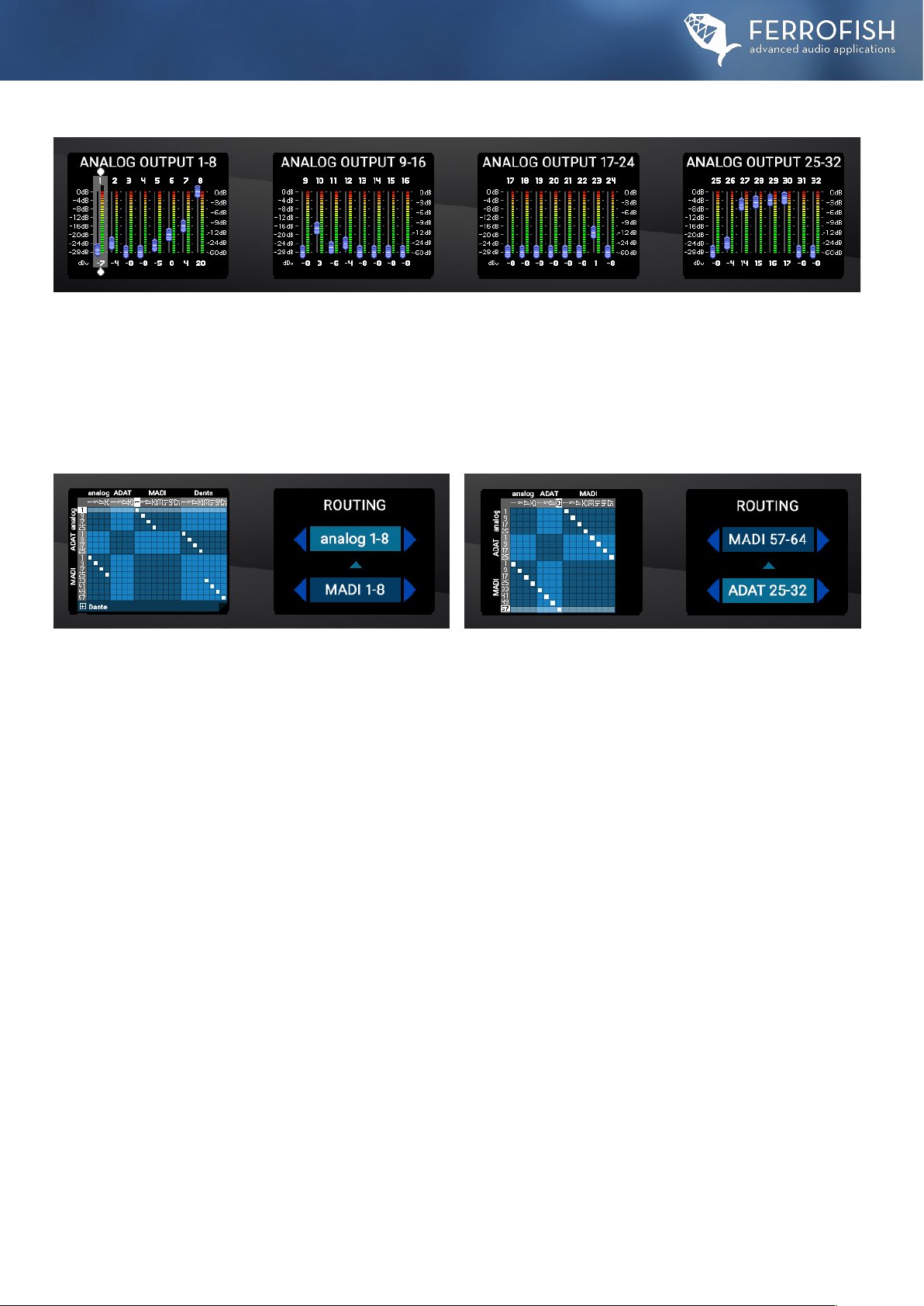
LEVELS
The LEVELS screen is similar to the GAINS screen, and determines the maximum levels of the analog outputs. Just like the inputs (GAINS),
the outputs are individually adjustable in 1dB steps from -8dBu to +20dBu. Here, too, there is the level display of the outputs.
Please note that here the level does change when you adjust the gain, because you see the level before the digital and analog gain. With a
swipe gesture at the points above and below the fader, you can select several channels and then adjust their value together with the encoder
wheel. The meters are post-fader and don’t chance when moving the fader.
A32pro Series Manual: Main Menu
ROUTING
In the routing menu, you can assign the inputs to the outputs in the form of an X/Y matrix. In the horizontal row you see the inputs,
in the vertical row the outputs. You can now connect them in groups of 8 channels each.
The numbers indicate the first channel of each group. The connection between input and output is indicated by a white square.
On the screen on the right, you can navigate the matrix display by changing the connection points of the inputs and outputs.
Due to its design, the matrix allows the distribution of a group of inputs to several output channels, but not the mixing of several
channels in the matrix.
ROUTING MENU A32pro Dante
ROUTING MENU A32pro
12
A32pro Series Manual: Main Menu > Setup
Main Menu > Setup
SETUP MENU
The settings menu provides access to the following functions:
∙SETTINGS: Further settings (see next pages).
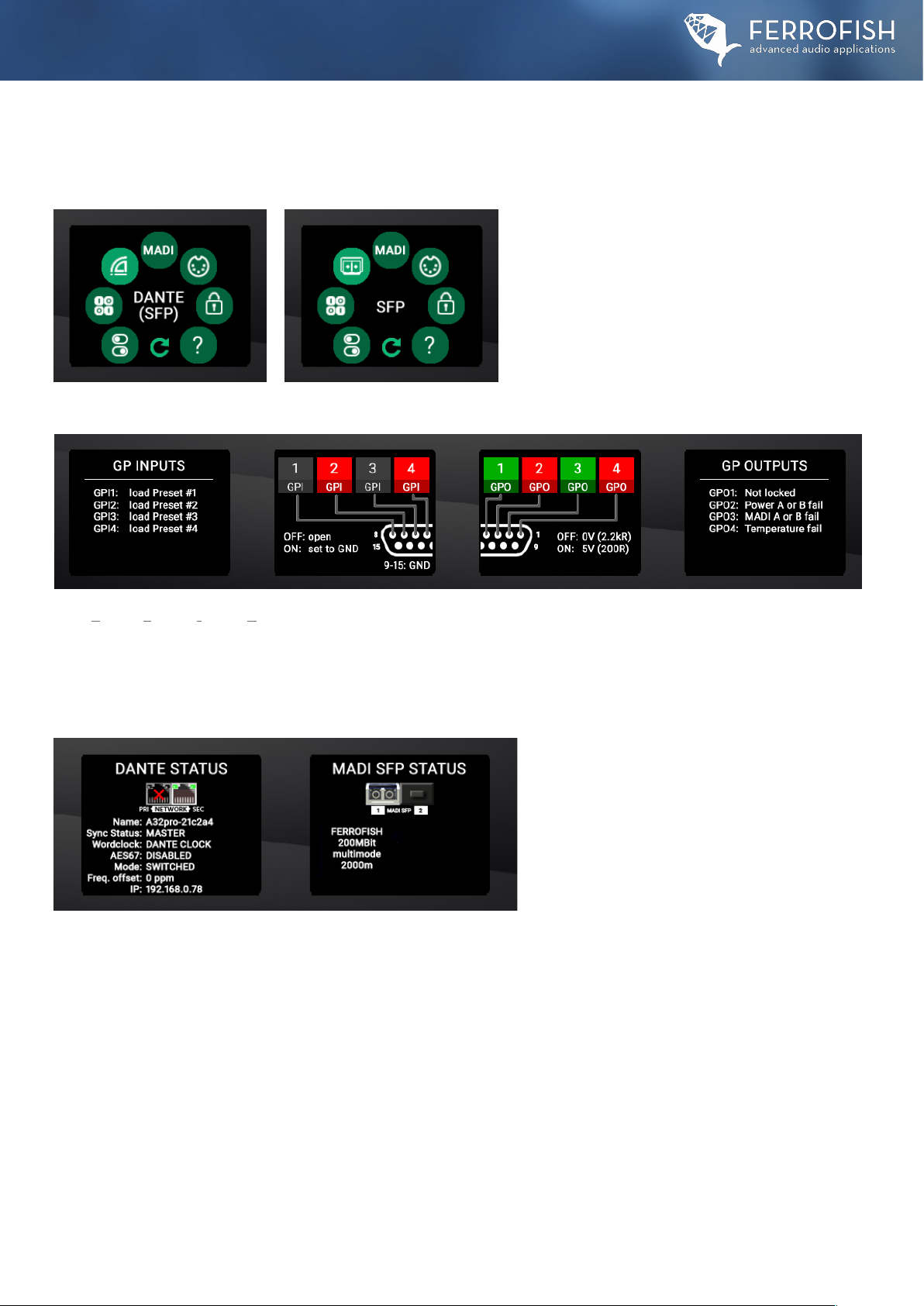
∙GPIO: Loading of presets #1-4 and displaying of alerts.
∙DANTE/SFP: SFP module Infos and Dante Infos*.
∙MADI: MADI SFP Slot Priority Routing.
∙MIDI: MIDI, USB-MIDI and MIDI-over-MADI Routing.
∙LOCK: Locking the front panel.
∙INFO: Further information about the device and the team.
SETUP MENU A32pro Dante
SETUP MENU A32pro
GPIO (General Purpose Input & Output)
In the GPIO menu, you can check the status of all GP inputs and outputs at a glance. In addition, the outputs can also be activated and
deactivated manually via the touch screen.The inputs can only be triggered via the hardware input. The exact functions of the four inputs and
outputs can be found in the chapter of the interface description. Please note that the inputs are always active.
Do not connect the GPIO connector on the inputs if you want to prevent loading a preset by accident.
DANTE (SFP) / SFP INFO
The DANTE / SFP Info Menu displays information about
the internal Dante module* and the installed SFP
modules. Please note that the info screen about the
installed Dante module only appears on an A32pro Dante.
On an A32pro you will only see the info screen for the SFP
modules.
DANTE Status: In the DANTE Status Menu, the following parameters of the internal Brooklyn Board are displayed:
∙Name: Name of the device inside the DANTE network
∙Sync Status: Indicates whether the unit is configured as Master/Leader or Slave/Follower.
∙Wordclock: Displays the wordclock speed.
∙AES67: Indicates whether the AES67 interoperability standard is switched on or not.
∙MODE: Indicates the mode of the rear dual Ethernet port. In SWITCHED, both ports work like a switch, in REDUNDANT, both single ports
are used for single DANTE networks in redundancy mode.
∙FREQ. OFFSET: Indicates the offset of the wordclock in the Dante network in relation to the device’s own wordclock. Values of +/- 100 are normal.
∙IP: Displays the IP address of the A32pro Dante on the Dante network.
MADI SFP Status: The MADI SFP status menu shows the parameters of the installed SFP MADI modules:
∙VENDOR ID: Manufacturer name of the SFP module
∙I/O SPEED: Speed of the SFP module
∙SFP CONFIGURATION: Indicates whether a SingleMode or MultiMode module is installed.
∙SFP FIBER DISTANCE: Displays the maximum usable distance (depending on the configuration).

13
A32pro Series Manual: Main Menu > Setup
48k or 96k frame (only active in SMUX/2 mode - 64-96kHz)
In 48k frame mode, two channels are combined. In this way, the 64 MADI channels are bundled into 32 channels. In 96k frame mode, shorter
frames of 32 channels each are sent directly. Both formats transmit the same number of channels (32), but the 96k frame mode has the
advantage that the receiver can distinguish between SMUX/1 and SMUX/2 operation and switch automatically.
Make absolutely sure that in SMUX/2 mode the frame format is set identically on all devices.
Short frame (56Ch) or full frame (64Ch)
The MADI format in its first version (short frame) had a channel count of 56x56 channels. In addition, the speed of the channels could be shifted
by 12.5% to enable synchronisation with tape machines ("Varispeed"). Later, the MADI format was extended to full frame mode, where Varispeed
was dropped and the freed bandwidth was converted to a higher channel count of 64x64 channels. Make sure that the selection of the format is
identical for all MADI devices.
Latency compensation
In the case of daisy-chaining, a latency of 3 samples occurs at the MADI interface. By choosing the correct position in the chain, this latency is
compensated so that all signals are output coherently again.You can choose between "single device" (only one device), "1 of 2 devices" (first of
two devices) and "2 of 2 devices" (second of two devices).
MADI Input (Priority)
Here you can select the priority of the two MADI SFP ports (1&2) via one of the four presets:
Use SFP1 only - uses only SFP slot 1
Use SFP2 only - uses only SFP slot 2
Use SFP1 with priority - uses SFP slot 1 and switches to SFP slot 2 in the event of an error.
Use SFP2 with priority - uses SFP slot 2 and switches to SFP slot 1 in the event of an error.
MADI SETUP & ROUTING
In this menu you set the parameters of the MADI protocol and
the latency compensation on the left screen and the routing
priority of the two SFP modules on the right screen.
Please note that the routing priority (MADI INPUT) only works
if both SFP modules are installed.
A32pro Dante set to both
In this preset, the two ports are separated from each other. However, the A32pro (Dante) accepts remote control commands from both ports.
A32pro Dante set to MIDI
In this preset, the two MIDI ports are connected and the A32pro (Dante) receives remote control commands from the physical MADI port.
A32pro Dante set to MIDI-over-MADI
In this preset, the two MIDI ports are connected and the A32pro (Dante) receives remote control commands from the MIDI-over-MADI port.
Please note that to use the MIDI-over-MADI control commands you still need a MADI device that supports MIDI-over-MADI.
MIDI ROUTING
In the MIDI menu, you can set the routing of the individual
MIDI ports (physical MIDI port (2x 1/8“ (3.5mm) jacks on the
back of the unit) as well as the MIDI stream from the MADI
signal (MIDI-over-MADI).The MIDI data is embedded in the
user bits of the MADI audio data stream.
There is a choice of three presets:
14
A32pro Series Manual: Main Menu > Setup
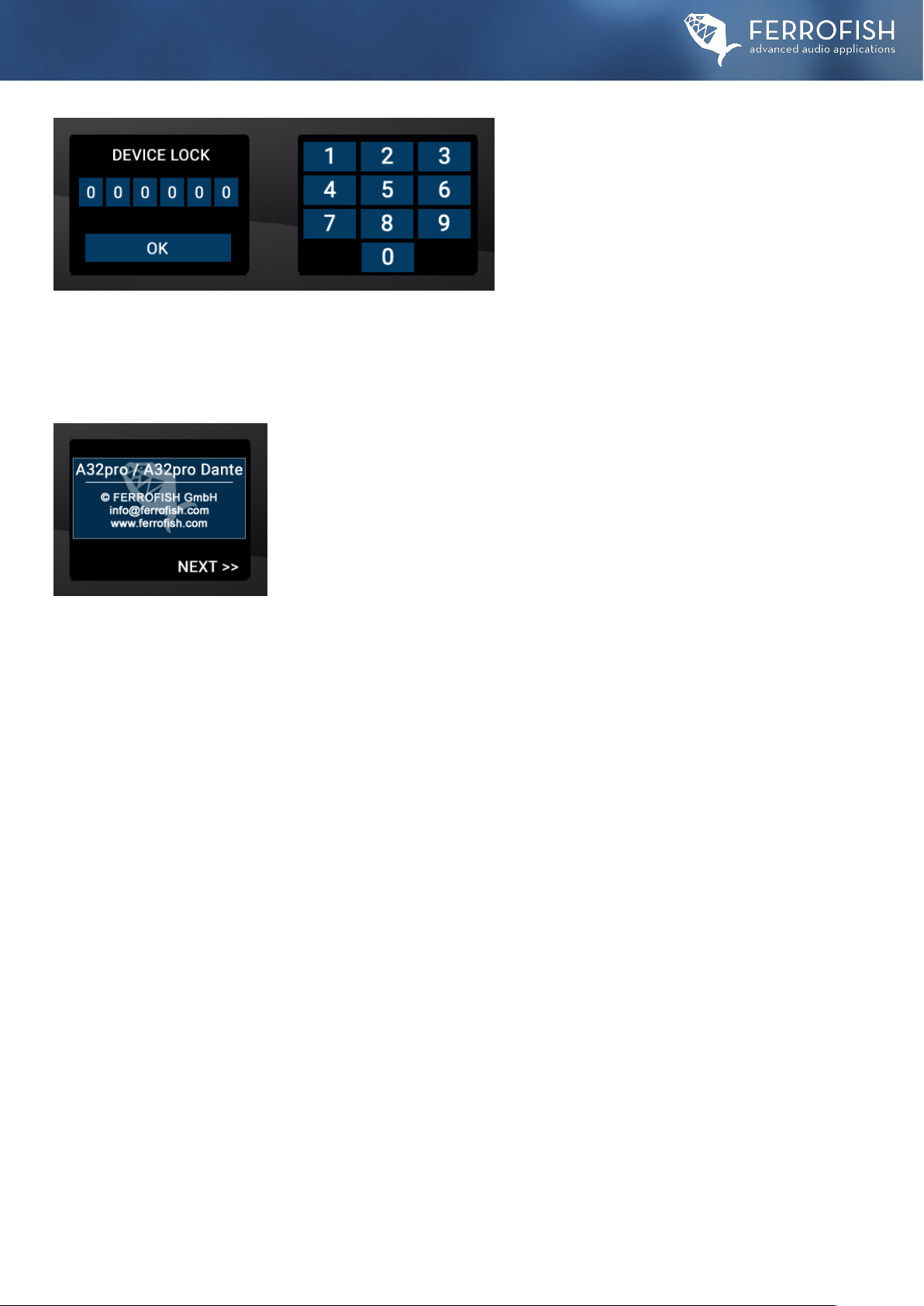
DEVICE LOCK
This menu allows you to lock the control panel of the unit.
When the lock is active only the headphone menu is
accessible. The unit is thus irrevocably locked.
The lock can only be unlocked again with the code
previously provided on the sticker on the bottom of the unit.
Please note:
We strongly advise you to make a note of this code, and to store it in a safe place for future reference.
This code cannot be changed, and a locked device cannot be reset by the user – this requires a recovery code from the manufacturer,
and is subject to a charge.
INFO
In the Info Menu you find additional information about the device and the developer crew. Yay!

15
A32pro Series Manual: Main Menu > Setup > Settings
Main Menu > Setup > Settings
SETTINGS
In the Settings Menu you have access to the following functions:
∙A/D: Selection of the filters of the analog/digital converters.
∙D/A: Selection of the filters and the operating mode for the digital/analog converters.
∙ALERT: Management of alerts for Lock, MADI, temperature and power supply.
∙VISUAL: Here you can adjust the parameters of the displays and the optical displays.
∙BNC: Here the termination of the wordclock input can be switched on or off.
∙DEVELOP: Developers can start and test their own software developments in this menu.
∙CONFIG: Here you can reset the unit or start Vegas Mode.
In general, the group delay is lower with minimum-phase filters than with linear-phase filters.
However, due to their design, linear-phase filters may cause "ringing" (especially with percussive signals).
At 44.1 kHz, the group delay of the filters is all less than 1 ms; minimum- phase filters have the lower group delay.
ADC SETTINGS
In the ADC Settings menu, one of the eight different anti-aliasing filters for the A/D converters can be
selected. The user can choose between minimum and linear phase filter designs:
∙Minimum Phase: Standard / Fast Roll-Off / Slow Roll-Off / Slow Roll-Off Low Dispersion
∙Linear Phase: Apodizing / Fast Roll-Off / Fast Roll-Off Low Ripple / Slow Roll-Off
!
Please note that the chosen filter applies to all A/D channels.
DAC SETTINGS
In the DAC Settings menu, you can choose between two different filters for the DA converters.
A minimum-phase filter and a linear-phase filter are available:
∙Minimum Phase: Standard
∙Linear Phase: Fast Roll-Off Low Ripple
The group delay of all filters is less than 1ms at 44.1kHz.
Please note that the chosen filter applies to all D/A channels.
ALERT
The following parameters can be monitored in the Alert Menu:
∙MADI Alert ON/OFF: When using two SFP MADI modules,
they can be monitored for signal failure.
∙Power Alert: When using two power supplies, they can be
monitored for signal failure.
∙Temperature Alert: An alert is issued when a temperature
limit is reached or exceeded.
In addition, the D/A converter has three operation modes:
The MODE 1 setting gives optimal dynamics and THD+N values. MODE 2 and MODE 3 are alternative settings of the converter, whereby the
measured values are not optimal, but offer a different listening experience. It is recommended to use MODE 1.

16
A32pro Series Manual: Main Menu > Setup
BNC SETTINGS
The BNC wordclock input is internally terminated in the hardware with a 75 Ohm resistor. In normal
daisy- chain wiring (wordclock out of unit#1 to wordclock in of unit 2, wordclock out of unit#2 to
wordclock in of unit#3, etc.), you should always leave this termination switched on if your FERROFISH
device is the last unit in the wordclock chain. In case of cabling with BNC T-connectors, the
termination should be switched off. In this case, the termination is usually done by an extra
termination BNC end-cap.
DEVELOP MODE
In DEVELOP mode, external developers can test their own plug-ins and software developments on our
hardware platform. However, this requires a Software Development Kit (SDK) from FERROFISH.
Without this kit, an error message appears on the screen.
This is normal and does not indicate a malfunction of the unit.
VISUAL SETTINGS
Here you can determine the behavior of the encoder LED,
the LED in the power button and the brightness of the displays.
Power LED: Determines the state of the POWER button's LED
when switched off:
Off, pulsating (xfade) or dimly glowing (dimmed)
Alert Ring: Here you determine the behaviour of the white light corona of the encoder in the event of an alert: On, one of three flashing modes.
(flashing 1-3) or one of four pulsating appearances (xfader 1-4). An "off/off" mode does not exist here for safety reasons - to switch off the alert
LED entirely, disable this option in the ALERT menu.
In the left screen, the general brightness of the displays can be set as well as the display behaviour of the brightness related to time:
Ramp up when event 15s: The brightness is ramped up to the maximum brightness when the display is pressed and after 15s it is ramped
back to the brightness set in the upper row.
Keep dimmed: The brightness of the display is kept at the level selected above.
A32pro Series Manual: Main Menu > Setup > Settings
CONFIG / MISC. CONFIGURATION
In the CONFIG menu, the unit can be reset to the factory settings or the so-called Las Vegas
mode can be started.
Factory Reset: This resets the unit and sets all settings to default.
ATTENTION: THE FACTORY RESET RESETS ALL SETTINGS OF THE UNIT INLCUDING THE PRESETS!
So please make a note of any important settings before resetting the unit.
Las Vegas Mode: Displays a wave-like movement of the I/O meters for demo purposes.

17
A32pro Series Manual: Remote Control / Cascade Operation
Remote Control
Remote control via RemoteFish App (PC / Mac)
The A32pro Dante can be completely remote controlled via the RemoteFish app. The connection can be controlled either via the USB socket (MIDI-
over-USB), MADI (MIDI-over-MADI), the MIDI I/O ports of the unit (via a separate MIDI interface) or via Dante* (Remote-over- Dante). In principle,
all functions that can be controlled via the front panel can also be controlled via the RemoteFish app.
(* A32pro Dante only)
For some applications, the 32x32 channels may not be sufficient. Likewise, both Dante and MADI offer a channel count of 64x64 channels
per cable at single sample rates (SMUX/1). To "fill" this channel count completely, several A32pro (Dante) units can be cascaded.
In the MADI network, this is done by daisy-chaining or, in rare cases, in star topology. In the Dante network, star cabling is used as standard
to connect to an Ethernet network switch.
Cascade operation via MADI
Equipping the unit with a maximum of two SFP modules results in a wide range of possible application scenarios. A MADI connection offers
64 channels in each direction at a sample rate of up to 48 kHz (SMUX/1 operation). Due to a limited bandwidth, the number of channels is
halved with SMUX/2 (64 to 96kHz), as two channels are bundled to transmit a 96kHz channel.This is called multiplexing. With SMUX/4 (128
to 192kHz) four channels are multiplexed to transmit one 192kHz channel, reducing the number of channels to 16x16. Generally possible
with MADI is cabling in star topology as well as in series (daisy-chain). Which type of cabling makes sense depends on the respective
application. For a star topology, the other device must have several MADI I/O ports. This would make sense, for example, if you were
recording at 192kHz, because then all available channels (16x16) of a MADI I/O port would be occupied. So when using two A32pro
units at 192kHz, you need another MADI device (e.g. MADI Audio Interface) with two MADI I/O ports.
Wiring in series (daisy-chain) therefore only makes sense with sample rates in SMUX/1 mode (up to 48kHz), where you can use the
remaining free channels for the next unit(s) in the chain. When MADI is wired in series at up to 48kHz (SMUX/1), a maximum of two
A32pro units can be connected in series. At higher sample rates daisy-chaining is no longer possible due to the limited bandwidth of the
MADI format. As the A32pro Dante has two SFP slots (so-called cages), the MADI data stream can be distributed over two ports.
This can be interesting for redundancy purposes as well as for scenarios with extended routing.
The A32pro series can be remotely controlled in several ways:
Remote control via MIDI CC
As an alternative to operation via the front panel or the RemoteFish app, the unit can be controlled via simple MIDI CC. Remote control can be
done via USB (MIDI-over-USB), MADI (MADI-over-USB) or the MIDI I/O ports of the unit.
The assignment of the MIDI messages to the most important control parameters of the A32pro Dante can be found in the appendix.
Cascade Operation
Cascading multiple A32pro (Dante) units

18
A32pro Series Manual: Cascade Operation / Troubleshooting
Cascade operation via Dante
Cascading of Dante units is done in star topology due to the network structure of Dante. A series connection via the PRI/SEC sockets is
technically possible, but Audinate does not recommend it. A DANTE-compatible network switch is usually used as the star point. In this case,
a series connection is not necessary, although most Dante units have a double network socket. However, this should only be used for
redundant operation. In this case, two separate identical Dante networks are connected to both network sockets (PRI and SEC). If one of the
Dante networks fails, the system automatically switches to the second network. This switching takes place directly in the Brooklyn module
and cannot be influenced externally.
Troubleshooting
Various problem scenarios with approaches to solutions.
Scenario #1: The unit cannot be switched on
In this case, check the power supply and also connect it to the second PSU input of the A32pro (Dante) as a test.
Also check the output voltage of the power supply under load and replace it if necessary.
Scenario #2: The signal seems to arrive in the unit, but it does not come out at the intended channel.
First, go to the menu of the headphone listening matrix and select the interface and channel number on which you expect the incoming
signal. If you do not hear the signal there, please check the cabling to the unit and the signal source from which the signal should come as
well as the clock settings of the A32pro Dante. If you can hear the signal in the headphone monitoring matrix, check the ROUTING, GAINS
and LEVELS settings. If this does not help, please perform a factory reset.
Scenario #3: My signal has periodically constant dropouts (on-off-on-off...)
Periodically regular dropouts often indicate an attempt to link two units in INTERNAL/MASTER/LEADER mode. Since there can only be one
unit in a digital network of several units that sets the clock (INTERNAL/MASTER/LEADER unit), all other connected units must be set to
SLAVE/FOLLOWER. Please note that the A32pro Dante does not come with sample rate converters (SRC) by default that would allow
operation with multiple units set to wordclock master.
Scenario #4: The signal on the headphones is relatively quiet/weak even in the "full" position.
Make sure that the gain level in the Headphone Setup Menu is set to 0dB.This is the loudest possible level of the headphone preamplifier.
When changing to another system (e.g. IEM) or one with lower impedance and / or higher sensitivity, make sure to set it to a lower value
beforehand!
When daisy-chaining two A32pro (Dante) units via the MADI interface at single sample rates, the MADI channels 33-64 must be routed
„passthru“ to the second A32pro (Dante) in the routing menu of the first device. The settings would be:
MADI Routing Unit #1
MADI Routing Unit #2
In this configuration, MADI I/O channels 1-32 of unit #1
in the chain are routed to the analog I/Os.
At the same time, the MADI input channels 33-64 of unit #1
are routed through to the MIDI output channels 33-64
so that they can be used on unit #2.
On unit #2, the MADI I/O channels 33-64 are routed to the
analog I/Os 1-32. Thus, all 64x64 analog audio
channels of both A32pro units are available.

19
A32pro Series Manual: Technical Specifications
Technical Specifications
FERROFISH A32pro (Dante) - 32x32 + 2+ 4 A/D-D/A signal- and format converter
MADI I/O!
(AES10)
Dual SFP slot for SFP MADI modules, equipped with one SFP module as standard, optical in MultiMode.
64 channels @32kHz, 44.1kHz, 48kHz
32 channels @64kHz, 88.2kHz, 96kHz
32 channels @128kHz, 176.4kHz, 192kHz*
* Parallel operation of both SFP modules for 32+32 channels at
192kHz MIDI over MADI implementation
Latency: 3 samples
Automatic switching between both SFP slots in case of signal loss of one signal branch.
ADAT I/O
4 + 4 optical interfaces
32x32 channels @32kHz, 44.1kHz, 48kHz
16x16 channels @64kHz, 88.2kHz, 96kHz
8x8 @128kHz, 176.4kHz, 192kHz
Latency: 3 samples
GPIO
General Purpose Input & Output to dSub15 female connector.Trigger inputs: Set input pin to ground.
Outputs: 5V, 10mA max for connecting an LED, optocoupler or similar.
DANTE
64 x 64 Audinate Brooklyn Board integrated. 2 standard ethernet connections (Pri/Sec).
Wordclock
BNC jack IN & OUT, 75 ohms termination of the input switchable in the unit
MIDI I/O
2x 1/8“ (3.5mm) jack sockets for MIDI IN and MIDI Out, adapter to MIDI 5Pin available from FERROFISH.
Pin assignment follows the MIDI 2.0 Type A standard.
A/D converter
32Bit ESS A/D converter, latest generation
Outputs!
(analog)
4 x D-Sub25, female / Tascam® standard
Maximum output level: +20dBu
Digital gain 0dB...-28dB in 1dB steps
D/A converter
32 Bit ESS D/A converter, latest generation.
MAIN OUT!
(analog)
2x balanced 1/4“ (6.35mm) jacks with separate HP amp on dedicated ESS DAC (same as headphones).
Main Out reproduces the signal of the red headphone output.
Inputs!
(analog)
4 x D-Sub25, female / Tascam® standard
Maximum input level: +20dBu
Digital gain: 0dB...+28dB in 1dB steps
Op-Amps
OPA1604 and OPA1664.
Display
4x color TFT screen 3" and capacitive multi-touch over the entire screen and FERROFISH logo area.
USB
USB-B connector with USB2 protocol for MIDI-over-USB (class compliant).
Headphones
2x 6.3mm jack output, gain adjustable in four steps, digital volume adjustment in 1dB resolution.
Operating mode selectable between dual stereo (unbalanced) and balanced.
Dedicated monitoring path on separate 32Bit ESS DAC in stereo mode (like Main Out).
DSP
SHARC DSP ADSP-2148x series built-in, expandable via optional propietary DSP stick modules.
PLL
Digitally controlled PLL with active jitter reduction
Output jitter: 50ps ... 100ps typ.

20
A32pro Series Manual: Technical Specifications / CE Conformity
Internal
wordclock
Temperature compensated oscillator (TCXO) with high accuracy.
Initial accuracy:+/- 1.5ppm
Course during temperature range: +/- 2.5ppm
Aging: +/- 1ppm
Voltage supply
12V at maximum 3A. 2 x sockets for 2.54mm hollow plug with securing nut for optional redundant power supply.
Input voltage monitoring selectable, warning message and/or GP output in case of failure of a voltage source.
Fuse
Polyfuse, internal, self-resetting
Power supply
12V, 3A, center pin positive , 01x PSU included
Power requirement
24VA nominal, less then 1VA in standby mode.
Temperature range
+5° to +45° Celcius - +41° to +113° Fahrenheit
Humidity
< 75%, non-condensing.
Weight
3,5kg - 7,71 lbs.
Dimensions
Net size: 25.3cm x 44.4cm (19") x 4.4cm (1U) (D x W x H)
Gross size: 29cm x 48.3cm x 4.4cm (1RU) (D x W x H) (including connectors, rack ears and knobs)
EMV
This unit has been tested by a test laboratory and complies with the standards for the harmonization of the laws of the member states
relating to electromagnetic compatibility (EMC Directive 2014/30/EU) as well as DIN EN 55103-1 (EMC interference emission) and
DIN EN 55103-2 (EMC interference immunity).
RoHs II
Each appliance has been soldered lead-free and complies with the requirements of the EU Directive 2011/65/EU and the limit values defined
therein for hazardous substances in electrical and electronic equipment.The documents on which this declaration is based are held by the
manufacturer and can be viewed there at any time. Unauthorized modification of this product invalidates the validity of this CE declaration!
FCC declaration
This device complies with Part 15 of the FCC rules. Operation is subject to the following two conditions:
(1) The unit may not cause any interference, and
(2) The unit may be immune to any interference received, including interference that may cause undesired operation.
CE Conformity
This manual suits for next models
1
Table of contents
Other Ferrofish Media Converter manuals

Ferrofish
Ferrofish Verto 32 User manual

Ferrofish
Ferrofish Verto 32 User manual

Ferrofish
Ferrofish A32 DANTE User manual

Ferrofish
Ferrofish A16 AE User manual

Ferrofish
Ferrofish A16 MK-II User manual

Ferrofish
Ferrofish PULSE16 DX User manual

Ferrofish
Ferrofish PULSE 16 User manual

Ferrofish
Ferrofish A32 DANTE User manual


