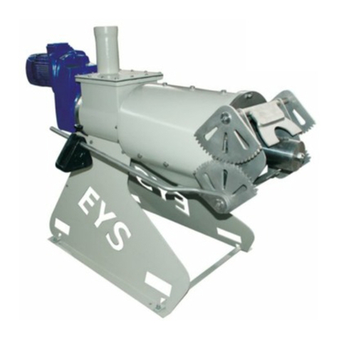
EYS SP series User manual

USER MANUAL
“SP” SERIES
EYS SCREW PRESS SEPERATORS
SP400
SP600
SP800
SP600HD
SP800HD
JAN 2012

Congratulations on your purc ase of t e EYS Screw-Press Separator!
We are glad that you chose EYS separator or your solid-liquid separation solutions and are con ident that
you will be more than satis ied with your purchase.
This manual is intended to provide basic in ormation about the operation o the EYS Separator, and to point
out to main areas o consideration while operating and maintaining the machine. Please read this manual
care ully be ore operating the machinery, and keep it in an easily accessible place or uture re erence. I
any o your questions or concerns are not covered in this manual, please contact the respective dealer who
had installed the machinery. Your dealer’s contact in ormation is:
I you are not able to reach your dealer and in need o immediate support, then please contact EYS directly
at:
EYS Metal Sanayi ve Ticaret Ltd. Şti.
ASTIM Org. San. Bol. Hurriyet Ma . Havaalanı Bul. No:233, Tepecik/AYDIN - 09100 TURKEY
Tel: +90 (256) 231 05 98
231 11 38
231 05 76
Fax: +90 (256) 231 11 01
e-mail: [email protected]
internet: www.e-y-s.com
Apart rom providing technical and operational instructions, this manual also includes certain sa ety
warnings that must be ollowed by the user. T e safety instructions and warnings listed in t is
manual are by no means a complete list of all safety concerns associated wit operating t e
mac ine. Users must apply common sense and abide by t e general safety guidelines t at govern
operating of mac inery.
Contents o this manual re er to the latest product models currently in production at the time o
preparation o the document. EYS reserves the right to make changes in the product design at any
time.
Care ully ollowing the instructions set orth in this manual are essential or maintaining operator
sa ety as well as the longevity and e iciency o the machinery. Dealers must provide a copy o this
manual to the customer along with the purchased product.

“SP SERIES” USER MANUAL
Page 3 / 34
Please make sure that the operator in charge o operating and/or maintaining this product has ull
access to this manual and that he/she has read it entirely prior to running or servicing the machine.
Also please record your product model number and serial number rom the machine’s in o-tag to the
ollowing section. These in o will be necessary and use ul when ordering replacement parts in the
uture.
Congratulations again on your purchase o the EYS Screw Press Separator!
PRODUCT INFO
Product : Screw Press Separator
Model : SP400 SP600 SP800 SP600HD SP800HD
Serial Number :
Dealer :
Adress :
Tel :
Fax :
Installation Date :
Manufacturer : EYS METAL SANAYİ VE TİCARET LTD. ŞTİ.
ASTİM ORGANİZE SANAYİ BÖLGESİ, HÜRRİYET MAHALLESİ, HAVAALANI BULVARI
NO:233, TEPECİK, AYDIN, TÜRKİYE
TEL: +90 (256) 231 05 98, 231 11 38, 231 05 76, 231 05 77
FAX: +90 (256) 231 11 01
internet: www.e-y-s.com

“SP SERIES” USER MANUAL
Page 4 / 34
HAND-OVER FORM (TO BE SIGNED OFF BETWEEN THE DEALER AND THE CUSTOMER)
Product : SCREW PRESS SEPARATOR
Model : SP400 SP600 SP800 SP600HD SP800HD
Serial Number :
Dealer :
Adress :
Tel :
Fax :
Installation Date :
Manufacturer : EYS METAL SANAYİ VE TİCARET LTD. ŞTİ.
ASTİM ORGANİZE SANAYİ BÖLGESİ, HÜRRİYET MAHALLESİ, HAVAALANI BULVARI
NO:233, TEPECİK, AYDIN, TÜRKİYE
TEL: +90 (256) 231 05 98, 231 11 38, 231 05 76, 231 05 77
FAX: +90 (256) 231 11 01
internet: www.e-y-s.com
This form confirms that the product installation and start-up has been completed
successfully. Basic training has been provided and this manual has been handed over to
the responsible personnel below.
Responsible person on behal o
the dealer/distributor
(date and sign)
Responsible person on behal o
the customer
(date and sign; please print name)
ATENTION !
Manu acturer’s warranty is not valid unless this orm is signed and
dated upon installation!

“SP SERIES” USER MANUAL
Page 5 / 34
INTRODUCTION
Signs And Definitions
The CE sign designating
con ormance with the relavant speci ic EC
Directives as well as the General Machinery Directive, has been
marked on the product by the manu acturer.
WARNING!
This warning box is used to highlight sa ety related precautions
throughout the document. Remember that there is risk o personal
injury with every “warning” sign topic and it is o utmost importance
to understand and ollow the contained instructions care ully.
ATTENTION !
Failure to ollow instructions can result in damage to a part or the
whole o the machine, possibly putting the machine out o
commission.
NOTE !
It is especially important to understand and implement the
instructions highlighted therein or the success ul long-term
operation o the machine.
Qualified Operators should be properly trained in their assigned area o responsibility, be
knowledgable about general machinery handling precautions and related hazards/risks, capable o
oreseeing and preventing potential damages to the machine be ore they happen, and be able to apply
necessary irst-aid practices as necessary.
Operational Responsibility
Responsibility o operating the machine in accordance with its intended purposes lies with the
customer. The manu acturer is not in anyway responsible or any damages that may be caused by
inappropriate handling o the waste streams resulting orm the operation o the product. Likewise, the
manu acturer can not be held responsible or any damages resulting rom the use o un-approved
and/or non-original spare parts on the machine.
Second- and Owners ip
In the case o trans er o ownership o the product to a new customer, the original owner is responsible
or handing over this user-manual to the new owner. New owner must be in ormed and trained about
the basic operation o the product accordingly.
Operational Liability
The entire liability o operating the product properly lies with the customer. The customer is
responsible or making sure that the product is used in accordance with the guidelines set orth in this
document, plus other general machinery operating rules that may not be covered here but are
expected to be known by any machinery operator. The maximum liability o the manu acturer in any
event can not exceed the monetary value o the product itsel .

“SP SERIES” USER MANUAL
Page 6 / 34
CONTENTS:
1 SAFETY INSTRUCTIONS………………………………………………………………………………………………… 7
2 GENERAL INSTRUCTIONS……………………………………………………………………………………..……… 8
2.1 Working with slurry………………………………………………………………………………………...….…… 8
2.2 Proper operation…………………………………………………………………………………………..….…….. 8
3 OPERATION PRINCIPLE…………………………………………………………………………………….……….…. 8
4 INSTALLATION & START-UP....………………………………………………………………………..………….… 9
4.1 Delivery ………...............…..………………………………………………………………………………………. 9
4.2 Handling.......………………………………………………………………………………………………..……….... 9
4.3 Typical installation........…………………………………………………………………………………………... 10
4.4 Setup & installation…………………………………………..…………………………………………………….. 10
5 PRE-START-UP CHECKS............................................……………………………………………………… 12
6 START UP…………......................……………………………………………………………………………………… 12
6.1 Counter-pressure on discharge doors…..…………………………………………………………………. 12
6.2 Establishing the solid plug…….....……………………………………………………………………………… 12
6.3 Plug adjustment………………………………………………………………………………………………………. 13
6.4 Other points o consideration...............…………………………………………………………………… 14
7 TROUBLESHOOTING..............................................................…………...………………………….. 16
8 STOPPING THE SEPARATOR…..………………………………………………………………..………………….. 19
9 LONG TERM STORAGE OF THE SEPARATOR…......………………………………………………………… 19
10 CHECKING THE SCREEN AND THE SCREEN GUIDE-RAILS…….…………………..…………………… 19
11 CHECKING THE AUGER……….....……………………………………………………………………………………. 20
12 ACCEPTABLE WEAR AND LIMIT TOLERANCES……………………………………………...……………… 21
13 DISASSEMBLY AND ASSEMBLY…….….…………………………………………………………………………… 22
13.1 Disassembly…..………………………………………………………………………………………………………… 22
13.2 Assembly…..…………………………………………………………………………………………………………….. 23
14 GENERAL MAINTENANCE…………………………………………………………………………………………….. 24
15 STORAGE…….......………………………………..……………………………………………………………………….. 25
16 TECHNICAL SPECIFICATIONS……………....…………..………………………………………………………….. 25
16.1 Technical speci ications o the separator……...………………………………………………………… 25
16.2 Machine tags……...........…………………………………………………………………………………………… 27
16.3 Warning signs……....………………………………………………………………………………………………… 27
17 ELECTRIC CONTROL PANEL………......……………………………………………………………..…………….. 28
17.1 Wiring diagrams………………………………………………………………………………………..……………. 28
17.2 Reverse-run o auger at start-up…….......................................……………….......…………… 28
18 SPARE PARTS LIST………......………………………………………………………………………………………….. 29
19 MANUFACTURER’S WARRANTY …....…………....……………………………………………………………. 29
20 EC DECLARATION OF CONFORMITY ………...…….…………………………………………………………… 30
EXHIBITS (Spare Parts List; Wiring Diagrams)………............................................…………… 31-

“SP SERIES” USER MANUAL
Page 7 / 34
1SAFETY INSTRUCTIONS
C eck conformance wit safety instructions prior to eac start-up!
1. In addition to the speci ic instructions contained in this document, general machinery operating
rules and precautions must be ollowed!
2. Sa ety related signs are marked on the product as necessary. These signs and stickers are
important or personal sa ety, so do not remove them!
3. Do not operate the machine be ore replacing/installing all sa ety and protection related
parts/covers!
4. Make sure you understand the general unctioning principle o the machine be ore operation!
5. Put on relatively snug operational out it when operating the machine. Loose out its and long
sleeves can get caught by the moving parts during operation and servicing.
6. Slurry can emit lammable gases under certain conditions; so avoid smoking or carrying open ire
near the machine!
7. Machine should be installed at a properly ventilated area. Avoid spending long periods o time in
poorly ventilated areas around the slurry!
Maintenance
1. Never per orm any maintenance, service or cleaning be ore ully stopping the machine and the
other system components.
2. Always check and veri y that the bolts/nuts on the machine are securely tightened.
3. Always wear work gloves when handling sharp and metal objects during maintenace.
4. Always observe local regulations when disposing o lubricants/grease, etc.
5. Never work on the control panel and/or electrical connections without ully cutting o the power
irst.
6. Only manu acturer approved spare parts must be used or repairs and replacements.
2GENERAL INSTRUCTIONS

“SP SERIES” USER MANUAL
Page 8 / 34
2.1 Working wit slurry
WARNING !
Slurry can emit lammable and nauseus gase
s
. Always ensure that
there is proper ventilation in the operation area.
2.2 Proper Usage
EYS screw press separator is designed to separate solid and liquid phases o iber-rich waste materials.
The waste should be ree o sand, as well as other oreign objects such as metal, glass, wood, etc. that
have the potential o damaging the internal parts o the separator.
3OPERATION PRINCIPLE
Slurry can be ed into the EYS Separator either by a pump or gravimetrically through a hopper at the
inlet. The auger inside the separator moves the slurry orward rom the inlet section towards the solids
discharge outlet. During this travel o the slurry, the cylindrical screen around the auger continously
dewaters the liquid raction o the slurry and channels it out through the liquid discharge outlet.
Meanwhile the dewatered solids orm into a irm plug as they get closer to the discharge area. At the
solids discharge outlet, there are two hinged doors that apply constant pressure to the solid plug by
means o counterweights attached to the arms that regulate the angle o these doors. As the auger
urthers the solid plug orward, the plug overcomes the backpressure applied by the discharge doors
and exits the machine rom the discharge outlet.
1. Slurry inlet
2. Auger
3. Screen
4. Solid plug
5. Separated solids discharge
6. Separated liquid discharge
Operational e iciency o the separator (throughput and dryness o solids) is greatly a ected by the
slurry consistency. There ore per ormance results may vary depending on what kind o slurry is being
dewatered. Following principles should be kept in mind when optimizing per ormance.
•Separation e iciency is typically increased when a larger screen slot-size is used. This in turn
will result in more solid particles to escape into the separated liquid phase.
•Smaller screen slot-size typically results in less solids percentage in the separated liquid phase.
However throuhput will be lower with smaller screen slot-sizes.
•Moisture content o the separated solids is typically reduced with increased back-pressure at
the discharge doors.
4INSTALLATION AND START-UP

“SP SERIES” USER MANUAL
Page 9 / 34
4.1 Delivery
EYS Seperator is delivered ully assembled; in a secure crate. Net weight o each model is as ollows.
SP400
SP600
SP800
SP600HD
SP800HD
Net Weig t [kg]
450
700
850
950
110
0
4.2 Handling
The machine must be handled and li ted with a sa e and proper method as required by the speci ic
circumstances o the installation location. A suitable crane and/or orkli t must be utilized. Please
re er to the above igure or proper li ting arrangements by orkli t or crane.
WARNING !
A properly chosen orkli t can be used or trans erring and/or li ting o the
separator to short distances or heights. Use the speci ically designed orkli t
openings on the legs o the separator. Make sure that the orks o the orkli t
are ully through these openings on both legs. A crane should be employed
when li ting the separator to higher locations (such as while installing on an
elevated plat orm). When li ting with a crane, use two slings o 3m length and
1ton li ting capacity each, together with proper shackles. Apply the slings as
shown in the above igure. Never li t with chain or steel cable. These li ting
procedures must be ollowed not only or initial installation but or subsequent
li tings also, whenever necessary.
4.3 Typical Installation

“SP SERIES” USER MANUAL
Page 10 / 34
1. Separator
2. Inlet pipe ( rom
pump)
3. Over low pipe
4. Air-vent pipe
5. Solids cover
(optional)
6. Liquid e luent
drainage pipe
7. Pump
8. Pump inst. ixture
9. Agitator & inst. pole
10. Slurry pit
11. Liquid e luent pit
12. Separator plat orm
13. Electric control
panel
4.4 Set-up and Installation
ATTENTION !
Separato
r
should be installed at a reasonable height to allow separated solids
to accumulate easily underneath. Otherwise the separator may become buried
under accumulated solids.
The separated liquid raction will be drained to a separate lagoon (other than
the slurry pit where the separator is being ed rom) gravimetrically. There ore
this lagoon should be planned close to the separation system in order to allow
or easy drainage o the liquid.
Follow the below steps or setting up the separator:

“SP SERIES” USER MANUAL
Page 11 / 34
•Mount the F-Pipe to the inlet pipe o the separator.
•Mount the pump outlet pipe to the 6” upper inlet o the F-Pipe using the quick coupling
connectors.
•Mount a 6” over- low pipe to the lower branch o the F-Pipe using the quick coupling connectors.
This over low line will go directly back to the slurry pit where the pump is.
•Connect the 1,5” air-vent pipe to the over- low line. This line will prevent a possible vaccum e ect
on the over- low line. This air-vent pipe should extend at least 1m above the upper branch o the
F-Pipe (pump line). Make sure that the valve on the air-vent pipe is ree and open.
•Mount a 6” pipe to the liquid discharge outlet o the separator. This pipe will extend to the
separated liquid lagoon. The layout o this pipe should not cause dips along the path, which would
prevent the liquid to drain completely and may cause reeze-ups in the pipe.
•All electric work and connections must be carried out by a quali ied electrician.
ATTENTION!
Over low and separated liquid drainage lines must extend in a linear ashion to allow
easy low o the slurry. Over low line must not be submerged into the slurry pit,
otherwise it might creaate siphoning e ect and divert all slurry low rom the pump
back into the same pit through the over low line.
ATTENTION !
I the pump eeding the separator is not an EYS pump, then a suitable pump must be
used to supply the minimum low rates as per the below table. Otherwise the

“SP SERIES” USER MANUAL
Page 12 / 34
separation e iciency will be compromised. Pipe diameters should not be lower than
4” in order to minimize headloss.
SP400
SP600
SP800
SP600HD
SP800HD
Recommended
Pump Capacity
[m3/ ]
20 50 75 20 50
5PRE-STARTUP CHECKS
•Check the oil level in the gearbox, add the appropriate amount i necessary. Make sure the oil cap
is in place on the gearbox.
•Check that all piping connections are securely in place and ree o any obstacles.
•Adjust the motor protection relay to the recommended value ( actory settings or EYS supplied
control panels are: 4,4A or 2.2kW motor, 11A or 5.5kW motor, 22A or 11kW motor). The auger
o the separator turns counter-clockwise during separation. However with each start-up, the auger
irst turns in clockwise direction (backwards) or 5 seconds in order to releave any excess pressure
on the gearbox due to potentially stuck solid plug inside the machine rom the previous run.
•Remove t e counterweig ts from t e arms to minimize t e counter pressure.
ATTENTION !
Make sure that the slurry pit where the separator is being ed rom is ree o oreign
ojects such as sand/metal/wood pieces that can harm the machine. The slurry pit is
an essential part o your separation system. Such oreign objects can cause
signi icant damage to auger and the screen o the separator, and abrasive materials
such as sand would wear out these two parts very quickly also.
6START-UP
ATTENTION !
It is essential to mix the slurry in the slurry pit thoroughl
y prior to starting the
separator. Lack o proper agitation in the slurry is one o the main causes o low
separation e iciency. Agitation needs to be done prior to start o pumping so that
homogenous material is pumped to the separator.
6.1 Counter-pressure on disc arge doors
The consistency and dryness o the solid plug is adjusted by the positioning o the counter-weights on
the separator arms. Counter-pressure is increased as the weights are moved outwards towards the
open end o the arms.

“SP SERIES” USER MANUAL
Page 13 / 34
ATTENTION !
W
ith each adjustment o the counter
-
pressure, the results will change a ter a minute
or two. T erefore please wait for a couple of minutes after eac adjustment to
observe t e c ange in solids output.
6.2 Establis ing t e solid plug
The solid plug will orm soon a ter the separation system is started. First run-and-stop the pump or a
couple o seconds. Then wait until no slurry remains in the pipes, and repeat the procedure again. A ter
3-5 repeats, the plug will have established and solids will start coming out o the discharge end.
An alternative practice is to irst open the discharge doors care ully and manually ill the space behind
the doors with straw or newspaper as a temporary plug. Then the separator and the pump can be
started up in sequence. The plug will orm shortly a ter start up.
6.3 Plug adjustment
If the plug is too dry,
Push the counterweights orward or remove
some o the counterweights.
I the plug has dried up inside the separator
or a long time, it may stall the separator.
Always arrange the counterweights
symettrically on both arms o the separator.
If the plug is too wet,
Push the counterweights backward to apply
higher counter-pressure on the discharge
doors. I not enough, add on more
counterweight on each arm.
I the plug gets too loose, the plug may
breakdown and when that happens, liquid
slurry would shoot out rom the solids
discharge. In that event stop the system and
re-start ollowing the start-up procedures.
Making these adjustments will be necessary to reach optimum separation e iciency with a given
slurry consistency. Adjustments may need to be ine-tuned when the slurry consistency changes
signi icantly due to heavy rain, etc.

“SP SERIES” USER MANUAL
Page 14 / 34
6.4 Ot er points of consideration
Over low line back to the slurry pit must allow ree low o slurry within at all times.
Make sure that the over low line is ree o any obstacles and is not clogged and/or rozen
!
In
regular operation, over low line should be about 1/3 illed with slurry.
Excessive pump thoughput into the separator may lower separation e iciency.
I the pump chosen or the separation system delivers too high a low, the slurry inlet into the
separator should be regulated with a valve on the inlet pipe.
Open end o the over low pipe must not be submerged into slurry in the slurry pit; as this situation
would create a siphoning e ect and all the slurry being pumped through the separator inlet pipe would
then low back into the slurry pit, preventing the slurry rom lowing into the separator.
Over low and liquid slurry drainage lines should not be exposed to conditions that might change their
diameters (such as a vehicle driving over the line, other weights being applied on them, etc.). This
would increase the pressure inside the pipe and may cause the plug to shoot out rom the separator.
In installations where two (or more) separators are installed side by side, one larger capacity pump can
be used instead o individual small pumps or each separator. In those instances, a collector bu er
tank can be arranged above the separators and a single pump can eed this collector, rom which the
individual separators would be ed. A level control sensor would be use ul in the bu er collector.
Slurry inlet pipe o the separator should not be smaller than 4” (Ø100mm). The inlet pipe should
maintain a constant diameter throughout its length. I these conditions can not be maintained, then
use o a bu err tank above the separator and eeding the separtor rom this tank would be
recommended.
Make sure t e slurry is fully mixed prior to separation. This will prevent rom loss o solids plug
unexpectedly due to very thin slurry input, or stalling o the separator motor due to very thick slurry
input. I the slurry pit very small (e.g., smaller than 100m3), then avoid over-agitation as this may
change the iber structure o the slurry and make the slurry less separable.
The separator should be installed as close to the slurry pit as possible, in order to maintain the optimum
piping layout and minimize rictional losses inside the pipes. Layout o the pipes become particularly
important in situations where the horizontal distance between the separator and the pit is more than
10m. Make sure that the slurry pump line and the over low line extend rom the separator to the slurry
pit always with a downward inclination.
The separated liquid discharge o the separator is 4” (Ø100mm). Sthe liquid drainage line rom the
separator to the separateed liquid lagoon should be a minimum o 4” (Ø100mm). In order to avoid
spihoning e ect on this line, or to prevent reezing o slurry inside the pipe, or to avoid blockage as a

“SP SERIES” USER MANUAL
Page 15 / 34
result o solids settlement inside the pipe, make sure that the line extends rom the separator to the
liquid lagoon with a vertical inclination throughout its length.
In extremely cold climates, the pipelines can be wrapped with thermal insulation materials to prevent
reezing o the slurry. In any event, application o electric heaters around the pipes must be avoided
as these may pose a ire hazard in the vicinity o insulation materials.
Slurry pit is an integral part o your separation system, and it is essential that this pit is kept ree o
oreign objects that might disrupt the slurry low through the pipes and/or damage the separator
parts (such as metal parts / wires, plastic parts, wood pieces, sand, large pieces o cloth, plastic
bags, etc.). Mechanical and electrical damages that might occur as a result o such materials inside
the slurry are customer’s responsibility.
Solids discharge o EYS separators are designed with a gear mechanism that maximizes precision o
counter-pressure adjustment. Even though these gears do not move much during operation, hands
must be kept ree o these areas at all times when the separtor is running. Make sure that the
protective cover is kept on at all times other than when servicing the machine. Loose out its, sleeves
and gloves must be kept away rom these gears with utmost attention. When servicing the machine,
utmost care must be taken when the protective cover is o ; hands must be clear o the gears at all
times.

“SP SERIES” USER MANUAL
Page 16 / 34
There is a “gearbox separation lange”
between the body o the separator and te
gearbox. This lange houses a combination o
seals that prevent slurry rom running into
the gearbox. Should both seals ail inside this
lange, the slurry still doesn’t leak into the
gearbox but leaks down rom an opening on
the underside o the lange. Operator should
visually check or any leaks in this area
periodically. I a leak is seen, the seals inside
the separation lange need to be replaced.
Call your dealer or help with these
replacements.
There are cutter screws on each side o the
separator at the slurry inlet area. These
screws are placed to catch long ibers and
otherwise oreign objects be ore they enter
the screen area and blind the screen. These
cutter screws are adjusted and ine-tuned at
the actory prior to shipping. Do not alter the
settings o these screws unless there is a
speci ic need or it.

“SP SERIES” USER MANUAL
Page 17 / 34
7TROUBLESHOOTING
Problem Potential Cause Solution
Seperator stalls Motor overload
Plug is too dry
Check the setting o the motor protection
relay in the control panel, make sure it is in
accordance with the maximum values in
table 13.2.3.
Foreign objects blocking the
auger
Clean the auger, screen and the separator
inlet area under the F-pipe.
Low solids output, very dry
solid plug
Too much counter-pressure on
discharge doors
Re-adjust counterweights (See section 5.1)
Premature wear o auger
and screen
Abrasive oreign materials in
slurry (e.g. sand, too much straw,
etc.)
Control the material low to the slurry pit to
keep such materials out o the slurry.
Frequent changes in
dryness o the solid plug;
Changing slurry consistency Make sure the slurry in the pit is mixed
thoroughly
very low solid and liquid
discharge rom the
separator
Insu icient slurry in low to the
separator
Double check rotational direction o the
pump. Make sure pump line is ree o
obstacles and blockage.
I the slurry is too thick to be pumped
e ectively, dilute it to enable easy low o
slurry.
Over low line is siphoning the
slurry back into the slurry pit.
Make sure the air-vent line on the over low
pipe is open and unctioning .
Adjust the pump low into the separator
with a valve i the pump is too power ul.
Over low line should be illed with slurry
upto 1/3 to ½ o its diameter.
Make sure the over low line is ree o any
obstacles and is not blocked.
Make sure that the over low line is NOT
submerged into slurry in the slurry pit.
Screen is blinded Run the separator auger backwards to help
clean the screen.
Take the screen out and clean it.
Worn auger and/or screen Check the auger outer diameter and the
tolerance between the auger and the
screen. Replace i necessary.
Screen is worn only in one
narrow section
Check screen guide-rail adjustments

“SP SERIES” USER MANUAL
Page 18 / 34
Problem Potential Cause Solution
No solids output, very little
separated liquid output
Auger is turning backwards Check the electrical connections, reverse
connections i necessary.
Solids are stuck between auger
lighting and are co-rotating with
the auger
Take out and clean the auger.
Plug is breaking down and
liquid slurry is coming out
with solids
Very low solid material in the
incoming slurry (very thin slurry).
Counterweights are too ar out
towards the discharge end o the
arm (not enough counterpressure)
Make sure slurry pit is agitated properly.
Use a smaller slot-size screen, i the
incoming slurry is too thin despite
su icient agitation.
Re er to section 5.1
Slurry is leaking rom
underside o the gearbox-
separation lange
continuously
Seals inside the lange need to be
replaced
Replace the seals.
***NOTE:
It is normal or a small amount o slurry to
leak rom these seals during the irst
couple o days o operation a ter the irst
start-up, until the seals are saturated with
liquid. Then the leak would stop.
Very little or no solids
output, no separated liquid
output, and most slurry is
lowing back through the
over low line
Over low line is siphoning the
slurry back into the slurry pit
Separated liquid discharge line is
blocked / clogged
Make sure the air-vent line on the
over low pipe is open and unctioning .
Make sure the over low line is ree o any
obstacles and is not blocked.
Make sure that the over low line is NOT
submerged into slurry in the slurry pit.
Clean the inside o the separator body.
Check the liquid drainage line and
eliminate any blockages. Make sure the
liquid discharge line/pipe is not kinked or
clogged.
Very little or no solids
output, most slurry is
lowing back through the
over low line; but there is
separated liquid output
The inlet area o the separator is
blocked
Dismantle the F-pipe and clean the inlet
area o the separator.
Very little solids in the slurry
(slurry too thin)
Cut any external water sources draining
into the slurry pit.
Make sure that the separated liquid rom
the separator is not directed back into the
slurry pit!
Slurry is coming out o the
air-vent line
Pumping and over low
connections are incorrect
Reverse the connections: make sure the
pump inlet is connected to the upper
branch o the F-pipe; and the over low is
connected to the lower branch.

“SP SERIES” USER MANUAL
Page 19 / 34
Air-vent line is too short. Make sure this
pipe is at least 1m long and minimum o 2”
in diameter
The separator throughput
drops signi icantly a ter a
period o proper operation
Slurry consistency change in the
slurry pit
Too much rain all or other sources
o water lowing into the pit
Auger and/or screen worn out
Slurry that had been stored or a long time
may have been added to the pit prior to
separation. This causes the ibrous
structure o the slurry to loosen up and
makes the slurry less separable. Run the
separator until the slurry in the pit is used
up, then add resh slurry into the pit.
Cut such diluting lows directed to the pit
Check the wear on auger and screen,
replace i necessary (see section 12)
8STOPPING THE SEPARATOR
1. Turn o the pump.
2. Turn o the separator couple o minutes a ter the pump stops.
3. Seperator can be le t idle as such or up to a week.
4. I the separator will remain idle or longer periods o time, then the inside o the separator should
be cleaned o any slurry inside.
5. In extreme cold weather conditions make sure all the pipes are emptied rom slurry a ter the
operation, in order to prevent reezing inside the pipes.
9LONG TERM STORAGE OF THE SEPARATOR
I the separator is going to be idle or extended periods o time, clean the machine by taking out the
auger and the screen, and assemble the cleaned parts back in.
I the machine will be shipped or taken out o commission or good, make sure to empty the gearbox
and dispose o the transmission oil in accordance with your local environmental regulations.

“SP SERIES” USER MANUAL
Page 20 / 34
10 CHECKING THE SCREEN AND SCREEN GUIDE-RAILS
Screen(s) inside the separator and the guide-rails that hold the screen in place will wear out over time.
It is recommended to check these parts or potential wear every 1.000hrs o operation (roughly once
every 5-6 months or 6hr/day operation).
During these checks, irst the screen should be removed rom the machine and cleaned (pre erably
with a pressure washer). Then visually check or any damages and visible wear on the parts. Also check
that the te lon inserts inside the guide-rails have a lat and continuous contact sur ace with the screen
as well as the bottom o the guide-rail itsel . Worn out te lon inserts can cause subsequent damage to
the screen. I necessary, replace these te lon inserts each time you replace the screen.
See section 12 or details on acceptable levels o wear or these parts and how to control them.
Disassembly and assembly o the screen is explained in section 13.
Screen guide rails are astened to the separator with 3 sets o screws each. These screws must not be
tampered with unless there is a speci ic need or it. These screws have been adjusted to the optimum
torque at the actory and typically would not need re-adjusting until the guide-rails and/or the te lon
inserts inside them are replaced. Please consult with your EYS dealer or details on how to make these
adjustments a ter a replacement.
ATTENTION !
Do not loosen the screws that hold the guide
-
rails in place (see picture
in section 11.1; where these screws are denoted with [4]). Otherwise
the screen and the auger may get damaged.
Other manuals for SP series
1
This manual suits for next models
5
Other EYS Water Filtration System manuals
Popular Water Filtration System manuals by other brands

HEISSNER
HEISSNER FPU24000-00 Instructions for use

Perma Pure
Perma Pure Baldwin series instruction manual

Franklin Water Treatment
Franklin Water Treatment POZ1-10 Installation instructions and owner's manual

Watts
Watts Pure Water PWSYS-FIL-ICE2 Installation and operation manual

ACO
ACO Oleopator P Installation guidelines

Grunbeck
Grunbeck GENO-UV-M2/200 S Operation manual