EZ Dock Port MAX Series Operating instructions

Owner’s Manual and Installation Instructions
Models 206030PW-**, 206032PW-**, 206031PW-**, 206025BS-**, 206027BS-**, 206033EX-**
** denotes color options
EZ=Beige
GR=Gray
For questions about features, operation/performance,
parts, accessories or installation, call your local EZ Dock
dealer.
Additional information regarding EZ Dock products can be
found on the internet at www.ez-dock.com.
The First Dock of Its Kind...The Last Dock You Will Ever Need®.
®
Rev. B 12-1-10

For more information call 1-800-654-8168 or go to www.ez-dock.com.
2
Assembly, Installation, Maintenance and Safety...........................................................................................................................3
EZ Port MAX Specications..........................................................................................................................................................3
EZ Port MAX Product Line........................................................................................................................................................4-6
Selecting Your Installation/Attachment Methods.....................................................................................................................7-18
Site Conditions and Usage..............................................................................................................................................7
Assembly of Bow Sections onto EZ Port MAX................................................................................................................8
1. In-line Conguration...............................................................................................................................................9-10
2. Assembly of EZ Port MAX Easy-Lift Entry ................................................................................................................11
3. EZ Dock System Installation......................................................................................................................................12
Coupler Installation for EZ Dock Attachment.................................................................................................................13
4. Installation of EZ Port MAX with Integrated Pipe Brackets (Stand-alone Installation).........................................14-15
5. Installation of EZ Port MAX with Small Bow Section to a oating dock using Hinge Kit 100751 & 100751SS....16-17
6. Installation of EZ Port MAX with Full Bow Section to a oating dock using Hinge Kit 100750 & 100750SS.............18
Porting Instructions.....................................................................................................................................................................19
Roller Adjustment for EZ Port MAX............................................................................................................................................20
Accessories................................................................................................................................................................................21
Sample Congurations..........................................................................................................................................................23-24
Warranty/Customer Service........................................................................................................................................................25
Maintaining your EZ Port MAX...................................................................................................................................................26
Table of Contents
Dear EZ Dock Customer,
The EZ Dock Team thanks you for your purchase. We know that you had other choices of watercraft ports, and we
appreciate your decision to purchase an EZ Port MAX.
You will nd it easy to maintain your EZ Port MAX and to add accessories and other components to your port in the future.
The EZ Port MAX is modular, adaptable, expandable, and the most durable port on the market. You, your family, and your
friends will enjoy this port for many years to come.
Before you install your new EZ Port MAX, please take a moment and ll out the registration card. To save time, you can
also register online at www.ez-dock.com. By registering your product, you will activate your product warranty and thereby
protect your purchase against covered product defects. Please feel free to give your EZ Dock customer service department
a call with any issues that you may have with your EZ Port MAX. You can reach our customer service department by
dialing:
USA/Canada: 1-888-654-8168 Int’l: 1-417-235-2223 Europe: +46 (0) 70-525-85-88

For more information call 1-800-654-8168 or go to www.ez-dock.com. 3
IMPORTANT! Assembly, Installation, Maintenance and Safety:
You should read these instructions thoroughly before assembling and installing your EZ Port MAX. Please adhere to
all recommendations and cautionary suggestions appearing in this manual and always follow the instructions precisely.
Please save these instructions and refer to them as needed for future reference.
Tools and Requirements:
As with any assembly and installation, some tools are required to assemble and install your EZ Port MAX. You may not
need every tool listed below for your particular installation, but the following tools are generally helpful in the installation
process (for professional installation, call your local EZ Dock dealer):
EZ Dock In-Water Installation Tool (900010)(for EZ Dock mounting in-water assembly) •
Composite Coupler Installation Tool (900005)(for EZ Dock mounting) •
Ratchet and socket set that includes 1/2”, 9/16”, 5/8”, 11/16”,15/16” sq. HD. or 24mm - 12pt•
Open-end, boxed-end wrench set (above mentioned sizes)•
Screwdrivers (#3 Phillips and standard)•
Pliers•
Adjustable wrenches•
Hammer (rubber mallet)•
Pry-bar (small and large)•
Rope (minimum 3/8” braided nylon)•
Power drill and bits•
Utility knife•
Tape measure•
Drowning Hazard
Swimming under and/or attempting to breathe in cavities under EZ Dock docks and ports while
performing in-water installation of docks, ports and couplers can result in accidental drowning
and death.
Do not attempt in-water installation without EZ Dock in-water coupler installation tools.
DANGER
EZ Port MAX Specications
Model Part Number Length Width Height Weight Floation
Capacity
EZ Port MAX
Integrated Bow (206032PW-**) 149”
(378.5 cm)
60”
(152.4 cm)
15”
(38.1 cm)
320 lbs.
(145 kg)
1380 lbs.
(626 kg)
EZ Port MAX Entry (206030PW-**) 149”
(378.5 cm)
60”
(152.4 cm)
11”
(27.9 cm)
315 lbs.
(142.9 kg)
1380 lbs.
(626 kg)
EZ Port MAX
Extension (206031PW-**) 146”
(370.8 cm)
60”
(152.4 cm)
11”
(27.9 cm)
328 lbs.
(148.8 kg)
1400 lbs.
(635 kg)
EZ Port MAX
Easy-Lift Entry (206033EX-**) 43”
(109.2 cm)
60”
(152.4 cm)
11”
(27.9 cm)
75 lbs.
(34 kg)
400 lbs.
(181 kg)
Bow Section Full
Port MAX (206025BS-**) 39”
(99.1 cm)
60”
(152.4 cm)
10”
(25.4 cm)
60 lbs.
(27.2 kg) N/A
Bow Section Half
for Port Max (206027BS-**) 33”
(83.8 cm)
21”
(53.3 cm)
15”
(40.6 cm)
12 lbs.
(5.4 kg) N/A
Note: Due to the rotomolding process, weights and dimensions may vary.

For more information call 1-800-654-8168 or go to www.ez-dock.com.
4
Bow Section for EZ Port MAX - 206025BS-**
Bow Section Half for EZ Port MAX - 206027BS-**

For more information call 1-800-654-8168 or go to www.ez-dock.com. 5
EZ Port MAX Entry - 206030PW-**
EZ Port MAX Extension - 206031PW-**

For more information call 1-800-654-8168 or go to www.ez-dock.com.
6
EZ Port MAX Integrated Bow - 206032PW-**
EZ Port MAX Easy-Lift Entry - 206033EX-**

For more information call 1-800-654-8168 or go to www.ez-dock.com. 7
Selecting your Installation/Attachment Method
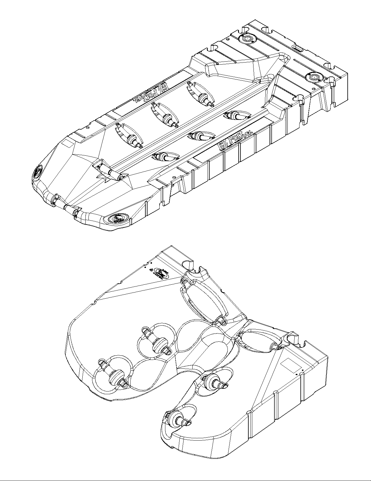
The EZ Port MAX must oat freely on the water surface, moving up and down with any changes in water level. To
accomplish this there are a number of anchoring/installation methods available for use with the EZ Port MAX.
Site Conditions to be Considered
Every EZ Port MAX installation will be site specic and must be congured specically for the end user’s intended
application. Some factors that must be taken into consideration when determining the components necessary for a
proper installation are: intended usage, water conditions, soil/bed conditions, and climatic conditions. There are a few
simple rules to follow when determining layout conguration.
Be certain that your installation conguration is designed to accommodate the daily intended use of your EZ Port MAX.
Please take into account the following:
Commercial application needs•
Public access requirements•
Private docking needs•
Scale of operation and use (size of PWCs, number of people, etc.)•
Other special considerations affecting your daily use•
Be aware of the unique characteristics of the specic body of water and consider how such conditions will affect the
installation. Take into account:
Overall area of the body of water•
Water depth (at the shore and at the furthest point from shore)•
Normal and greatest wave action•
Water level uctuation•
Fresh, brackish, or salt-water•
Normal ice thickness and movement•
Lakebed and soil conditions (sand, rock, mud, etc.)•
Usage
Understand and consider installation/performance requirements then evaluate your ability to fulll them.
Determine whether your installation will be attended and inspected on a regular basis.•
Become acquainted with the normal movement associated with oating structures.•
Determine whether you are capable of performing your own installation, or whether it is best to hire a•
professional.
Once you have considered and worked out the issues above, the next step is to select the installation mounting
method that is best for you. Since no two installations are ever exactly the same, each and every EZ Port MAX
installation must be designed and congured for the specic and intended application.
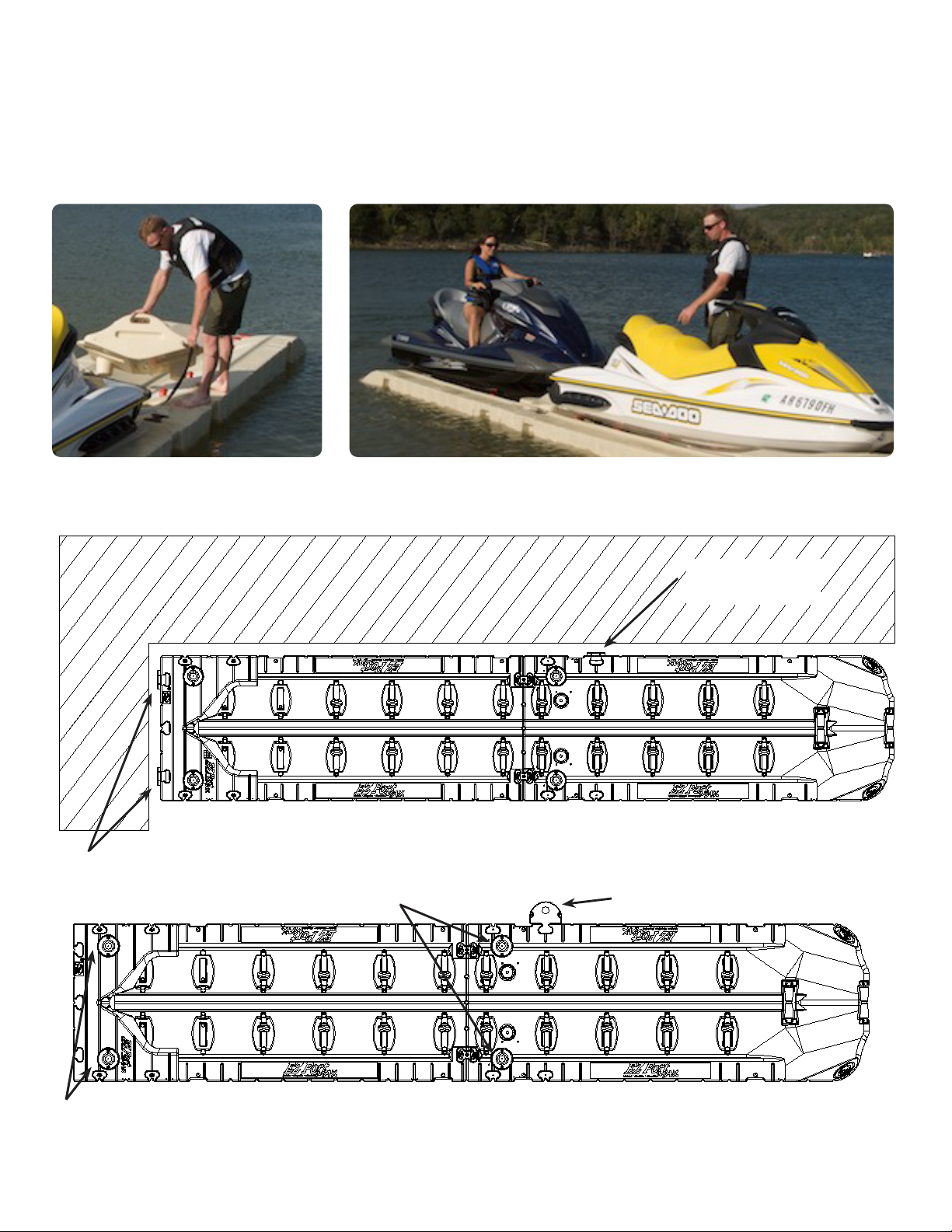
Installation with an EZ Dock System (Section 3.):• When installing the EZ Port MAX on an EZ Dock system,
simply use standard EZ Dock coupler sets to connect the EZ Port MAX to the EZ Dock. (refer to the installation
instruction section 3).
Installation with Pipes (Section 4.):• Anchoring the EZ Port MAX with pipes allows for stand alone installations.
The integrated pipe brackets are utilized for these installations (refer to the installation instruction section 4 for
stationary/xed piers , docks bulkheads, seawalls, etc.).
Installation with other oating dock systems (Section 5. & 6.):• The EZ Port MAX can be attached to other
oating docks with the oating dock adapter hinge kit (refer to the installation instruction section 5 for when Small
Bow Section is used and 6 for Full Bow Section).

For more information call 1-800-654-8168 or go to www.ez-dock.com.
8
Assembly of Bow Sections onto EZ Port MAX
There are two bow sections for the EZ Port MAX. These bow sections protect the PWC from going too far forward during
loading and provide for PWC tie down. A bow section must be installed before installation and use of the EZ Port MAX for
single/tandom PWC EZ Port MAX applications (using just the entry section 206030PW-**):
- The half bow section (206027BS-**) is an economical way to protect your PWC, (Figure 1). To install, the half bow
section is inserted into the holes located near the front of the entry section. Push the half bow section down rmly into the
holes and install two (2) bolts (Item 4). When the half bow section is fastened in this way, it will not require Item 2 or Item
3, (Figure 1).
- The full bow section (206025BS-**) must be used to attach the EZ Port MAX to new or existing EZ Dock oating docks
and provides additional walking surface, (Figure 2). To install, place the full bow section onto the front of the entry section
and align the front with the front of the entry. Install four (4) bolts and washers (Items 9 & 10) into the holes as indicated
below and tighten.
- For in-line EZ Port MAX applications - Please refer to page 16.
Warning: A bow section must always be used!
Tools required:
Phillips Screwdriver•
Ratchet and socket set or open-end, boxed-end wrench set•
Open-end, boxed-end wrench set•
BILL OF MATERIAL
ITEM QTY. PART NO. DESCRIPTION
1 1 206030PW-** EZ Port MAX Entry
2 2 80575SS Bolt 5/16”-18 x 3/4” Truss HD 18-8 SS
3 1 S22025 Tether Cord, 36” x 1” Nylon F/ Port MAX
4 2 80524SS Bolt 5/16”-18 X 2 1/4” Truss HD 18-8 SS
5 1 S26027-** Bow Section, Half F/ Port MAX
6 1 S26025BS-** Bow Section, Full F/ Port MAX
7 2 S20616** Cover, Pipe Bracket Sleeve
8 4 80514SS Bolt 5/16”-18 x 1 1/4” Truss HD 18-8 SS
94 80545SS Bolt 5/16”-18 x 4 1/2” HD 18-8 SS
10 4 117005 Washer 3/8” x 1” O.D. Flat 18-8 SS
Figure 1. Figure 2.
1
2
3
4
5
10
6
9
7
8

For more information call 1-800-654-8168 or go to www.ez-dock.com. 9
Step 2: Roller Relocation - The EZ Port MAX Extension is shipped with twelve (12) rollers (250023-OR). Four (4) rollers at
the front of the extension must be removed and reinstalled at the front of the EZ Port MAX entry section (Figure 4). The rollers
are easily pried out of their locations with the help of a large screw driver or pry bar. Pry out the end of the roller shaft that is
on the high side of the port. After the shaft pops out of the high side pocket, the roller shaft may be slid out of the lower shaft
pocket. Move these four (4) rollers to the front of the EZ Port MAX entry section, (Figure 4). To re-install the rollers, slide the
roller shaft into the lower shaft pocket. Then, with the roller shaft aligned over the top shaft pocket, drive it into place by a rm
blow with a rubber mallet or dead-blow hammer.
BILL OF MATERIAL
ITEM QTY. PART NO. DESCRIPTION
1 1 206030PW-** EZ Port MAX Entry
2 1 206031PW-** EZ Port MAX Extension
3 16 250023-OR Kit, Injection Roller Orange for Port MAX
4 2 301208 Kit, Coupler Set (2) Pair, Port to Port
Figue 4. 1
3
2
Rollers should turn freely. If
necessary use a marine safe
lubricant between shaft and
roller to aid rotation.
Detailed View A
Figue 3.
4
3
1
2
1. In-line Conguration
Step 1: Assembly - Align the EZ Port MAX Entry section (206030PW-**) with the EZ Port MAX Extension
(206031PW-**) and install two (2) coupler sets provided in the Port to Port Coupler Kit (301208).
Tools required:
Tool, Composite Coupler Installation (900005)•
EZ Dock in-water installation tool (900010)•
Hammer (rubber mallet or dead blow)•
Screwdrivers (Phillips and standard)•
Pry-bar (small and large)•
Ratchet and socket set•
15/16” or 24mm socket•

For more information call 1-800-654-8168 or go to www.ez-dock.com.
10
Step 3: Assemble a Full Bow Section at the front of the EZ Port MAX Extension. (See page 8, Figure 2 for Full Bow Section
assembly instructions).
Step 4: The half bow section (206025BS-xx) is required for use between PWC’s. The half bow section is assembled at
the front of the entry section as a removable stop between the PWC’s (refer to Page 8, Figure 1). The half bow section is
tethered using a nylon tether (Item 3) and two (2) bolts (Item 2). When used on an in-line port application Item 2 and Item 3
are required and the four (4) bolts (Item 4) are omitted.
Step 5: Installation - For Installation/Attachment of the assembled in-line EZ Port MAX Entry + Extension please see below
and refer to the Installation/Attachment Section, pages 8 - 18.
Hinge kit (see Section 5, 6) used to anchor to a oating dock. Add hinge kit to entry section if additional stability is required.
Additional hinge, 100751
or 100751SS if required.
Floating Dock
When anchoring the Port MAX in the in-line conguration with pipe (Section 1.), only use the integrated pipe bracket locations at
the front of the EZ Port Extension. If additional stability is required, a pipe bracket(s) may be added to the outside of the entry
section.
Do not use pipe here with in-line conguration. Additional pipe bracket (s), 130251 on ouside of port.

For more information call 1-800-654-8168 or go to www.ez-dock.com. 11
2. Assembly of EZ Port MAX Easy-Lift Entry - 206033EX-**
Align the EZ Port MAX Easy-Lift Entry (206033EX-**) to an EZ Dock Port MAX Extension (206031PW-**) and couple
together using two (2) EZ Dock Port to Port Coupler Kits (301208).
NOTE: The EZ Port MAX Extension and EZ Port MAX Easy-Lift Entry must be sitting level on the water and at the same
elevation for the coupler to properly seat into the bottom pocket. This may require a counter balance weight toward the entry
end of the EZ Port MAX Easy-Lift Entry to offset the weight of the installer who is standing at the seam between the EZ Port
MAX Extension and the EZ Port MAX Easy-Lift Entry.
Warning: No walking surface on angled surface of EZ Port MAX Entry Extension!
Tools required:
EZ Dock In-Water Installation Tool (900010)•
Ratchet and socket set•
Composite Coupler Installation Tool (900005)•
Screwdrivers (Phillips and standard)•
15/16” or 24mm socket•
Pry-bar (small and large)•
Hammer•
BILL OF MATERIAL
ITEM QTY. PART NO. DESCRIPTION
1 1 206031PW-** EZ Port MAX Extension
2 2 301208 Port to Port Coupler Set
3 1 206033EX-** EZ Port MAX Easy-Lift Entry
4 1 206025BS-** Bow Section Full for EZ Port MAX
Detailed View B
Figure 5.
2
4
1
3
NOTE: Testing has also shown that some watercrafts and user preference resulted to water ballasting the
entry (206033EX-**) with water (see EZ Launch Owners Manual). This is done by simply lling the entry
with water to the desire level. This allows the watercraft an easier entry and even a more stable platform.

For more information call 1-800-654-8168 or go to www.ez-dock.com.
12
BILL OF MATERIAL
ITEM QTY. PART NO. DESCRIPTION
1 1 206030PW-** EZ Port MAX Entry
2 3 301100 Coupler Set
3 1 9000010 In-Water Installation Tool
4 1 208010 80” x 10’ Dock Section
5 1 206025BS-** Bow Section Full for EZ Port MAX
Figure 6.
1
2
3
5
4
3. EZ Dock System Installation
The EZ Port MAX mounts to existing or new EZ Dock installations using standard EZ Dock couplers. In order to attach
the EZ Port MAX to an EZ Dock system, the Full Bow section (206025BS-**) MUST be used, (Figure 6) or use the EZ Port
MAX Integrated Bow Section (206032PW-**).
Tools required:
EZ Dock In-Water Installation Tool (900010)•
Ratchet and socket set•
Composite Coupler Installation Tool (900005)•
Screwdrivers (Phillips and standard)•
15/16” or 24mm socket•
Pry-bar (small and large)•
Hammer•

For more information call 1-800-654-8168 or go to www.ez-dock.com. 13
BILL OF MATERIAL
ITEM QTY. PART NO. DESCRIPTION
1 1 15/16” Socket
2 3 22003 EZ Dock Coupler Nut
3 1 Ratchet
4 6 311010 Coupler
5 1 900005 Composite Coupler Installation Tool
6 1 9000010 In-Water Installation Tool
Figure 10.
3
4
6
5
2
1
Figure 9.
Indicator Hole
Coupler Installation for EZ Dock Attachment
Insert the composite coupler bolt into coupler. Align the index mark on the
head of the bolt so that the splines line up into the notched pockets in the
coupler. Using a hammer to seat the bolt into the coupler, (Figure 7).
Install coupler with seated bolt on the in-water installation tool, (Figure 8).
Align dock sections so coupler pockets are adjacent to each other (Figure 6).
Next, using the in-water installation tool insert the coupler and bolt assembly
into the bottom pocket with the bolt pointing upward, (Figure 6). Pull up on
the in-water installation tool to seat the bottom coupler. (NOTE: The EZ
Dock and EZ Port MAX must be setting level on the water and at the same
elevation for the coupler to properly seat into the bottom pocket. This may
require a counter balance weight toward the entry end of the EZ Port MAX
to offset the weight of the installer who is standing at the seam between the
EZ Port MAX and the EZ Dock). The coupler is fully seated in its pocket
when the indicator hole on the in-water installation tool (Figure 9) is ush with
the top of the dock (you should be able to insert a screwdriver through the
indicator hole). While holding pressure, insert the top coupler into the opposing
pocket by aligning the hole in the top coupler over the rod and pushing the coupler into the pocket, (Figure 9).
Install the coupler nut onto the bolt and tighten until the top of the bolt is 3/8 -1/2” below the top of the nut (do not torque
over 15 ft-lb). Due to the security feature on the coupler nut, the coupler installation tool is required for tightening. The
coupler installation tool is splined on the end to be inserted into the coupler nut and the other end is a 15/16” bolt. This is
inserted into a 15/16” socket with ratchet for tightening (Figure 10).
DO NOT OVER TIGHTEN THE COUPLER NUT! (Do not torque over 15 ft-lb)
Figure 7.
Figure 8.

For more information call 1-800-654-8168 or go to www.ez-dock.com.
14
4. Installation of EZ Port MAX with Integrated Pipe Brackets (Stand-alone Installation)
When using pipes to secure your new EZ Port MAX, they must be sufciently embedded (driven or augered) into the lake-,
river, or ocean-bed to a minimum depth of 1/3 the water depth. The actual embedment required will vary depending on the
bottom soil conditions.
Your EZ Port MAX Port comes equipped with pipe mounting holes. These holes are capped when not in use (see Detailed
View C) and act as wear sleeves. A hole must be created in the center of the cap to accommodate the pipe and pipe wear
sleeve, (Figure 13).
The EZ Port MAX (shown below in Figure 11) is designed to use 3.0” schedule 40 galvanized pipe with an outside diameter
of 3.5” sleeved with 4.0” schedule 40 PVC pipe to act as a wear sleeve.
Tools required:
Drill•
1/2” drill bit•
Large pipe wrench•
Ratchet and socket set•
Screwdrivers (Phillips and standard)•
3/4” or 19mm socket•
3/4” or 19mm wrench•
Hole saw•
Utility knife•
Post level•
Hammer•
Tape Measure•
BILL OF MATERIAL
ITEM QTY. PART NO. DESCRIPTION
1 1 206030PW-** EZ Port MAX Entry
2 2 3” Schedule 40 Galvanized Pipe
3 2 10355 Auger Kit 3.5”
4 2 80124 Bolt 1/2”-13 x 4” Hex. HD GRD 5 ZP
5 2 80119YZ Nut 1/2” Hex. YZ
6 2 S20614** Pipe Bracket Sleeve Cover
7 4 80514SS Bolt 5/16”-18 1 1/4” Truss HD 18-8 SS
8 2 4” PVC Pipe
Figure 11.
Detailed View D
Detailed View C
1
3
5
4
2
8
6
7

For more information call 1-800-654-8168 or go to www.ez-dock.com. 15
For ease of installation, it is recommended to use pipe augers, except in rocky or shale bottoms. Augers allow the pipe to
be turned into the lake, river, or ocean-bed like a cork screw by using a pipe wrench, or by drilling a hole in the pipe and
using a T-handle, (Figure 14). If a hole is drilled in the pipe, (Figure 14) then the hole must be removed by cutting the top of
the pipe below the hole or installing a PVC sleeve over the pipe, (Figure 11).
Tools required:
Drill•
Drill bit•
Ratchet•
3/4” or 19mm socket•
3/4” or 19mm wrench•
Cut here for 3 1/2”
pipe sleeved with
4” PVC pipe.
Figure 12.
Figure 13.
Remove the pipe caps (Figure 12) and cut 4 1/2” holes in them (holes can be drilled with 4 1/2” hole saw (Figure 13), cut
with a utility knife, or other plastic cutting tool). Re-install the caps on the EZ Port MAX.
Locate the EZ Port MAX where you want it to be installed and insert the 3 1/2” galvanized pipes through the pipe holes.
Install the pipe by sufciently embedding it into the bottom by either driving/pounding or augering (See gure 14 below).
Be sure to keep the pipe plumb so that the EZ Port MAX will oat freely.
The 4” PVC sleeve is installed by sliding the 4” PVC pipes over the 3 1/2” galvanized pipes.
(A more nished look can be obtained by putting a PVC cap on the top)
BILL OF MATERIAL
ITEM QTY. PART NO. DESCRIPTION
1 1 100355 Kit Auger for 3 1/2” Pipe
2 1 T Handle
3 1 3” Schedule 40 Galvanized Pipe
2
3
1
Figure 14.

For more information call 1-800-654-8168 or go to www.ez-dock.com.
16
5. Installation of EZ Port MAX with Small Bow Section to a Floating Dock using Hinge Kit
100751 & 100751SS
The 100751 or 100751SS hinge kit is required when anchoring an EZ Port MAX (206030PW-**) with half bow section
(206027BS-**). The half bow section should be attached to the EZ Port MAX with the screws provided prior to installation,
(See Page 7 Figure 1 for bow section installation instructions).
Measure the freeboard of the fascia of the oating dock where the connection will be made.1.
Determine the best position for the hinge adapter plate. The plate can be above (Figure 15), perpendicular (Figure2.
17), or directly in front of the hinge adapter bracket, (Figure 16).
No additional weight should be on the port while measuring hinge adapter plate location.3.
When attaching to a wooden structure, use carriage bolts (not included) to attach the adapter plate. If attaching to a4.
steel or aluminum structure, it may be necessary to rst attach a 2” X 8” (5cm X 20cm) wooden fascia (not included).
When attaching to a concrete oating dock, concrete anchor bolts (not included) may be required.5.
When the adapter hinge plate is securely in place, oat the EZ Port MAX into position and secure the hinge pins.6.
Tools required:
Drill•
Drill bits•
Ratchet and socket set•
Screwdrivers (Phillips and standard)•
Open-end, boxed-end wrench set•
15/16” or 24mm socket•
Pry-bar (small and large)•
Tape measure•
Hammer•
Pliers•
BILL OF MATERIAL
ITEM QTY. PART NO. DESCRIPTION
1 1 206030PW-** EZ Port MAX Entry
2 2 S21140SS Connector Hardware w/ SS
3 2 S10751GV Floating Dock Adapter, Hinge to Port MAX
4 2 S80968SS Hinge Pin SS for Floating Dock Adapter
5 2 S10712GV Hinge Dock Apater Plate - Hot Dip Galv.
6 2 80580SS Nut 5/8”-11 Self Locking 18-8 SS
7 2 80011 Clip Hitch Pin #11, EZ Dock
8 1 206027BS-** Bow Section, Half F/ Port MAX
Figure 15.
1
2
7
6
34
5
8

For more information call 1-800-654-8168 or go to www.ez-dock.com. 17
The hinge dock adapter plate, (Item 5), may be installed with the hinge point on the top as shown, (Figure 16). All other
installation is the same as on previous page.
Tools required:
Drill•
Drill bits•
Ratchet and socket set•
Screwdrivers (Phillips and standard)•
15/16” or 24mm socket•
Pry-bar (small and large)•
Hammer•
Pliers•
Tape measure•
Open-end, boxed-end wrench set•
BILL OF MATERIAL
ITEM QTY. PART NO. DESCRIPTION
1 1 206030PW-** EZ Port MAX Entry
2 2 S21140SS Connector Hardware w/ SS
3 2 S10751GV Floating Dock Adapter, Hinge to Port MAX
4 2 S80968SS Hinge Pin SS for Floating Dock Adapter
5 2 S10712GV Hinge Dock Apater Plate - Hot Dip Galv.
6 2 80580SS Nut 5/8”-11 Self Locking 18-8 SS
7 2 80011 Clip Hitch Pin #11, EZ Dock
8 1 206027BS-** Bow Section, Half F/ Port MAX
Figure 16. 1
3
5
2
7
6
4
8

For more information call 1-800-654-8168 or go to www.ez-dock.com.
18
6. Installation of EZ Port MAX with Full Bow Section to a Floating Dock using Hinge Kit 100750
& 100750SS
The 100750 or 100750SS hinge kit is required when anchoring a EZ Port MAX Entry (206030PW-**) with Full Bow
Section (206025BS-**), (Figure 17) or the EZ Port MAX Integrated Bow (206032PW-**). The full bow section must be
attached to the EZ Port MAX with the screws provided prior to the installation, (See Page 8 Figue 2 for bow section
installation instructions).
Measure the freeboard of the fascia of the oating dock where the connection will be made.1.
Determine the best position for the hinge adapter plate. The plate can be above (Figure 15), perpendicular (Figure2.
16), or directly in front of the hinge adapter bracket, (Figure 17).
No additional weight should be on the port while measuring hinge adapter plate location.3.
When attaching to a wooden structure, use carriage bolts (not included) to attach the adapter plate. If attaching to a4.
steel or aluminum structure, it maybe necessary to rst attach a 2” X 8” (5cm X 20cm) wooden fascia (not included).
When attaching to a concrete oating dock, concrete anchor bolts (not included) may be required.5.
When the adapter hinge plate is securely in place, oat the EZ Port MAX into position and secure the hinge pins.6.
Tools required:
Drill•
Drill bits•
Ratchet and socket set•
Screwdrivers (Phillips and standard)•
Open-end, boxed-end wrench set•
15/16” or 24mm socket•
Pry-bar (small and large)•
Tape measure•
Hammer•
Pliers•
BILL OF MATERIAL
ITEM QTY. PART NO. DESCRIPTION
1 1 206030PW-** EZ Port MAX Entry
2 1 206025BS-** Bow Section Full Port MAX
3 2 S21140SS Connector Hardware w/ SS
4 2 S10713GV Floating Dock Adapter, Hinge to Float Galv
5 2 S80968SS Hinge Pin SS for Floating Dock Adapter
6 2 S10712GV Hinge Dock Apater Plate - Hot Dip Galv.
7 2 80580SS Nut 5/8”-11 Self Locking 18-8 SS
8 2 80011 Clip Hitch Pin #11, EZ Dock
6
3
Figure 17.
5
2
1
4
8
7

For more information call 1-800-654-8168 or go to www.ez-dock.com. 19
Porting Instructions
#1 Idle Up to the EZ Port MAX entry
Idle the nose of the watercraft to the stern roller of the EZ Port
MAX entry. Come to a complete stop and allow the watercraft to
center itself with the keel in-line with the center of the rollers.
IT IS NOT RECOMMENDED OR NECESSARY TO BUILD UP
MOMENTUM TO DOCK ON THE EZ PORT MAX.
#2 Ease into the Throttle
Once the watercraft is in-line with the rollers, simply ease into
the throttle and allow the machine to roll forward into the proper
position.
There is a learning curve with this technique and it may take you
several attempts to get the watercraft into the proper position.
#3 Roll Aboard
When docking is complete, your watercraft should be all the way
out of the water and stable on the port. The watercraft should be
secured to the port when not in use.
The EZ Port MAX is a simple drive-on, push-off method of dry docking your PWC. The self oating EZ Port MAX moves
with the changing water levels and protects your watercraft from wind, wave, or other environmental conditions. The EZ
Port MAX comes from the factory with an adjustable roller in its recommended position. However, you still may need to
make minor roller adjustments. It is very important to ensure that the watercraft enters the port and disembarks with the
weight distributed on the rollers and not rubbing on the polyethylene port walls. The roller should be adjusted accordingly
to get optimum results. Launching your watercraft should also be effortless and one person should be able to shove the
watercraft back into the water. If your watercraft is difcult to launch, seek help and contact your local dealer for roller
set-up. Do not try to launch a “stuck” PWC by yourself.

For more information call 1-800-654-8168 or go to www.ez-dock.com.
20
Keel Roller Adjustment for EZ Port MAX
The EZ Port MAX comes from the factory with one adjustable roller. The roller is factory installed in Position 2. It may be
necessary to adjust the roller on your new EZ Port MAX. Your EZ Port MAX can be adjusted to t most personal watercraft
(PWC). The roller can be placed in any one of four positions. The illustrations below show each of the four positions. A
roller placed too high or too low may cause difculty in docking and launching your PWC. This process may take several
adjustments before getting the correct position for your PWC model. Your EZ Port MAX is designed to make launching and
docking fast, fun, and easy.
Position 1
A. Axle plate up.
B. Spacers above plate.
Position 2 (Default)
A. Axle plate up.
B. Spacers below plate.
Position 3
A. Axle plate down.
B. Spacers above plate.
Position 4
A. Axle plate down.
B. Spacers below plate.
Tools required:
Phillips Screwdriver•
Procedure:
Loosen 4 screws, (Item 3), and remove.
For Position 1, remove roller (Item 4) and spacers (Item 2).
Replace roller as shown in illustration above. Place
spacers on top of axle plate as shown. Install screws and
tighten.
For Position 3, remove roller (Item 4) and spacers (Item 2).
Replace roller as shown in illustration above. Place
spacers on top of axle plate as shown. Install screws and
tighten.
For Position 4, remove roller (Item 4). Replace roller as
shown in illustration above with spacers (Item 2) below
plate. Install screws and tighten.
BILL OF MATERIAL
ITEM QTY. PART NO. DESCRIPTION
1 4 80575SS Bolt 5/16”-18 x 3/4” Truss HD 18-8 SS
2 4 S32050 Spacer 1” OD x 3/8” ID Black Polyethylene
3 4 80514SS Bolt 5/16”-18 x 1 1/4” Truss HD 18-8 SS
4 2 M25012 Keel Roller Assembly 12”
3
1
4
2
This manual suits for next models
6
Table of contents
Other EZ Dock Boating Equipment manuals
Popular Boating Equipment manuals by other brands

Reverso
Reverso Outboard Flushing System 1.5 manual

Scanstrut
Scanstrut Scanpod SPR-7-AM installation instructions

Yakima
Yakima EasyRider owner's manual

Selden
Selden Furlex 300 H Assembly and operational manual

Superfly
Superfly SQC Setup guide

Taco Marine
Taco Marine NEPTUNE PREMIUM Installation instruction guide