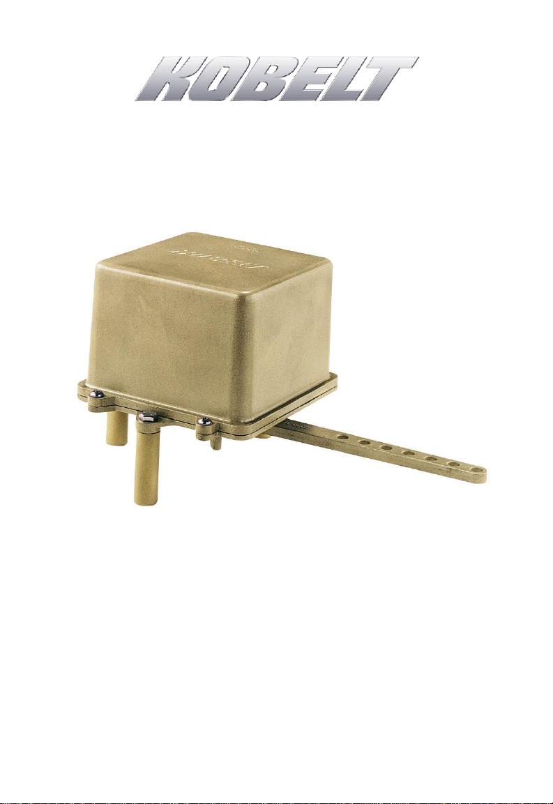
7174 Rudder Feedback Unit Kobelt Manufacturing Co. Ltd.
Rev A mnl7174.docx 3 of 21
TABLE OF CONTENTS
1Introduction .......................................................................................................... 4
1.1 Contact .......................................................................................................................4
1.2 Compliant Use ............................................................................................................4
1.3 Copyrights & Trademarks...........................................................................................4
2Safety.................................................................................................................... 5
2.1 Safety Alerts ...............................................................................................................5
2.2 Notice to Installer.......................................................................................................5
2.3 Product Hazards .........................................................................................................6
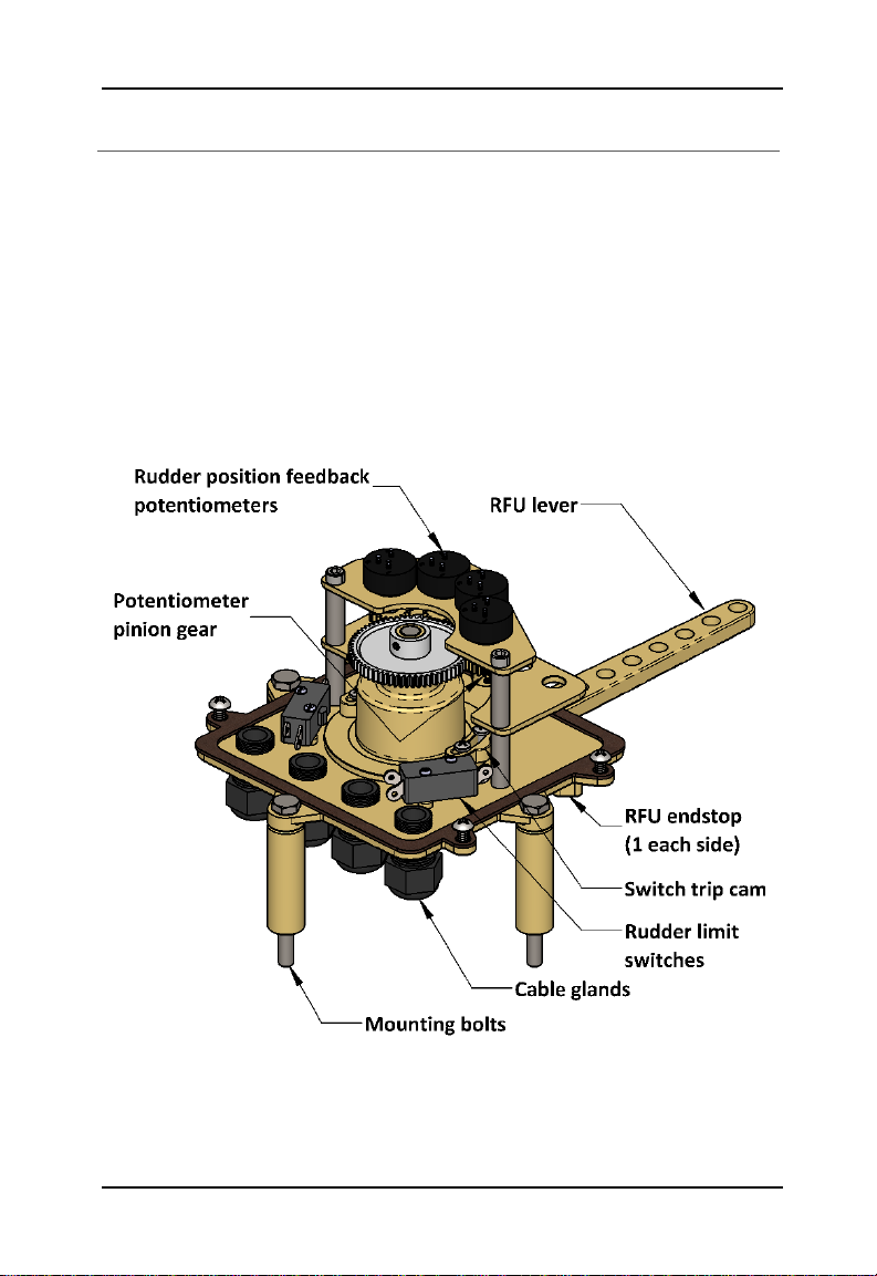
3Product Description ............................................................................................... 7
3.1 Technical Specifications .............................................................................................8
3.2 Model Code Key .........................................................................................................8
4Installation............................................................................................................ 9
4.1 Mechanical .................................................................................................................9
4.2 Electrical ...................................................................................................................10
5Commissioning.................................................................................................... 13
5.1 Electrical Check.........................................................................................................13
6Maintenance ....................................................................................................... 14
6.1 Preventative Maintenance.......................................................................................14
6.2 Service ......................................................................................................................14
6.3 Recommended Spare Parts......................................................................................15
7Troubleshooting .................................................................................................. 16
8Warranty............................................................................................................. 17
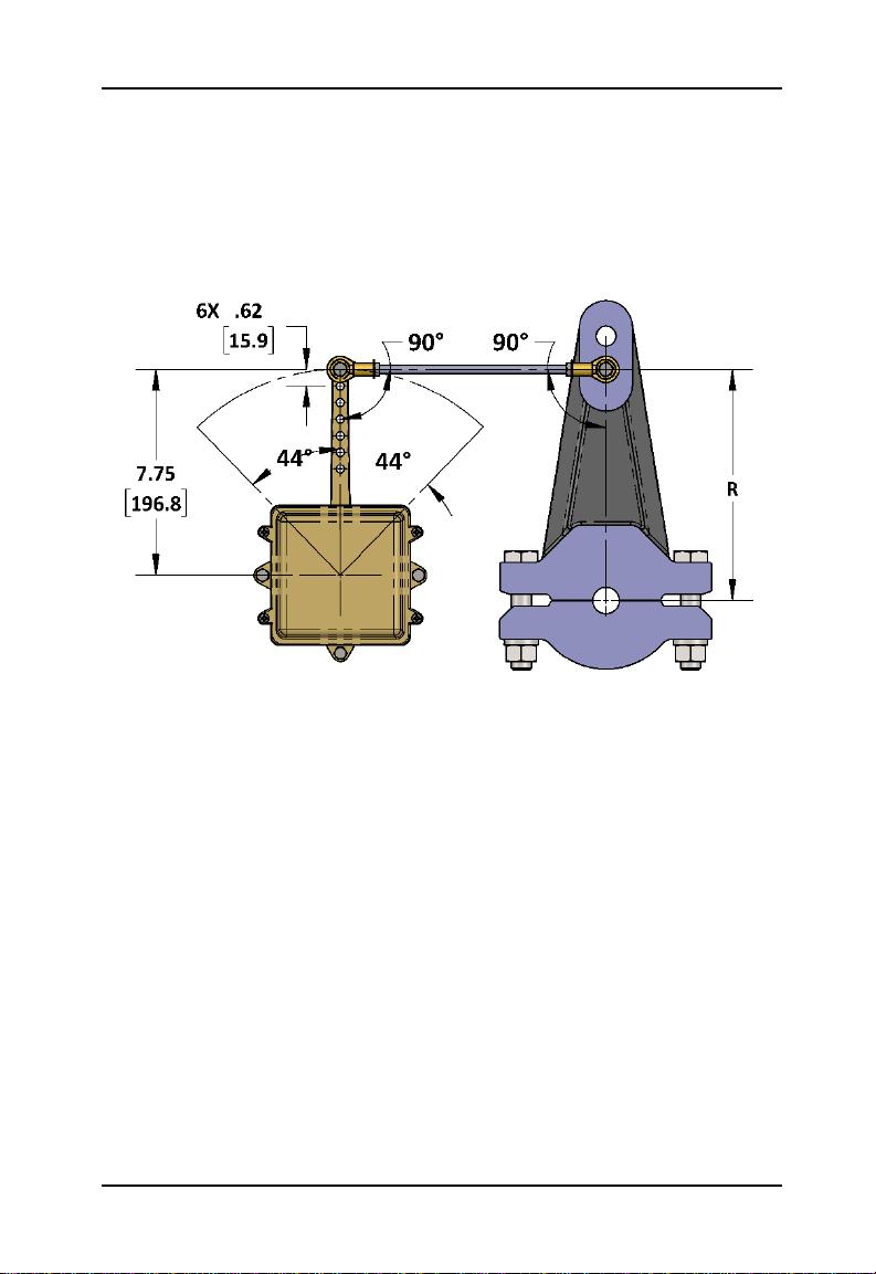
9Appendix A: Installation Dimensions .................................................................... 18
10 Appendix B: Parts List .......................................................................................... 19