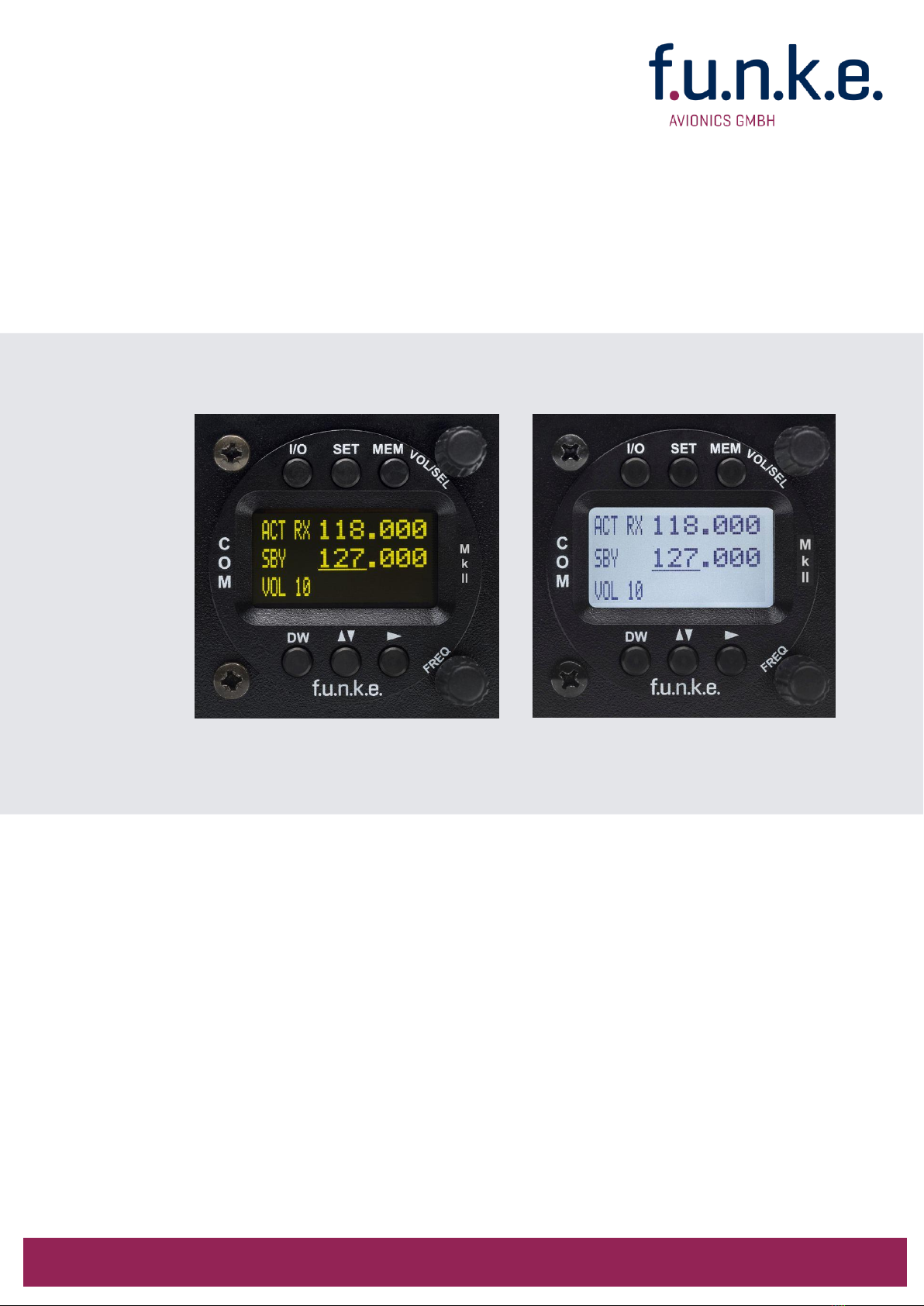
ATR833-II / P/N 833-II (Cxxx)-(Cxxx)
Operation and Installation
3 Doc.-No. 01.143.010.71e / Revision 1.01
CONTENT
1
GENERAL .......................................................................................................................................... 5
1.1
S
YMBOLS
.................................................................................................................................................... 5
1.2
A
BBREVIATIONS
........................................................................................................................................... 5
1.3
C
USTOMER
S
UPPORT
.................................................................................................................................... 6
1.4
E
QUIPMENT
C
HARACTERISTICS
........................................................................................................................ 6
2
OPERATION ...................................................................................................................................... 7
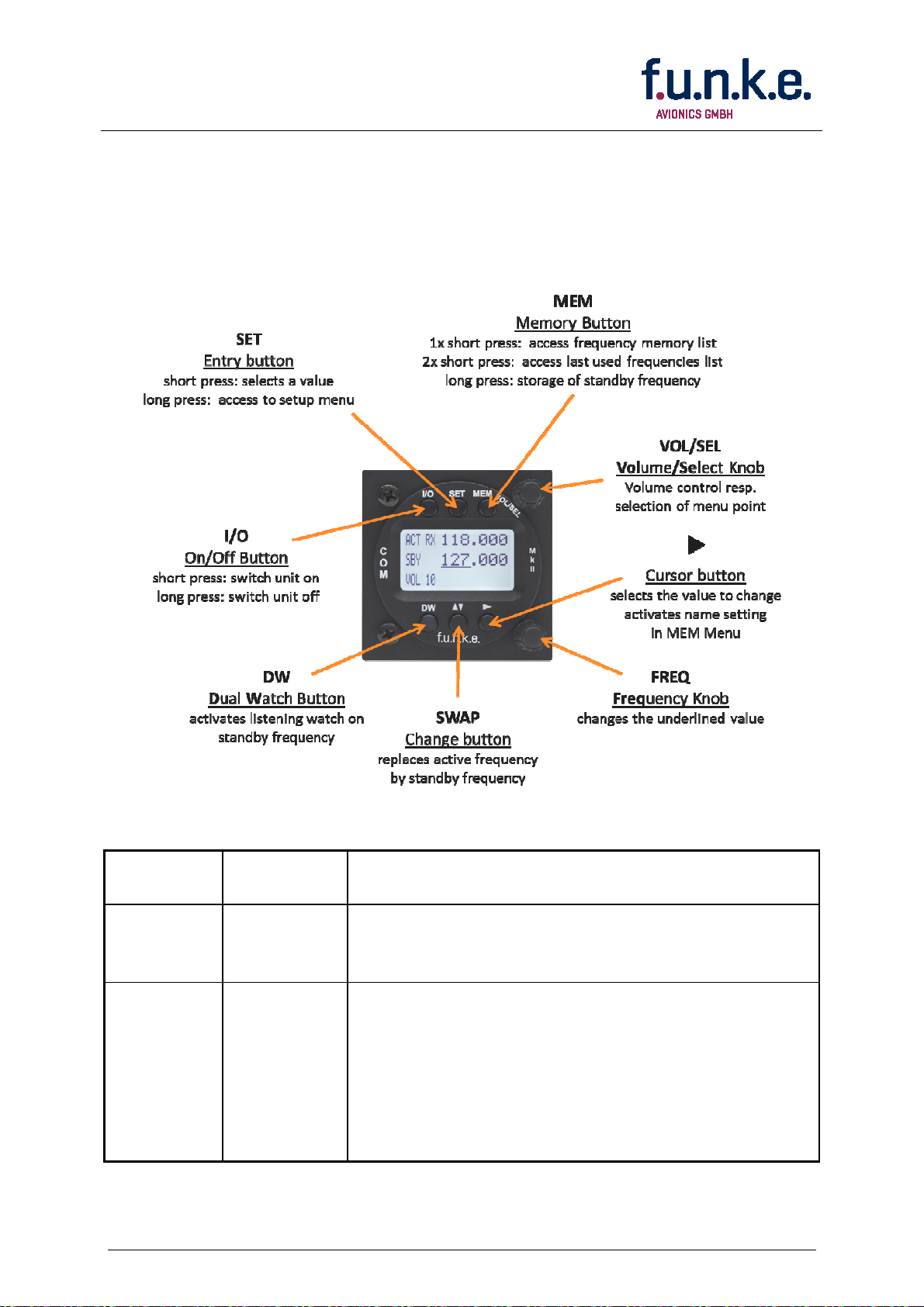
2.1
O
VERVIEW OF
C
ONTROLS
............................................................................................................................... 7
2.2
ON/OFF
-
C
OMMISSIONIN
.......................................................................................................................... 8
2.3
D
ISPLAY
...................................................................................................................................................... 9
2.4
F
REQUENCY
S
ETTIN
................................................................................................................................... 11
2.4.1
Automatic Selection 8.33 / 25 kHz Channel Bandwidth ........................................................................ 11
2.4.2
Manual F equency Input ....................................................................................................................... 11
2.4.3
Recall a F equency f om the Use Memo y ........................................................................................... 12
2.4.4
Recall a F equency f om the List of the 10 Last Used ............................................................................ 13
2.4.5
Sto age of a F equency into the Use Memo y ..................................................................................... 14
2.4.6
ATR F equency Tool ............................................................................................................................... 15
2.5
B
ASIC
S
ETTIN S
......................................................................................................................................... 16
2.5.1
VOL – Volume ........................................................................................................................................ 16
2.5.2
SQL – Squelch (noise ba ie ) ................................................................................................................. 17
2.5.3
VOX –Voice Activated Inte com ............................................................................................................ 17
2.5.4
INT – Volume Inte com .......................................................................................................................... 18
2.5.5
STL – Volume Sidetone Left ................................................................................................................... 18
2.5.6
STR – Volume Sidetone Right ................................................................................................................ 19
2.5.7
EXT – Volume of the exte nal Audio Input............................................................................................. 19
2.5.8
BRT – B ightness .................................................................................................................................... 20
2.5.9
CON – Cont ast ...................................................................................................................................... 20
2.6
T
RANSMISSION
.......................................................................................................................................... 21
2.7
R
ECEPTION
................................................................................................................................................ 21
2.8
REPLAY
F
UNKTION
.................................................................................................................................... 22
2.9
DUAL
WATCH
O
PERATION
........................................................................................................................ 22
3
CONFIGURATION ........................................................................................................................... 24
3.1
SPACIN
–
C
HANNEL
S
PACIN
................................................................................................................... 24
3.2
DISPLAY
–
E
NER Y
S
AVIN
M
ODE
(A
UTOMATIC
D
ISPLAY
D
ARKENIN
).............................................................. 25
3.3
PTT
SELECT
-
B
UTTON
S
ELECTION
............................................................................................................... 26
3.4
DUOWATCH
–
D
UAL
-W
ATCH
V
OLUME
R
EDUCTION
....................................................................................... 28
3.5
EXTAUDIO
–
B
EHAVIOUR OF
E
XTERNAL
A
UDIO
I
NPUT
..................................................................................... 28
3.6
MIC
LEFT
/
RI HT
–
M
ICROPHONE
I
NPUT
S
ENSITIVITY
................................................................................... 30
3.7
MIC
TYPE
–
S
ELECTION
M
IKROPHONE
T
YPE
................................................................................................... 31
3.8
AUTO
ON
–
P
OWER
-U
P
B
EHAVIOR
.............................................................................................................. 31
3.9
FW
/SW
–
F
IRMWARE
/
S
OFTWARE
V
ERSION
................................................................................................. 32
3.10
M
ASTER
R
ESET
–
R
ESET TO
F
ACTORY
S
ETTIN S
................................................................................................ 33
3.11
O
VERVIEW
C
ONFI URATION
M
ENU
(S
ETUP
) ................................................................................................... 34