F.u.n.k.e. ATR833A-II-OLED Instruction Manual

ff.u.n.k.e. f.u.n.k.e. means –fabrication · utilities · network · know-how · engineering
Operation and Installation
(Dokument-Nr. 01.143A.010.71e)
P/N 833-II-(Axxx)-(Axxx)
ATR833A-II-OLED
VHF Communication
Transceiver


ATR833A-II / P/N 833-II (Axxx)-(Axxx)
Operation and Installation
Doc.-No. 01.143A.010.71e / Revision 1.00 2
Change History
Revision
Date
Description of Change
1.00
04.04.2018
First Release Head-SW 1.05 / NF-FW 3.00
List of Service Bulletins (SB)
Service-Bulletins are to be inserted in the manual and to be recorded in
this table
SB Number
Rev. No.
Date of Issue
Entry Date
Name

ATR833A-II / P/N 833-II (Axxx)-(Axxx)
Operation and Installation
3 Doc.-No. 01.143A.010.71e / Revision 1.00
CONTENT
1GENERAL.......................................................................................................................................... 5
1.1 SYMBOLS ....................................................................................................................................................5
1.2 ABBREVIATIONS ...........................................................................................................................................5
1.3 CUSTOMER SUPPORT ....................................................................................................................................6
1.4 EQUIPMENT CHARACTERISTICS........................................................................................................................6
2OPERATION...................................................................................................................................... 7
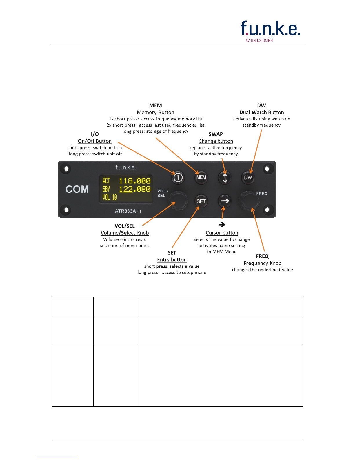
2.1 OVERVIEW OF CONTROLS...............................................................................................................................7
2.2 ON/OFF -COMMISSIONING..........................................................................................................................8
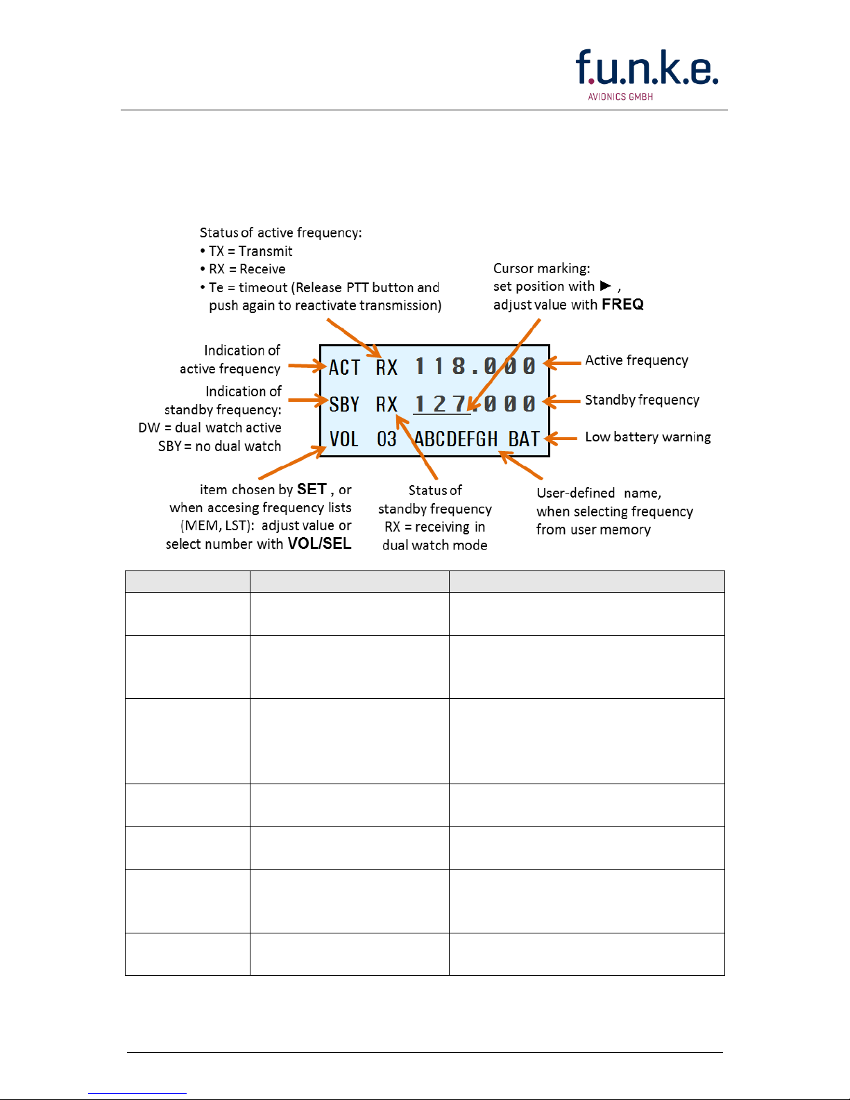
2.3 DISPLAY......................................................................................................................................................9
2.4 FREQUENCY SETTING...................................................................................................................................11
2.4.1 Automatic Selection 8.33 / 25 kHz Channel Bandwidth ........................................................................11
2.4.2 Manual Frequency Input .......................................................................................................................12
2.4.3 Recall a Frequency from the User Memory ...........................................................................................13
2.4.4 Recall a Frequency from the List of the 10 Last Used............................................................................14
2.4.5 Storage of a Frequency into the User Memory .....................................................................................15
2.4.6 ATR Frequency Tool...............................................................................................................................16
2.5 BASIC SETTINGS .........................................................................................................................................17
2.5.1 VOL –Volume........................................................................................................................................17
2.5.2 SQL –Squelch (noise barrier).................................................................................................................18
2.5.3 VOX –Voice Activated Intercom ............................................................................................................18
2.5.4 INT –Volume Intercom..........................................................................................................................19
2.5.5 STL –Volume Sidetone Left ...................................................................................................................19
2.5.6 STR –Volume Sidetone Right ................................................................................................................20
2.5.7 EXT –Volume of the external Audio Input.............................................................................................20
2.5.8 BRT –Brightness....................................................................................................................................21
2.6 TRANSMISSION ..........................................................................................................................................21
2.7 RECEPTION................................................................................................................................................22
2.8 REPLAY FUNKTION....................................................................................................................................22
2.9 DUAL WATCH OPERATION ........................................................................................................................22
3CONFIGURATION ........................................................................................................................... 25
3.1 SPACING –CHANNEL SPACING ...................................................................................................................25
3.2 DISPLAY –ENERGY SAVING MODE (AUTOMATIC DISPLAY DARKENING)..............................................................26
3.3 PTT SELECT -BUTTON SELECTION ...............................................................................................................27
3.4 DUOWATCH –DUAL-WATCH VOLUME REDUCTION.......................................................................................29
3.5 EXTAUDIO –BEHAVIOR OF EXTERNAL AUDIO INPUT .......................................................................................29
3.6 MIC TYPE –SELECTION MICROPHONE TYPE...................................................................................................31
3.7 MIC LEFT /RIGHT –MICROPHONE INPUT SENSITIVITY ...................................................................................31
3.8 HEAD OUT –HEADSET CONFIGURATION.......................................................................................................33
3.9 AUTO ON –POWER-UP BEHAVIOR..............................................................................................................33
3.10 FW /SW –FIRMWARE /SOFTWARE VERSION.................................................................................................34
3.11 MASTER RESET –RESET TO FACTORY SETTINGS................................................................................................35
3.12 ADAPTER OPERATION..................................................................................................................................35
3.13 OVERVIEW CONFIGURATION MENU (SETUP) ...................................................................................................36
4INSTALLATION................................................................................................................................ 37

ATR833A-II / P/N 833-II (Axxx)-(Axxx)
Operation and Installation
Doc.-No. 01.143A.010.71e / Revision 1.00 4
4.1 ADVICE AND TIPS........................................................................................................................................37
4.2 TELECOMMUNICATION DATA........................................................................................................................37
4.3 SCOPE OF DELIVERY ....................................................................................................................................37
4.4 UNPACKING AND INSPECTING THE EQUIPMENT ................................................................................................37
4.5 MOUNTING...............................................................................................................................................38
4.6 EQUIPMENT CONNECTIONS ..........................................................................................................................38
4.6.1 Microphone Connection ........................................................................................................................38
4.6.2 Headset-Connection..............................................................................................................................38
4.6.3 Audio-Input ...........................................................................................................................................39
4.7 WIRING....................................................................................................................................................39
4.7.1 Conductor Cross Section........................................................................................................................39
4.7.2 Connector –Pin Allocation ....................................................................................................................40
4.7.3 Wiring with Cable Harness BSKS833x-S.................................................................................................42
4.8 ANTENNA .................................................................................................................................................43
4.8.1 Antenna Selection .................................................................................................................................43
4.8.2 Installation Recommendation ...............................................................................................................44
4.9 MICROPHONE /INTERCOM SETTINGS .............................................................................................................44
4.10 POST-INSTALLATION CHECK..........................................................................................................................45
4.11 DRAWINGS................................................................................................................................................46
4.11.1 Dimensions ............................................................................................................................................46
4.11.2 Mounting Advices..................................................................................................................................47
5APPENDIX ...................................................................................................................................... 48
5.1 FREQUENCY/CHANNEL-PLAN........................................................................................................................48
5.2 TECHNICAL DATA .......................................................................................................................................49
5.3 ENVIRONMENTAL CONDITIONS......................................................................................................................51

ATR833A-II / P/N 833-II (Axxx)-(Axxx)
Operation and Installation
5 Doc.-No. 01.143A.010.71e / Revision 1.00
1 GENERAL
This manual contains information about the physical, mechanical and
electrical characteristics, as well as information about installation and
operation of the aeronautical VHF voice radio ATR833A-II. The flat panel
radio is only available with OLED display.
1.1 Symbols
Advices whose non-observance can cause radiation damage
to the human body or ignition of combustible materials.
Advices whose non-observance can cause damage to the
device or other parts of the equipment.
Information
1.2 Abbreviations
Abb.
Name / Subject
Definition
BRT
Brightness
Display Brightness
EXT
External Audio Input
Volume of external audio input
INT
Intercom
Volume of board-internal intercom
MIC
Microphone
Sensitivity of Microphone
PTT
Push-To-Talk
Button to activate radio transmission
SEL
Selection
Selection of value or function
SQ
Squelch
Noise suppression radio reception
VOL
Volume
Volume of radio reception
VOX
Voice activation
Volume threshold for voice-activated
intercom

ATR833A-II / P/N 833-II (Axxx)-(Axxx)
Operation and Installation
Doc.-No. 01.143A.010.71e / Revision 1.00 6
1.3 Customer Support
In order to facilitate a rapid return of shipments in case of repairs, please
follow the instructions of the input guide “Reshipment RMA” provided at
the Service-Area within the f.u.n.k.e. AVIONICS GmbH web portal
www.funkeavionics.com.
Any suggestions for improvement of our manuals are
welcome. Contact: service@funkeavionics.com.
Information on software updates is available at f.u.n.k.e.
Avionics GmbH.
1.4 Equipment Characteristics
VHF communication transceiver with 6W output power in 160mm
format
Frequency range 118,000 to 136,975 MHz
2 microphone inputs (auto detection standard or dynamic)
Voice controlled intercom for up to 4 microphones, can be deactivated
for use with an external intercom
Dual-watch technology, simultaneous monitoring of two frequencies
Auxiliary audio input
Memory for 20 user-definable named frequencies
Easy recall of the 10 last used frequencies
High contrast LCD / OLED display 128x64 dot matrix
Wide range power supply 11 –30 VDC
Configurable energy saving mode
To avoid unintentional permanent transmission, the
transmitter automatically stops transmission after 35 seconds
of uninterrupted operation.

ATR833A-II / P/N 833-II (Axxx)-(Axxx)
Operation and Installation
7 Doc.-No. 01.143A.010.71e / Revision 1.00
2 OPERATION
2.1 Overview of Controls
Position and naming of control elements:
The control elements have following functionality:
I/O
ON/OFF
Switch On press button for appr. 0,5 s
Swich Off press button for appr. 3 s
DW
DUAL
WATCH
Activates/deactivates the mode for mutual
reception of standby frequency (display shows
DW instead of SBY)
SET
EINGABE
1.Navigation through the standard menu (VOL,
SQL, VOX, etc.) (adjustment of value with
VOL/SEL, short press of SET for next value
2.Access to setup menu
Press button for min. 5 seconds
3.Navigation through the setup menu (Spacing,
backlight, DW Mute, PTT Select,.)

ATR833A-II / P/N 833-II (Axxx)-(Axxx)
Operation and Installation
Doc.-No. 01.143A.010.71e / Revision 1.00 8
CURSOR
1. Marking (underline) of value for adjustment;
value changeable with FRQ or VOL/SEL
Enter and continue with Cursor Button
short press
2. Activates in MEM menu the entry of names
3. Long press (>2s) activates Replay
SWAP
Changes Active with Standby-Frequency
MEM
Memory
Access to frequency list
(MEM-List) press button shortly once
Access list of 10 last used frequencies
(LST-List) press button shortly twice
Stores Standby frequency to selected memory
(in MEM-List) press button for 2 seconds
VOL/SEL
VOL/SEL
Turn knob
1. Adjust volume or other item selected by SET
(VOL, SQ, VOX, DIM etc.)
2. Select frequency from user memory or list of
last used frequencies
FREQ
FREQ
Turn knob
Change the underlined value (i.e. adjust
standby frequency, or input character when
entering name)
2.2 ON/OFF - Commissioning
Turn the device on with I/O.
Switch On: I/O press for appr. 0.5 seconds
Switch Off: I/O press for appr. 3 seconds
After turning on, following information appears on the display:
ATR833-II
Welcome
The start screen indicates device type and software version. After that
screen the device changes into normal operation (direct input mode).
The radio starts with the same frequencies and settings from before
being switched off.

ATR833A-II / P/N 833-II (Axxx)-(Axxx)
Operation and Installation
9 Doc.-No. 01.143A.010.71e / Revision 1.00
2.3 Display
The ATR833A-II shows the frequencies and the operating condition on a
matrix LCD display with 128 x 64 pixels.
Display
Meaning
Remark
ACT
Fixed label for active
frequency
SBY
Label for standby
frequency, when dual
watch is not activated
Dual watch mode allows
intermittent monitoring of
standby frequency activity
DW
Label for standby
frequency, when dual
watch mode is
activated
Dual watch mode allows
intermittent monitoring of
standby frequency activity
118.000
Active Frequency
Frequency used for trans-
missions and receptions
124.910
Standby frequency
May be monitored in dual watch
mode
RX
Receiving on this
frequency
Usually on active frequen-cy;
can also happen on standby
frequency when DW is activated
TX
Transmitting on active
frequency
PTT pressed

ATR833A-II / P/N 833-II (Axxx)-(Axxx)
Operation and Installation
Doc.-No. 01.143A.010.71e / Revision 1.00 10
Display
Meaning
Remark
Te
Transmission ended
automatically after 35
seconds of continuous
transmission
Release PTT shortly and press
again to re-enable transmission.
VOL 03
Volume level for
receiving
(standard display)
If SEL was pressed, the
appropriate value of the
standard menu are displayed at
this position (see 2.4)
SQL 03
Squelch level
Radio signal strength threshold
required for reception;
suppresses noise and
weak/distant transmitter
DISPLAY on
Timer for backlight
resp. display
brightness
Activates energy saving mode
VOX 05
VOX threshold
Speech level that activates the
intercom
DUOWATCH
-2
Dual Watch Mute
Reduction in volume for dual-
watch-reception on standby
frequency
INT 04
Intercom - Volume
EXT 02
Volume of external
audio signals
Set to 00, if no external device is
connected, to prevent noise
pickup
BRT 07
Brightness of display
CON 05
Contrast of display
only for LCD
MEM 00
Item from user defined
frequency list (20
entries possible)
Substitutes Standby Frequency;
Active frequency can be stored
into this entry with long press on
MEM
LST 00
Item from list of last
used frequencies
Substitutes standby /active
frequency with press of SET /
button.
ABCDEFG
User-defined name in
the frequency list
Displayed while selecting from
user memory, when the user has
assigned a name.
BAT
Very low supply
voltage
Transmission only with reduced
power possible (decreased radio
range!)
≫REPLAY≫
Playback radio call
Replays the last radio call
(max. 9 seconds)

ATR833A-II / P/N 833-II (Axxx)-(Axxx)
Operation and Installation
11 Doc.-No. 01.143A.010.71e / Revision 1.00
2.4 Frequency Setting
Frequency setting is always done by the two steps of
1. Entering a new standby frequency to the desired value, and then
2. Interchanging the new standby frequency and the previous active
frequency by using the swap button
.
.
Entering a new standby frequency can be done by
a) Manual input,
b) Recall of previously stored frequencies from the user memory
(memory locations 1-20), or
c) Recall from the list of the last 10 used frequencies.
2.4.1 Automatic Selection 8.33 / 25 kHz Channel Bandwidth
Whether a frequency is used with channel width 8.33 kHz or 25 kHz, is
automatically determined by the value of the frequency entered, and
requires no additional user activity.
The numbering scheme that is used for distinction of the two channel
widths is internationally standardized by the ICAO, and consistently used
in official documents (like e.g. VFR navigation charts) as well as in the
voice phraseology used by ATC radio communication.
Channels used with 25 kHz width are entered in multiples of 25kHz:
123.500, 123.525, 123.550, 123.575, 123.600 etc. These are compatible
with the old 25 kHz-only radios. To use the same frequencies with
8.33 kHz width, the frequency values entered are increased by 5kHz:
123.505, 123.530, 123.555, 123.580, 123.605 etc.
For more detailed information please refer to chapter 5.1 –but as said
above, for correct channel width selection this knowledge is not required.

ATR833A-II / P/N 833-II (Axxx)-(Axxx)
Operation and Installation
Doc.-No. 01.143A.010.71e / Revision 1.00 12
2.4.2 Manual Frequency Input
The standby frequency is input by
Selecting with the ► button which part of the frequency to change,
and
Changing the selected part with the FREQ rotary knob.
The swap button
interchanges the newly set standby frequency and
the former active frequency.
When having the channel selection configured for 8.33 kHz steps (see
3.1), the frequency is input in three steps:
SBY
118.910
SBY
118.910
SBY
118.910
In order to speed up the entering of new frequencies, it is
possible to configure the radio to allow entering of those
frequencies only that are used with 25 kHz channel width.
Please refer to chapter 3.1 for information on this
configuration.
However, when choosing this option, please keep in mind to
re-enable 8.33 kHz channel selection before flying into areas
where 8.33 kHz channels are used.

ATR833A-II / P/N 833-II (Axxx)-(Axxx)
Operation and Installation
13 Doc.-No. 01.143A.010.71e / Revision 1.00
2.4.3 Recall a Frequency from the User Memory
To access the user memory frequency list, press MEM once, and select
one of the 20 memory entries with the VOL/SEL turn knob.
The selected memory entry is shown instead of the standby frequency.
In the lower row of the display, the number of the memory entry selected
is indicated by [MEM xx] (with xx = 1 to 20); if a name has been
provided by the user for this memory entry, it is displayed next to the
memory entry number.
ACT
123.450
SBY
118.275
MEM
2
Range: 01 - 20
Repectively:
ACT
123.450
SBY
118.275
MEM
2
E
D
N
E
A push on the swap button
replaces the Active Frequency, a press on
the SET button the Standby Frequency with the selected list entry.
If no input is done for 10 seconds, the device returns to the standard
view, too.

ATR833A-II / P/N 833-II (Axxx)-(Axxx)
Operation and Installation
Doc.-No. 01.143A.010.71e / Revision 1.00 14
2.4.4 Recall a Frequency from the List of the 10 Last Used
The radio automatically keeps track of the last 10 used active
frequencies. To access this list, press MEM twice, and select one of the
10 list entries with the VOL/SEL turn knob. The selected memory entry
substitutes the former standby frequency.
The number of the selected list entry is given in the display’s lower row.
ACT
123.450
SBY
118.275
LST
2
Range: 1 - 10
Respectively:
ACT
123.450
SBY
118.275
LST
2
E
D
N
E
8 digits A-Z, 0-9
If there is no input for 10 seconds, the device returns to the standard
view.
List entry “1“ contains the last standby frequency from the
MEM menu.

ATR833A-II / P/N 833-II (Axxx)-(Axxx)
Operation and Installation
15 Doc.-No. 01.143A.010.71e / Revision 1.00
2.4.5 Storage of a Frequency into the User Memory
The active frequency can be stored into any entry of the user memory.
This is achieved by a long press of 1,5 seconds on MEM. The previous
memory entry will be be overwritten.
The following example stores the frequency 124.350 MHz of KONSTANZ
(EDTZ) into the user memory 7:
Step
Display (example)
1. Tune in frequency:
Have frequency to be stored set
as standby frequency
ACT
118.275
SBY
124.350
VOL
05
2. Enter memory list:
With a long press on MEM the
frequency can be stored to the
user memory.
ACT
118.275
SBY
124.350
MEM
saveTo
1
3. Select memory position:
Selection of the decided memory
position with VOL/SEL
ACT
118.275
SBY
124.350
MEM
saveTo
7
4. Overwrite the selected memory :
With a short press of MEM the
standby frequency is stored at the
selected position.
A preceding >shows the
successful storage to the memory
position.
ACT
118.275
SBY
>
124.350
MEM
7
To exit the frequency list, press DW or wait 10 seconds until time-out.
To every frequency entry a name can be assigned with up to 8
characters, which is shown right of the entry.

ATR833A-II / P/N 833-II (Axxx)-(Axxx)
Operation and Installation
Doc.-No. 01.143A.010.71e / Revision 1.00 16
To assign a name to a memory entry,
the appropriate entry must be
selected. The next steps follow
directly step 4 from above.
5. Change of name entry:
A long press of the Cursor button
enables the entry of a name
ACT
118.275
SBY
>
123.450
MEM
07
6. Enter the name:
By changing the selected
character with FREQ, and
advancing the selection with ►,
just as when manually entering a
standby frequency.
ACT
118.275
SBY
>
123.450
MEM
7
E
D
T
Z
7. Store the name:
The new entry is either stored with
a long press of MEM or by a short
press on the Cursor button .
ACT
118.275
SBY
>
123.450
MEM
7
E
D
T
Z
To exit the frequency list press the SET button or wait 10 seconds until
time-out.
2.4.6 ATR Frequency Tool
The ATR Frequency Tool from Version 1.3 upwards supports the
ATR833A-II. With the tool the frequency memory of the ATR833A-II can
be managed, i.e. frequencies can be added, edited and deleted. The
frequency list can be stored as a file.
The ATR Frequency Tool can be downloaded from the f.u.n.k.e.
AVIONICS homepage in the service area under Info / Download.

ATR833A-II / P/N 833-II (Axxx)-(Axxx)
Operation and Installation
17 Doc.-No. 01.143A.010.71e / Revision 1.00
2.5 Basic Settings
To choose between the following settings, use the SET button:
1. VOL Volume (chosen by default)
2. SQL Squelch (noise suppression)
3. VOX Voice Activated Intercom
(speech level required to activate the intercom)
4. INT Volume Intercom
5. STL Volume Sidetone left
6. STR Volume Sidetone right
7. EXT Volume of external audio signals
8. BRT Display brightness
9. CON Display contrast (only for devices with LCD)
…back to Volume
The return to the default display (VOL) is carried out by a short press on
the Dualwatch button DW or happens automatically after 10 seconds of
inactivity.
The chosen setting can be adjusted by the VOL/SEL rotary knob.
2.5.1 VOL –Volume
The radio returns automatically to the volume setting, when a value has
been set with the VOL/SEL turn knob.
Turning the VOL/SEL knob adjusts the volume of received radio signals.
The higher the value, the louder the reception of radio signals.
ACT
123.450
SBY
118.275
VOL
2
Range: 1 –20
The VOL setting controls the volume of received radio
signals only, not the volume of the intercom or the external
audio input –these are set separately with INT and EXT.

ATR833A-II / P/N 833-II (Axxx)-(Axxx)
Operation and Installation
Doc.-No. 01.143A.010.71e / Revision 1.00 18
2.5.2 SQL –Squelch (noise barrier)
By shortly pressing the SET key once, with the help of the rotary knob
the squelch level can be adjusted. (Note: This is not related in any way to
the intercom functionality.)
This is a threshold that has to be exceeded by radio signal levels from
other transmitters, in order to activate the reception circuitry. The higher
the number, the stronger the radio signals have to be in order to be
received.
ACT
123.450
SBY
118.275
SQL
2
Range: 0 - 9
The setting for the squelch depends on different factors. For motor
aircrafts an initial higher setting is typically appropriate, gliders may use a
lower value. A lower number means higher input sensitivity.
This allows reception of weaker signals (radio stations at higher
distance), but can also result in pickup of own-aircraft radio interference
sources (engine, strobe lights).
2.5.3 VOX –Voice Activated Intercom
By shortly pressing the SET key twice, with the help of the rotary knob,
the threshold volume VOX for intercom voice detection can be adjusted.
(Note: This is not related in any way to radio reception or squelch.)
VOX defines the crew’s speech volume that is required to activate the
intercom functionality. The higher the value, the louder you need to
speak in order to activate the intercom.
Exception: VOX=OFF corresponds to “always on”
The default squelch setting is 05. At higher values weak
signals could be suppressed.

ATR833A-II / P/N 833-II (Axxx)-(Axxx)
Operation and Installation
19 Doc.-No. 01.143A.010.71e / Revision 1.00
ACT
123.450
SBY
118.275
VOX
3
Range: Off, 1 - 9
In case of very noisy backgrounds or use of uncompensated
microphones, the automatic VOX functionality may not work satisfyingly.
In these cases, it is possible to deactivate the VOX automatism with
VOX: 0, and to use an external intercom-switch.
2.5.4 INT –Volume Intercom
By pressing three times the SET button, the volume of the intercom can
be adjusted with the VOL/SEL turn knob.
The intercom functionality is the onboard crew-internal communication
for multi-seater aircraft. A change in the intercom volume level also
changes the volume of the sidetone. The sidetone is an audible feedback
of the own voice to the headset, i.e. you hear yourself speak. This
feature supports a natural speech behavior.
The intercom can be activated in two ways:
Automatically, i.e. whenever someone speaks into a microphone
(i.e. voice activated intercom = VOX, see chapter 0).
Manually, i.e. by use of an external intercom switch.
ACT
123.450
SBY
118.275
INT
3
Range: 0 –20
2.5.5 STL –Volume Sidetone Left
The sidetone is a self-hearing or back-hearing function during
transmission. The audio signal picked up by the microphone is fed
directly to the headset, which is normally perceived as pleasant. In this
menu point the volume of the sidetone for the left seat can be adjusted.
This manual suits for next models
1
Table of contents
Other F.u.n.k.e. Transceiver manuals