Fabbri Termomeccanica F85 User manual

Technical guidebook
User guide
Assembling
Maintenance
SERIAL NUMBER
WARM AIR GENERATOR
YEAR OF MANUFACTURING
Text Version
11-09
MOD. F85
MOD. F120
MOD. F240
FABBRI TERMOMECCANICA S.r.l.
Via Cangiotti, 10
61100 PESARO (PU)
Tel.0721/282537 Fax 0721/282970
www.fabbritermomeccanica.it
e-mail: [email protected]

2
LEGEND
This symbol indicates danger, and will be used every time the operator’s safety is involved.
This symbol indicates caution and is used to draw attention on very important operations
needed for the proper and long-lasting use of the.
This symbol represents an environmental note, and draws attention on rules to follow for the
environment’s preservation.

3
FABBRI TERMOMECCANICA S.r.l.
Via Cangiotti, 10
61100 PESARO
Tel.0721/282537 Fax 0721/282970
www.fabbritermomeccanica.it
e-mail: [email protected]
MODEL
SERIAL NUMBER
YEAR OF MANUFACTURING
Dear Customer,
Before using the machine, it is important to read this handbook.
In order to ensure the operator’s safety, the machine’s devices must be kept in constant efficiency.
This booklet shows how to use and maintain the machine, and it is the operator’s duty and responsibility to
follow the present instructions.
WARNING! The following instructions are meant for your safety.
Keep this booklet with care, for other operator’s easy use.
The installation must be performed according to the manufacturer’s instructions by trained
personnel.
This machine must only be used for the purpose it has been built. Any other use is to be
considered dangerous.
The machine must be used only by specifically trained personnel.
For any repair operations, always refer to a manufacturer-authorized assistance centre, and
ask for original spare parts.
Disregarding any of the above might compromise the machine’s safety.

4
INDEX
1 TECHNICAL SPECIFICATIONS ............................................................................................ 5
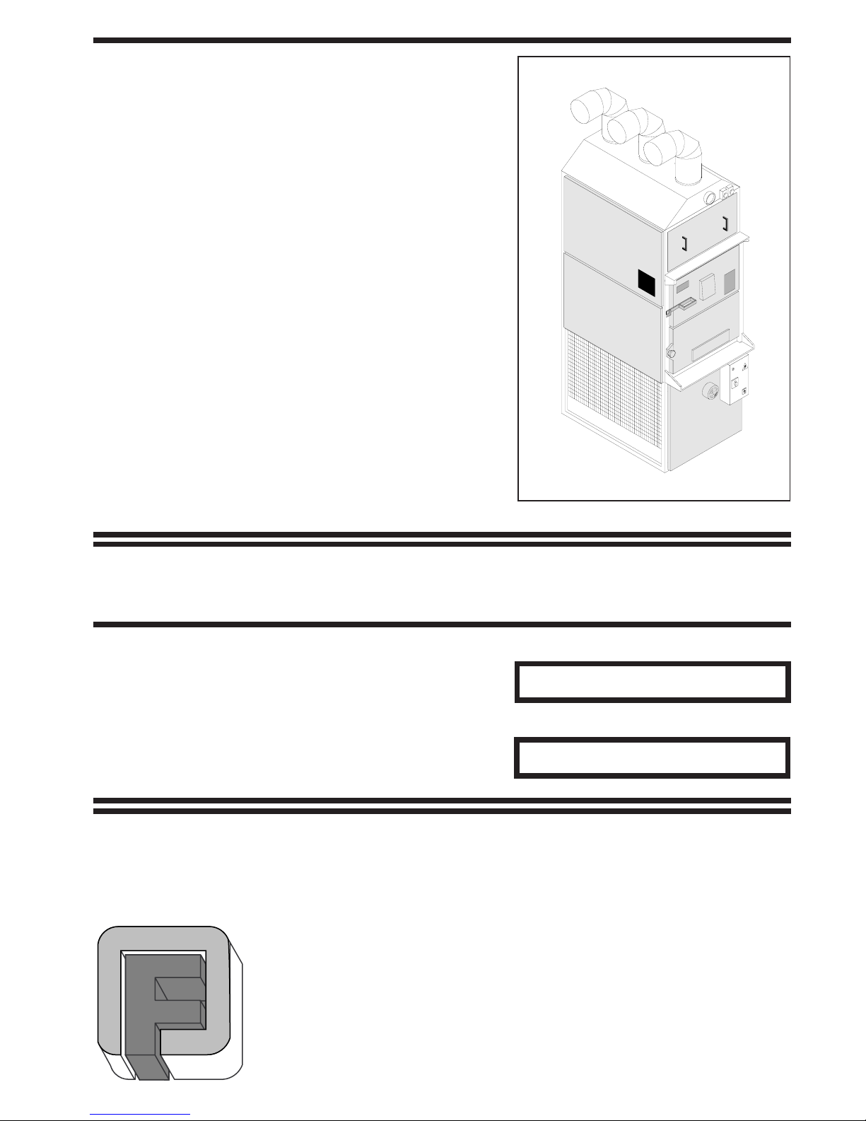
1.1 MACHINE DESCRIPTION ...................................................................................................................................... 5
1.2 APPLIED RUGULATIONS ....................................................................................................................................... 5
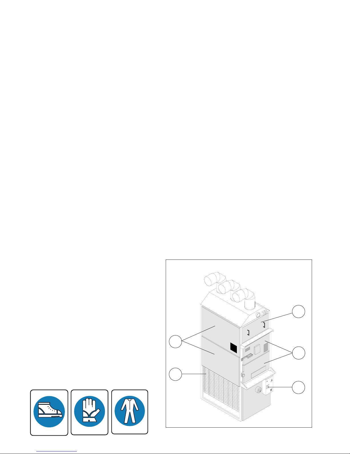
1.3 WORK STATION ..................................................................................................................................................... 6
1.4 PROTECTIONS ........................................................................................................................................................ 6
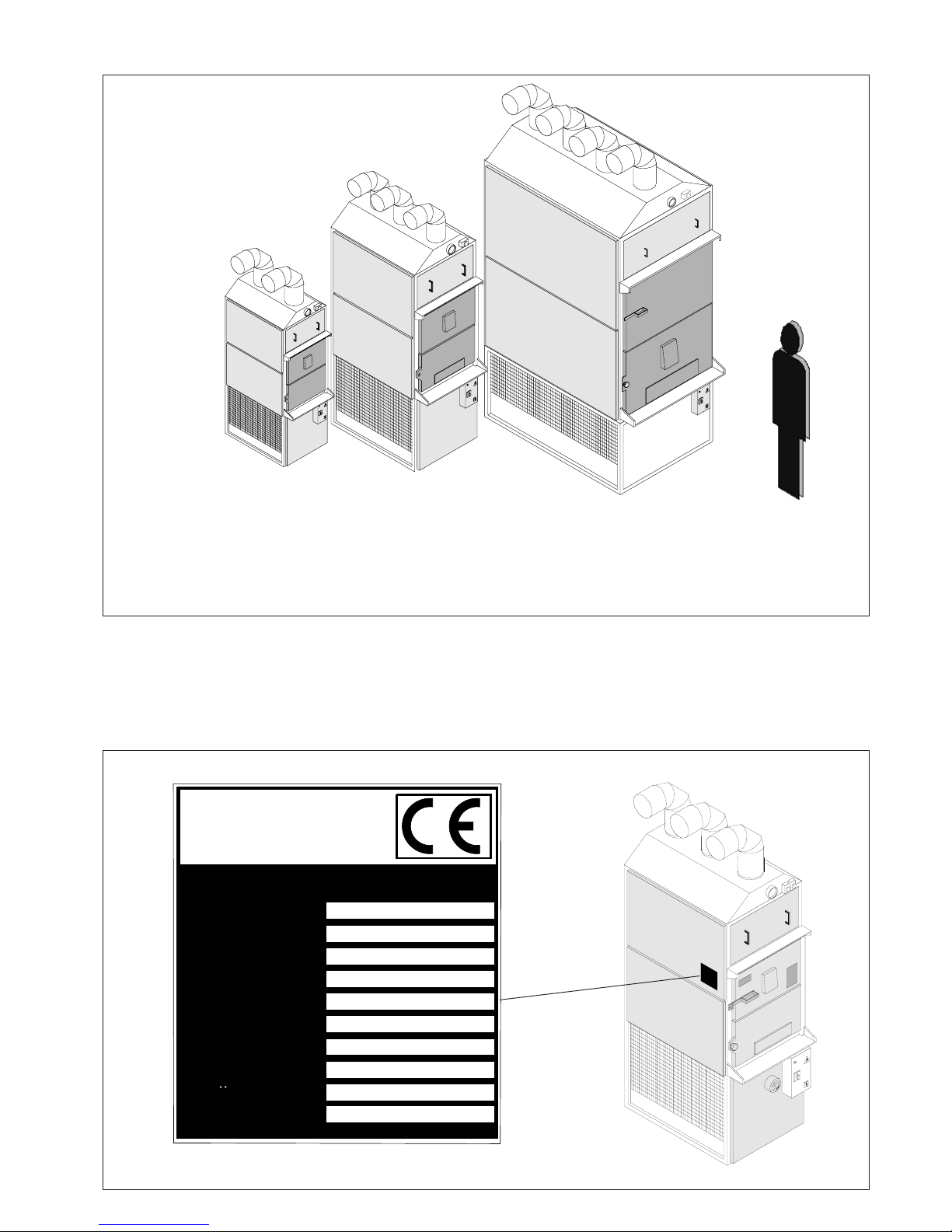
1.5 MODELS .................................................................................................................................................................. 7
1.6 IDENTIFICATION ................................................................................................................................................... 7
1.7 ENCUMBRANCE .................................................................................................................................................... 8
1.8 LABELLING ............................................................................................................................................................ 8
1.9 TECHNICAL SPECIFICATIONS ............................................................................................................................ 9
2 INSTALLATION .......................................................................................................................... 10
2.1 TRANSPORT ............................................................................................................................................................ 11
2.2 LIFTING AND HANDLING .................................................................................................................................... 11
2.3 ACCESSORIES ........................................................................................................................................................ 11
2.4 ENVIRONMENTAL SPECIFICATIONS ................................................................................................................ 12
2.5 INSTALLATION ...................................................................................................................................................... 13
2.6 MAINTENANCE SPACE ........................................................................................................................................ 13
2.7 ELECTRIC PLUG-IN ............................................................................................................................................... 14
3 OPERATION ................................................................................................................................ 16
3.1 PRELIMINARY CONTROLS (version F85 CV - F120 - F240) .............................................................................. 16
3.2 STARTUP ................................................................................................................................................................... 16
3.2.1 STARTUP (summer) ............................................................................................................................................... 16
3.3 TWIN THERMOSTAT FUNCTIONING ................................................................................................................. 17
3.3.1 FAN FUNCTIONING ............................................................................................................................................. 17
3.3.2 LIMIT FUNCTIONING ......................................................................................................................................... 17
3.3.3 PLUGGING AND CALIBRATION ....................................................................................................................... 17
3.1 PRELIMINARY CONTROLS (version F85 SV) ...................................................................................................... 18
3.1.2 CONTROLS DESCRIPTION ................................................................................................................................. 18
3.2 STARTUP ................................................................................................................................................................... 18
3.2.1 STARTUP (summer) ............................................................................................................................................... 19
3.4 OPERATION .............................................................................................................................................................. 20
3.5 REGULAR STOP ...................................................................................................................................................... 20
4 ORDINARY MAINTENANCE .................................................................................................. 21
4.1 PRELIMINARY CONTROLS ................................................................................................................................... 21
4.2 CLEANING THE WARM AIR GENERATOR ......................................................................................................... 21
4.2.1 WIPING OFF THE ASH ......................................................................................................................................... 22
4.2.2 CLEANING THE FLUE ......................................................................................................................................... 22
4.2.3 CLEANING THE HEAT EXCHANGER ............................................................................................................... 22
4.3 FANBELT STRETCHING ......................................................................................................................................... 22
4.4 REPLACING THE THERMOSTAT PROBE (version F85 SV) ............................................................................... 23
4.5 REPLACING THE FUSE (version F85 SV) ............................................................................................................. 23
5 END OF SERVICE ..................................................................................................................... 24
6 ACOUSTIC POLLUTION ......................................................................................................... 24
7 SPARE PARTS CATALOGUE .................................................................................................. 25
TAV. 1 SPARE PARTS F85 ............................................................................................................................................. 26
TAV. 2 SPARE PARTS F120-240 ................................................................................................................................... 27
TAV. 3 ELECTRIC PLAN F85-1SV ................................................................................................................................ 28
TAV. 4 ELECTRIC PLAN F85-2SV ................................................................................................................................ 29
TAV. 5 ELECTRIC PLAN F85-1CV ............................................................................................................................... 30
TAV. 6 ELECTRIC PLAN F85-2CV ............................................................................................................................... 31
TAV. 7 ELECTRIC PLAN F120-1 ................................................................................................................................... 32
TAV. 8 ELECTRIC PLAN F120-2 ................................................................................................................................... 33
TAV. 9 ELECTRIC PLAN F240-1 ................................................................................................................................... 34
TAV. 10 ELECTRIC PLAN F240-2 ................................................................................................................................. 35

5
1 TECNICAL SPECIFICATIONS
1.1 MACHINE DESCRIPTION
This machine is a warm air generator which operates with solid fuel.
The framework is made up of a square profiled steel chassis and panels in galvanized polished steel.
On the chassis’ lower part are located the vents for the air to be heated, which push the air inside the heat
exchanger. The air is then expelled by exhaustion vents on the upper part of the machine.
The combustion chamber is chrome INOX steel, reinforced with ribs, and it is placed above the vents.
Inside, the furnace is separated from the cinerary by a steel grid.
The loading doors on the back of the machine are steel and internally coated in refractory materials. On the
lower door you will find the shutter for regulating the combustion chamber’s power.
The upper door, with a handle, is used to load fuel in the machine.
The fumes’ exhaust pipe in the combustion chamber is linked to the heat exchanger above it.
The heat exchanger is made up of a series of pipes that run down the back and are linked to the draft mechanism,
which is in turn operated by an external engine (except in the F85SV model).
On the control panel you will find the switches to start up the draft engine and the air heating vents.
1.2 APPLIED REGULATIONS
Summary of laws and harmonized and technical rules
1. Directive CEE 98-37 (Directive regarding Machines).
EN 292/1 Machine safety – fundamentals, general design principles – terminology, basic methodolo-
gy.
EN 292/2 Machine safety – fundamentals, general design principles – technical specifications and
principles.
EN 294 Machine safety – safety distance to avoid upper arms to make contact with dangerous parts
- 1992.

6
EN 563 Machine safety – contact surface temperature. Ergonomic data to establish temperature va-
lues limits for heated surfaces. (june 1994).
UNI 8364 Heating systems – checkup and maintenance.
2. Directive CEE 73-23 (Directive regarding low tension).
EN 60204-1 Machine safety – electric equipment Part 1 general requirements. - 1992 (revision of EN
60204-1).
EN 60529 Casing protection degrees (june 1991)
EN 60445 identification of terminals and drawn conductors, and rules for the alphanumeric
3. Directive CEE 89-336 (Directive regarding EMC - electromagnetic compatibility).
EN 50081-2 electromagnetic compatibility – generic emission rule. Part 2: industrial environment
EN 50082-2 electromagnetic compatibility – generic immunity rule. Part 2: industrial environment.
1.3 WORK STATION
The machine need not be manned, therefore there is no need for an operator to use it, just to periodically reload
fuel.
The operator’s presence is required only when combustion is started.
1.4 PROTECTIONS
The machine is equipped with the following safety systems (Fig.1):
- Protection of the power grid with doorlock (pos.A).
FIG.1
E
B
A
C
D
- Mechanical protection in the loading area, coated
in refractory materials (pos.B).
- Permanent mechanical protection using a galva-
nized steel sheet on the machine’s sides (pos.C).
- Mechanical protection using a metal grid in the
vents’ suction tract (pos.D).
- Mechanical protection using a steel sheet reinforced
with refractory materials in the heat exchanger’s
inspection tract (pos.E).
- Alarm (pos.F) (models F240-120 and F85SV
only).
Furthermore, for the operator’s safety we recom-
mend:
- Protective suits
- Shockproof shoes
- Protective gloves

7
1.5 MODELS
MOD. F350
MOD. F28
MOD. F55 S.V.
MOD. F55 C.V.
MOD. F85 S.V.
MOD. F85 C.V.
MOD. F120
MOD. F240
FIG.2
FIG.3
1.6 IDENTIFICATION
When contacting the manufacturer, always provide the machine’s serial number and year of manufacturing,
found on the plate affixed on the right hand side (see fig.3).
GENERATORE DI ARIA CALDA
APPARECCHIO TIPO
ANNO DI COSTRUZIONE
NUMERO DI SERIE
TENSIONE
POT.ELETTRICA
PORT. ARIA
COMBUSTIBILE
PESO
POT.TERMICA RESA
POT.MASS. FOC.
Via Cangiotti, 10 - 61100 - Pesaro - Italia
Tel. 0721.282537 - FAX 0721.282970
3
FABBRI
TERMOMECCANICA S.r.l
KW
KW
KW
V
LEGNA
kg
m /h
KCal/h
KCal/h

8
1.6 IDENTIFICATION
FIG.5
1.8 LABELLING
The machine features warning labels in the indicated areas (fig.5).
FIG.4
F28
560
1560
1900
920
920
170
A (mm)
B (mm)
B1 (mm)
C (mm)
C1 (mm)
WEIGHT (kg)
MODELS F55 S.V.
690
1750
2100
1150
1150
260
F55 C.V.
690
1750
2100
1150
1520
305
F85 S.V.
800
1980
2400
1280
1280
365
F85 C.V.
820
1980
2400
1280
1690
415
F120
930
2200
2600
1700
2060
615
F240
1100
2500
3000
1900
2290
850
F350
1220
3000
3400
2700
3160
1575
WERNING
1) BEFORE LIGHTING THE FIRE
ENSURE THAT THE FAN TURN
IN THE RIGTH DIRECTION AND
THE THERMOSTAT WORKS.
2) FOR A GOOD RUNNING OF
THE GENERATOR USE ALL THE
SOLID COMBUSTIBLES
ALLOWED BY LAW.
3)LOAD WITH MODERATION; A
POWER CUT COULD MELT THE
THERMOSTAT AND DILATE THE
OVEN.
4) AT THE END OF EACH
HEATING SEASON UNDERTAKE
A GENERAL CLEANNING OF
THE GENERATOR.
5) DO NOT USE POWDER
COMBUSTIBLES OR SAWDUST.
ATTENTION
HIGH
SURFACE
TEMPERATURES
AVVERTENZE
1) PRIMA DI ACCENDERE IL
FUOCO ASSICURARSI CHE LE
VENTOLE GIGINO PER IL VERSO
GIUSTO.
2) PER UNA BUONA GESTIONE
DEL GENERATORE USARE TUT-
TI COMBUSTIBILI SOLIDI
BERMESSO DALLA LEGGE
3) CARICARE MODERATAMEN-
TE; PERCHE' UN BLACK-OUT DI
CORRENTE POTREBBE FONDE-
RE IL TERMOSTATO E
DILATARME IL FORNO.
4) AL TERMINE DI OGNI STAGIO-
NE DI RISCALDAMENTO EFFET-
TUARE UNA PULIZIA GENERA-
LE DEL GENERATORE
5) NUN UTILIZZARE COMBUSTI-
BILE IN POLVERE O SEGATURA
DI LEGNO.
ATTENZIONE
SUPERFICE
TEMPERATURE
ELEVATE
HINWEIS
1) VOR DEM ANZÜNDEN DES
FEUERS SICH VERGEWISSERN,
DAß DIE LÜFTERRÄDER IM
RICHTIGEN SINN DREHEN UND
DER THERMOSTAT.
2)FÜR EIN GUTES
FUNKTIONIEREN DES
GENERATORES JEGLICHEN
VOM GESETZ ERLAUBTEN
FESTEN BRENNSTOFF
VERWENDEN.
3)GEMÄßIGT AUFLADEN, DENN
EIN STOMAUSFALL KÖNNANTE
DEN THERMOSTAT
SCHMELZEN UND DEN OFEN
DEHNEN.
4) AM ENDE JEDER
HEIZPERIODE EINE GENERELLE
REINIGUNG DES GENERATORS
DURCHFÜHREN.
5)KEINE BRENNSTAUB ODER
HOLZMEHL VERWENDEN.
ACHTUNG
HEIßE
OBERFLÄCHE
B1
B
A
C1
C

9
1.9 TECHNICAL SPECIFICATIONS
MODELS
DATA
F28 F55 F85 F120 F240 F350
Fuel WOOD - CHIPPINGS – TURF
Furnace power (Kcal/h) 29900 69000 99500 150000 300000 437000
(KW) 34 80 115 175 350 510
Effective convention-
al power (Kcal/h) 25000 55000 80000 120000 240000 350000
(KW) 29 64 93 140 279 407
Air intake (m3 /h) 2200 3500 6300 8900 17800 26000
Fuel consumption
(Kg/h) 13 20 30 43 85 125
Vents electric power
(HP) 0,2 0,35 1,5 3 4 6
Suction vents electric
power (HP) - 0,35 0,35 0,75 0,75 1,5
Engine voltage (V) 220
(monoph.)
220
(monoph.)
380
(triph.)
380
(triph.)
380
(triph.)
380
(triph.)
Chimney diameter
(mm)
(models without
fumes vent)
160 Ø 180 Ø 180 Ø -------- -------- --------
Chimney diameter
(mm)
(models with fumes
vent)
-------- 180 Ø 180 Ø 200 Ø 200 Ø 250 Ø
Exhaust pipes diam-
eter (mm) 2x180Ø 2x200Ø 2x250Ø 3x250Ø 3x300Ø 4x350Ø

10
2 INSTALLATION
WARNING!
The generator’s installation must be performed in observation of the current laws and technical
rules, and its design must be performed by a freelance professional with regular profession
registration
HEATING SYSTEM DESIGN AND INSTALLATION
Law n. 46, 5th May 1990.
“Rules for systems safety”.
Law n.10, 9th January 1991.
“Rules for enforcing the national energetic plan regarding energy rationing, energy saving, and development
of renewable energy sources”.
Presidential Decree n. 447, 6th December 199.
“Rules for applying the Law n. 46, 5th May 1990, regarding systems safety.”
Presidential Decree n.412, 26th August 1993
“Rules for designing, installing, operating and maintaining heating systems in buildings towards the lowering
of consumptions in respect of art. 4, paragraph 4 of the Law n.10, 9th January 1991.”
RULES FOR PREVENTING POLLUTION DURING HEATING SYSTEM INSTALLATION.
Law n. 615, 13th July 1966.
“Rules against pollution”.
Presidential Decree n. 1391, 22nd December 1970.
“Rules for applying Law n. 615, 13th July 1966 with rules to prevent pollution, regarding heating systems”.
RULES FOR PREVENTING FIRES DURING HEATING SYSTEM INSTALLATION.
Minister of Internal Affairs Draft n.73, 29th July 1971.
“Heating systems operating with oil fuel or oil gas – Rules against pollution. Rules to prevent fires.”
Presidential Decree n.689, 26th May 1959.
“Indication of companies and operations subject to controls by the Firefighters Command in order to prevent
fires.”
Ministerial Decree 16th February 1982.
“Changes to Ministerial Decree 27th September 1965, dealing with companies subject to controls to prevent
fires.”
Decree n.246, 16th May 1987.
“Rules for fire prevention in civilian buildings.”

11
INSTALLATION RULES FOR THE ELECTRIC SYSTEM’S SAFETY.
Law n. 186, 1st March 1968.
“Rules for producing and installing electrical and electronic systems, materials, and machines.”
Italian Electro-technical Committee Rule 64-8.
Electric systems operating at a nominal tension non above 1000 V A/C and 1500 V D/C
2.1 TRANSPORT
The machine can be transported via truck, ship, train, and plane.
The machine is usually shipped wrapped in nylon, and the suction engine is dismantled.
All accessories are shipped separately.
2.2 LIFTING AND HANDLING
The machine can be lifted with a crane or freight elevator, using two hooked, clasped tows at least 1 meter
long, or with a fork lift.
If lifted with a crane or freight elevator:
Place the hook end of the tows on top, and in the eyebolt in the lower part (fig. 6), placed in the plates welded
on the exchanger.
WARNING!
Lifting the machine with shorter tows can damage its upper parts.
2.3 ACCESSORIES
The only accessory for the machine is the fumes purifier, available on demand.
FIG.6

12
2.4 ENVIRONMENTAL SPECIFICATIONS
While positioning the machine, keep in mind that its functioning is guaranteed under an ambient temperature
between 5°C and 40°C, and relative humidity between 35% and 75%
2.5 INSTALLATION
- Package
Do not throw the package in the trash, instead separate the various components according
to materials (cardboard, wood, steel, polyester, and so on) and dispose of them according to
your Country’s laws
The machine needs a solid support on the floor.
Position the machine according to its designated space.
Install the warm air diffusion vents (pos. 2 fig.7a-7b-7c).
IF THE MACHINE HAS THE FUMES VENT:
Install the fumes aspiration system (pos.4 fig.7a-7b-7c).
Install the various tracts of the warm air generator’s flue (pos.4, 5, 6 fig.7a-7b-7c).
WARNING!
You must install at least one special pipe T-shaped element in the flue (pos.7 fig.7a-7b-7c),
which helps in cleaning operations.
MODELS F85 WITH FUMES VENT FIG.7a
6
7
1
26
5
7
2÷3 mt. 4
C
PROTECTION DURING
PLUGGING OF THE ELECTRIC
POWER CABLE
C

13
WARNING!
The initial vertical section of the flue should never measure more than 2 or 3 meters in length
(pos. 5 fig.7a-7b-7c) before applying the T-shaped tract (pos.7 fig.7a-7b-7c).
6
1
2
2÷3 mt. 4
5
7
6
7
3
PROTECTION DURING
PLUGGING OF THE ELECTRIC
POWER CABLE
MODELS F85 WITHOUT FUMES VENT FIG.7b
MODELS
F120
F240
PROTECTION DURING
PLUGGING OF THE ELECTRIC
POWER CABLE
1
2E
B
6
4
3
C
6
5
7
2÷3 mt.
FIG.7c

14
2.6 MAINTENANCE SPACE
During installation of the machine, it is advisable to set up an area for later maintenance operations, as indicated
in fig. 8.
IMPORTANT: the values in the tables are the recommended minimum values.
2.7 ELECTRIC PLUG-IN
WARNING!
Before plugging in, make sure you have a proper grounding system which follows the current
European Laws (EN).
Check the compatibility of the network voltage with the specificatins in the appropriate label
in the machine (fig. 2).
Power fluctuations greater than ±10% of the nominal voltage indicated in the label can cause
serious damage on the machine. That damage in not covered by the warranty.
IMPORTANT: verify that the power cable is the right size.
Turn the switch on the 0 position in the F85 CV-F120-F240 models (pos. A fig.11), in the F85 (pos. A
fig.11B).
Insert the machine’s power cable through the gland under the power grid (pos. B fig.7). Connect wires in the
terminal by following the attached electric plan (TAV. 2) and following.
IF THE MACHINE HAS THE FUMES VENT:
Plug the fumes suction grid’s cable (pos. C fig.7).
Once the cable has been plugged, the suction vents’ orientation should be checked.
In the F85 CV-F120-F240 models, proceed as follows:
- Turn on the manual operation of the vents’ thermostat (press the white button) (fig.9);
- Turn on the general switch (fig.10);
The values in the table are expressed in mm.
F28
F55
F85
F120
F240
F350
1000 600 600 1500
1000 600 600 1500
1000 600 600 1500
1200 600 600 1800
1200 600 600 1800
1200 600 600 2000
A B C D
A
B
D
C
FIG.8

15
- Make sure the vents’ orientation in correct (refer to the arrows on the fans)
WARNING!
Should this checkup be skipped, the combustion chamber could be damaged during the first
startup, due to overheating of the entire machine.
In the F85 SV model, proceed as follows:
- Turn on the general;
- Press the “FAN” button to start up the vents (fig.10b);
- Make sure the vents’ orientation in correct (refer to the arrows on the fans)
1
ALARM
FAN
SMOKE
FAN
SMOKE
TEMPERATURE°C
FIG.10FIG.9
FIG.10b

16
3 OPERATION
In the F85CV - F120- F240 models
3.1 PRELIMINARY CONTROLS
WARNING! Before starting up the
machine make sure that:
- The power grid’s general switch is turned
off (pos. OFF).
- The machine’s general switch is turned
on 0 (pos.A fig. 11).
- All installation and assembling has been
performed correctly, especially during
orientation of the vents.
3.2 STARTUP (summer)
Turn on the machine’s general switch (fig.11 pos.B).
Turn on the fumes vent by pressing its button (fig.12
pos.1).
Load the fuel using the grid in the machine’s upper
part.
Turn on fuel loading and wait for combustion to start
up.
WARNING!
Do not use liquid fuel.
WARNING!
If the machine has got a fumes vent, do
not turn it off during combustion.
To adjust combustion, regulate suction power in the
lower (fig.13 pos.3).
The thermostat that regulates the vents’ startup is already
set at a temperature between 30°C and 40°C.
The alarm’s thermostat is already set to activate at
90°C.
When the desired temperature has been reached, the
air vents will activate automatically (press the white
button, turn it on automatic position) (fig.14).
3.2.1 STARTUP (summer)
IMPORTANT: to turn on cold air
circulation, press the fumes vent
button (pos.3 fig.16) in absence of
combustion.
0
1
0
1
0
1
A
B
FIG.11
1
0
FIG.12 Fumes vent for solid
combustion
FIG.13
3
2
1
FIG.14
Off fumes
ven

17
3.3 TWIN THERMOSTAT OPERATION
The thermostat’s sensor is placed on the suction vent. It can start and stop the ventilation system (FAN function),
and regulates the overheating alarm mechanism (LIMIT function) when it is available.
3.3.1 FAN FUNCTION
When the ambient temperature near the sensor reaches the value set on the twin thermostat’s board (40°C), an
electric contact in the thermostat will be closed, and the ventilation system will activate.
When the ambient temperature near the sensor drops lower than the value set on the twin thermostat’s board
(30°C) an electric contact in the thermostat will be opened, and the ventilation system will stop.
3.3.2 LIMIT FUNCTION
When the air in proximity of the sensor is overheated due to an anomaly, and the temperature reaches the value
set on the twin thermostat’s board (100°C), an electric contact in the thermostat will be closed, and the alarm
will activate.
3.3.3 PLUGGING AND CALIBRATION
The warm air generator’s wirings are already plugged, and the twin thermostat is already calibrated. Should
you need to perform those operations again (in case of maintenance, checkups, or replacements), please follow
the instructions below (fig. 15):
Legend:
1. Wirings for FAN function.
2. Twin Thermostat’s board.
3. Fastening holes.
4. Ventilation system’s stop temperature indicator.
5. Ventilation system’s start temperature indicator.
6. LIMIT function’s activation temperature indicator.
7. Holes for wires block. By inserting the tip of a screwdri-
ver in this hole, the clamp will be blocked, and it will
be possible to insert a wire. Removing the tip of the
screwdriver will automatically block the wire inside
the clamp.
WARNING! Make sure the wire is tightly
blocked inside the clamp by gently pulling
it.
8. Wirings for LIMIT function.
9. Metal bridge10.
White button for automatic (raised) or manual (pressed) ventilation.
IMPORTANT!
The metal bridge (9) must be removed in all models.
When adjusting values (4) (5) (6) do not turn the board (2), or the twin thermostat will be
damaged.
FIG.15

18
Model F85 SV only.
3.1 PRELIMINARY CONTROLS
WARNING! Before starting up the machine make sure that:
The power grid’s general switch is turned off (pos. OFF).
The machine’s general switch is turned on 0 (pos.1 fig. 11).
All installation and assembling has been performed correctly, especially during orientation
of the vents.
3.1.2 CONTROLS IN THE ELECTRONIC PANEL
1) General switch.
2) fumes vent button.
3) air vent button.
4) fumes vent light (green).
5) air vent light (green).
6) alarm light (red).
7) temperature display.
3.2 STARTUP
Turn on the machine’s general switch (pos.1B fig.11).
Load the fuel using the grid in the machine’s upper part.
Turn on fuel loading and wait for combustion to start up.
WARNING!
Do not use liquid fuel.
WARNING!
If the machine has got a fumes vent, do not turn it off during combustion.
ALARM
FAN
SMOKE
FAN
SMOKE
TEMPERATURE°C
2
3
4
5
6
7
FIG.16

19
To adjust combustion, regulate suction power in the lower door (pos.3 in fig.13).
When temperature reaches 45°C, the air vents will activate automatically (pos.5 in fig.16), and they will
automatically switch off as well when temperature drops below 41°C.
The alarm’s thermostat is already set to activate at 90°C.
3.2 STARTUP (summer)
IMPORTANT: to turn on cold air circulation, press the fumes vent button (pos.3 fig.16) in
absence of combustion.

20
3.4 OPERATION
The machine must only be loaded with fuel via the upper door (pos. 1 in fig.13). Fuel examples include:
- Dry wood not treated with chemicals.
- Wood chippings pressed in bundles.
WARNING! Do not use powdered wood, nor liquid fuel, during startup and combustion.
Removing ashes.
Remove ashes only after combustion has ceased, and only after temperature has dropped below 40°C, then:
- open up the two front doors (pos. 1 and 2 in fig.13).
IMPORTANT: the lower door will not open if the upper door is open.
The lower door is closed with a knobbed screw.
- Empty the cinerary.
- Close the doors.
IMPORTANT: do not place the ashes near the vents’ suction area (fig. 17).
NO
FIG.17
WARNING! Do not overload the machine. An
excessive heat generated by combustion could
deform the machine’s structure.
When the warm air generator is on, there is
a chance that the alarm will be set off. This
is due to the excessive heat generated by the
furnace. In this case, lower the heat generation
by shutting down the air suction (pos. 3 in fig.
13), and stop loading fuel.
WARNING! Do not let the alarm activated
for more than 2 minutes, or the wirings could
be damaged.
3.4 REGULAR STOP
You can turn off the furnace by shutting down the air suction (pos. 3 in fig. 13)
Then, after the machine has cooled down, switch off the flue’s suction and the vents (pos. 0 in fig. 11), and
finally turn off the machine’s general switch.
WARNING!
Do not turn off the general switch before combustion has ceased and the ashes are cold.
This manual suits for next models
2
Table of contents
Popular Heater manuals by other brands

Noirot
Noirot Sport Plus Operating & installation instructions

Tulikivi
Tulikivi SS036 manual

Biddle
Biddle KLVV User manual installation - maintenance

Rapid Engineering
Rapid Engineering UHAT 150 Installation, operation & service manual

EOS
EOS Bi-O Mat U Assembly and operating instruction

DeLonghi
DeLonghi OIL FILLED RADIATORS instructions