Function This control is a complete control cabinet for milkcooling tanks. The
integrated microprocessor regulator with automatic afterstirring has
separate relay contacts for the compressor contactor and the stirrer. The
measured milk temperature is shown constantly on the display, when
the cooling mode is switched on.
Two freely adjustable target temperatures may be selected by push
buttons. Should the milk temperature exceed the chosen target tempe-
rature (4° or 8°) by the hysteresis value, the compressor and stirrer are
automatically switched on. Once the target temperature is reached, the
compressor contactor switches off. The stirrer continues for the pro-
grammed period. During refrigeration pauses, the stirrer automatically
switches on again according to the programmed intervals, to ensure an
even temperature throughout the milk.
Independently of this, short or long "intermediate stirring" can be selec-
ted by pressing a button. Software can also be used to programme for
"permanent stirring", i.e. the agitator is switched on and off by pressing a
button.
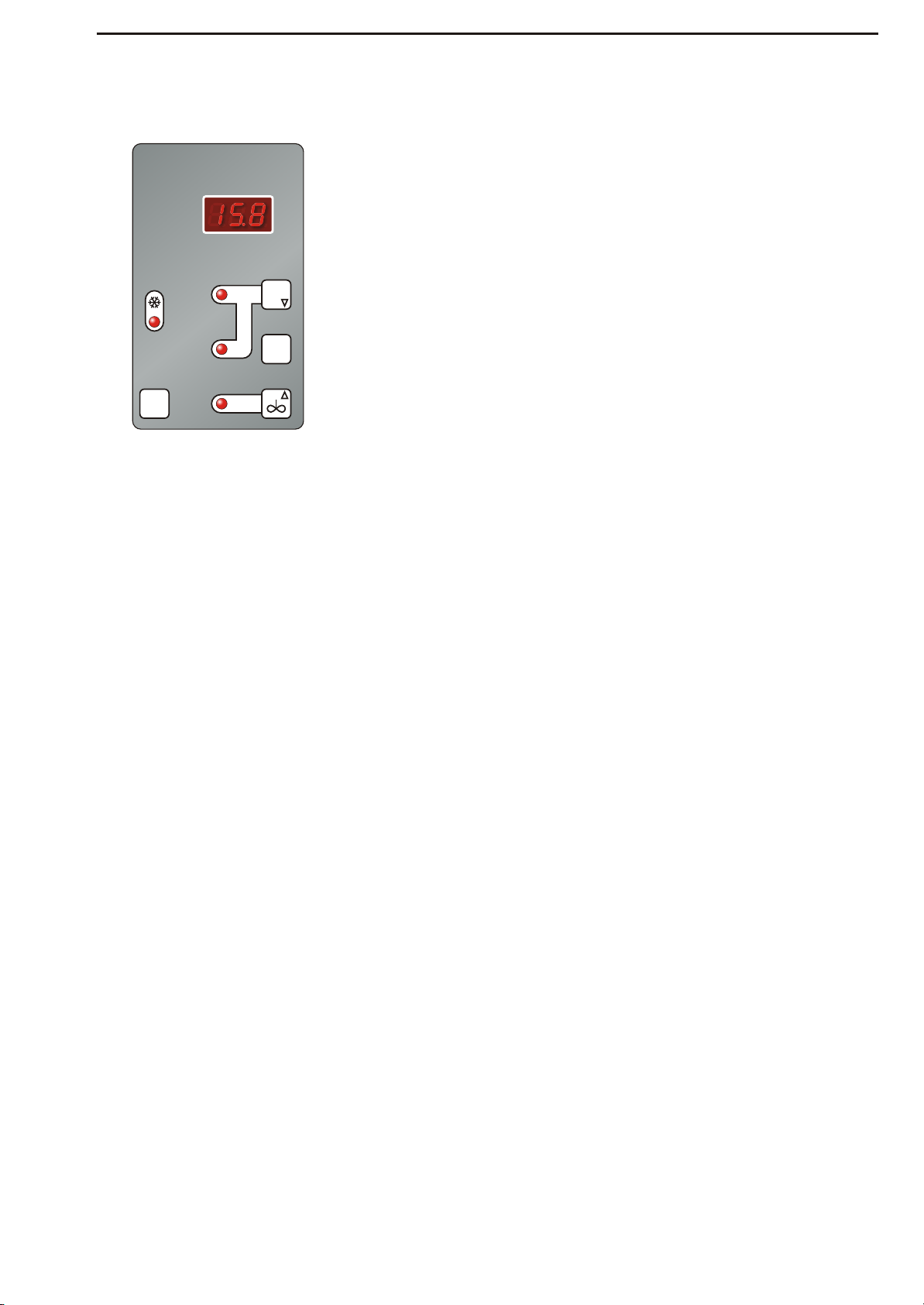
Cooling mode
Press the "4°/8°" button: the compressor and agitator operate automati-
cally. In between cooling periods (agitator and compressor LEDs off),
intermediate stirring can be activated.
Stirring mode
If stirring mode is active: (temperature shown in display)
!"Short" intermediate stirring:Briefly press the "Agitator" button."sho"
appears in the display, and the agitator starts to operate.
!"Long" intermediate stirring:Press and hold down the "Agitator" button
for 5 seconds."lon" appears in the display, and the agitator starts to
operate.
!Continuous stirring (only if set at parameter level):Press the"Agitator"
button. "On" appears in the display. The agitatoroperates continuously
until the "Agitator" button is pressed again.
If OFF mode is active: (Display is dark)
!Continuous stirring while cooling is switched off:Press the "Agitator"
button. A rotating bar is shown in the display, and the agitator operates
continuously, until you press the button 'STOP'.
Off mode
The regulator can be switched off using the "STOP" button (Display and
LEDs dark). Both the output relays for the agitator and compressor are
deactivated.
CAUTION: The regulator is live even when switched off.
4° / 8°
Switch between target temperatures (when cooling mode is active only)
Page 3