FABIO LEONARDI MR 2 User manual

Ogni macchina delia serie MR
puo essere combinata con
diversi accessori.
Consultare la seguente tabella
per verificare Ie diverse
applicazioni.
Each machine in the MR series
can be used in combination
with avariety of accessories.
Consult the following table to
• check the various applications.
Chaque appareilde la serie MR
peut ~tre utilise avec differents
accessoires.
Consulter Ietableau ci-dessous
• pour verifier les differentes •
• applications.
Die Maschine der Serie MR
konnen mit verschiedenen
• ZubehOrteilen kombiniert
werden.
PrOfen Sie die verschiedenen
Einsatzbereiche anhand der
nachstehenden Tabelle
TC5 TC8 TC 12 TC22 TC32 SP2 SP3 SP5
MR2 HpO,25 ••
MR2C HpO,25 ••
MRO HpO,50 ••••
MR8 HpO,50 •••
MR9 HpO,7 ••• •
Hp 1,0
MR7 Hp1 ••••
-
,
MR 10 Hp 1,3 ••••
Sulla macchina sono applicate
delle targhette relative alia
sicurezza ed aile caratteristiche
delia macchina stessa.
Richiederne copia alia ditta
costruttrice se dovessero
risultareiIIeggibili.
Plates indicating the safety
guidelines and machine
• characteristics are applied to
the machine.
Should they become illegible
acopy should be requested •
from the manufacturer.
.~~~M::~~~~
PRODOTTI A NORMA (
E
EMPLACEMENT DES PLAQUES •
ANORONUNG OER
• PLAKETTEN
Sur la machinesont appliquees
des plaques relatives
a
la
securite et aux caracteristiques
de la machine.
Si elles devaient devenir
illisibles, il suffit de demander
des plaques de remplacement
au fabricant.
• An der Maschinesind Plaketten
• mit Angaben zur Sicherheit und
• zu den Cigenschaften der
Maschine selbst angebracht.
Sollten die Plaketten
unleserlich werden, fordern Sie
neue bei der Herstellerfirmaan.
----ATTENZIONE-4 --
STACCARE LA SPINA DALLA PRESA
PRIMA 01 QUALSIASI OPERAZIONE
F L B
TEL. 051/732377
• • • FAX. 051/732701
MOTORE ASINCRONO
TipOI ~
HP
-I---I
Giri
1
I
V. c=:J c::::::J A c=:J c::::::J
Hz. c=:JCos(j>c=:Jls.CI.c=:J
Prot.1 I
t
1
.-

2.1 CONFIGURAZIONE
TRITACARNE TC
Ad ogni modello MR, in base alia
tabella del par. 1.4,
e
possibile
applicare i componenti per la
trasformazione in tritacarne
delia serie TC.
MINCER TC CONFIGURATION • CONAGURAll0N
: HACHOIRTC
• As
indicated in the table in sect.
1.4, it is possible to apply
components to each MR model
to convert to
a
TC
series mincer.
• Surchaque rnod8le MR, sur Iabase
• du1abIeaudu par.1.4,iIestpossible
• d'appliquer les composants pour
: la transformation en hachoir de la
• serieTC.
Beijedem MRModellkonnengemaB
der Tabe/le im Abs.
1.4
die
• KomponentenzurUmfonnungineinen
: Fleischwoffder Serie TCeingesetzt
werden.
• AVERTISSEMENTS • ~
• CONCERNANT LE MONTAGE
2.3 COMPONENTI KIT TC TC KIT COMPONENTS • COMPOSANTS KIT TC KOMPONENTEN KIT TC
1) Pestello
1)
Pusher
• 1) Pilon
' 1)
StOBei
2) Vasca prod otto
: 2)
Product tank
: 2) Collecteur produit :2
Produktwanne
3) Corpo tritacarne
, 3)
Mincer body
• 3) Corps hachoir
• 3)
FleischwoffgehBuse
4) Attacco elica
' 4)
Rotor fitting
• 4) Fixation helice
• 4)
Schraubeneinsatz
5) Raila
5)
Fifth wheel
• 5) Butee
'5)
Drehplatte
6) Elica
6)
Rotor
: 6) Helice
: 6)
SChraube
7) Gambo quadro
7)
Square shaft
• 7) Tige carree
• 7)
Vierkantschaft
8) Coltello
8)
Blade
• 8) Couteau .8
Messer
9) Piastra
9)
Plate
• 9) Plaque
9)
Platte
10) Anello chiusura
10)
Closure ring
10) Bague de blocage
10)
Vef Ch'ussring
~2

Prima dl esegulre
n
montaggio
lavare accuratamente tutti
I componentl da montare
con deterslvo per
alimentl ed asclugarll.
• Svitare iI pomello di
bloccaggio corpo (fig. 3 rif. •
A) presente nei motori con
retromarcia.
• Infilare iI corpo del tritacarne
(fig. 3 rif. B) sulla flangia
motore.
• Ruotare iIcorpo tritacame (fig.3
rtf.C) e bIoccar1ocon iIpomeIlo
(fig. 3 rtf. 0).
• Inlilare net carpo, in sequenza i
seguenti componenti:
l'e1ica(fig. 3 rtf. E), avendo cura •
di lubrificare con un goccio di
olio per alimenti Ia guamizione
OR (fig. 3 rtf. F), iI coIleIlo (fig. 3
rif. G), prestando molta
attenzlone aile lame
taglient , la piastra forata (fig.
3 rtf. H), e I'anello di chiusura
(fig. 3 rtf. I) da awilare a fondo
sui corpo del tritacame.
• Inlilare nella bocca superiore del
corpo tritacarne la vasca di
raccolta prodotto (fig. 3 rtf.
L).
Before assembly, carefully
wash all components to be
• fitted
with
food-safe
detergent
and dry.
• Unscrew the body locking knob
(fig.
3
ref. A) in the motors with
reverse.
• Insert the body of the mincer •
(fig.
3
ref. B) onto the motor
flange.
• Tum the body of the mincer (fig.
3 ref.
C)
and lock
it
using the
knob (fig.
3
ref. D).
• Insert the following components
in sequence into the body:
the rotor (fig.
3
ref. E), taking
care
to lubricate the seal with
a
drop of
foocI-safe
oil OR (fig. 3
ref. F), the blade (fig.
3
ref. G),
taking great care with the •
sharp blades, the
drilled
plate
(fig.
3
ref. H), and the closure
ring (fig.
3
ref. I) to be fully
tightened on the body of the •
mincer.
• Insert the product tank into the
upper mouth of the mincer body •
(fig.
3
ref. L).
Avant d'effectuer Ie
montage, laver
soigneusement tous les
composants avec du produit
a
valsselie et les essuyer.
• Oevisser Ie bouton de blocage
du corps (fig. 3 ref. A) present
sur les moteurs dotes de •
marche arriere.
• Inserer Iecorps du hachoir (fig.
3 ref. B) sur la bride du moteur.
• Tourner Ie corps du hachoir
(fig. 3 ref. C) at Ie bloquer avec
Ie bouton (fig. 3 ref. 0).
• Introduire dans Ie corps, en
sequence, les composants
suivants: L'helice (fig. 3 ref. E),
en veillant
a
lubrifier au moyen
d'une goutte d'huile Ie joint
torique (fig. 3 ref. F),le couteau
(fig. 3 ref. G), en faisant tres
attention aux lames
tranchantes, la plaque
perforee (fig. 3 ref. H), et la
bague de blocage (fig. 3 ref. I)
qui doit etre vissee
a
fond sur
Ie corps du hachoir.
• Inserer dans la goulotte
superieure du corps du hachoir
Ie coliecteUr (fig. 3 ref. L).
Was chen Sle vor der
Montage sorgfaltlg aile zu
• montlerenden Komponenten
mlt lebensmltteltaugllchem
Spiilmlttel und trocknen Sle
• dlese.
• LDsenSiedenKnaufzur Sicherung
des Korpers (Abb.
3
Pos.
A)
bei
den Motaren mit Riiekwiirtslauf.
• Fiihren Sie den Fleisehwolfkorper
(Abb.
3
Pos. B) auf den
Motorflanseh.
• DrehenSieReischwolfkiirper(Abb.
3 Pos.
C)
und sichern Sie ihn mit
dem Knauf (Abb.
3
Pos. D).
• Fiihren Sienacheinanderfolgende
Komponenten inden Korper ein
Sehraube (Abb.
3
Pos. E), wobei
Sie dabei darauf aehten, die OR-
Riehtung (Abb.
3
Pos. F) mit
etwas 01 fiir Lebensmittel zu
sehmieren, das Messer (Abb. 3
Poo.
G),wobeiS/eh6chsfJe
VorsicIIt
bel den Schneldkllngen wanen
lassen,
diegelochte Platte (Abb.3
Pos. H) und den Versehlussring
(Abb.
3
Pos.I)
zum
Festschrauben
am
Boden
des
Fleischwolfk6rpers.
• Fiihren Sie die
Produktsammelwanne(Abb.
3
Pas.
L) in das obere Mundstiiek des
Fleisehwolfkorpers

• Accertarsi che I'alimentazione
elettricadelia retecorrisponda
a quella richiesta dalla
macchina e riportata sulla
targhetta del motore.
• Infilare la spina nella presa di
alimentazioneenergiaelettrica.
• Posizionare la carne da
lavorare nella vasca.
• Accendere la macchina con
I'interruttore in posizione "I".
• Inserire la carne nel foro
delia vasca utilizzando
esclusivamente il pestello in
dotazione.
Neimotoricon potenzadi 0,7HP
o superiore, e possibile la
rotazione del motore in senso
contrario per effettuare tentativi
di sbloccaggio rotazione:
premere I'interruttore in
posizione "II" solo per 2
0
3
impulsi, dopodiche, se
I'inconvenientepersiste,sideve
smontare il gruppo tritacarne.
• Ensure that the mains power
supply matches that required
by the machine, indicated on
the motor plate.
• Connect the plug to the mains
power supply.
• Place the meat to be
processed into the tank.
• Press the switch to position
"/" to switch on the machine.
• Guide the meat into the hole
in the tank using the supplied
pusher only.
Motors with
O.
THP or higher may
be run in the opposite direction
to attempt to clear the jam:
press the switch to position "//"
2 or
3
times only; then, if the
problem persists, the mincer
unit must be dismantled.
• S'assurer que I'alimentation
electrique du reseau
correspond
a
celie requise
par I'appareil et indiquee sur •
la plaquedu moteur.
• Introduirelafichedansla prise
d'alimentationelectrique.
• Placer
a
la viande
a
hacher
dans la cuve.
• Allumer la machine avec
I'interrupteuren position "I".
Introduire la viande dans
I'orificede lac uveen utilisant
exclusivement Ie pilon fourni
avec I'appareil.
Sur les moteursd'unepuissance
de 0,7HP ou plus,il est possible
de commander la rotation du
moteurdansIesensinversepour
effectuer des tentatives de
deblocagede la rotation:
EnfoncerI'interrupteurenposition
"II" pas plus de 2 ou 3 fois. Si
I'inconvenientdevait persister,il
• faut demonter Ie groupe hache-
• viande.
• Stellen Sie sicher, dass die
elektrischeStromversorgungdem
vanderMaschinegefordertenund
auf dem Typenschilddes Motors
angegebenenWertentspricht.
• Fiihren Sie den Stecker in die
Steckdose.
• • Orr:i7enSiedaszuV8'lilbeilSl rJeFleisch
inderWannean.
• SchaJtenSiedie Maschinemit dem
SchaIfTi'JderPrxilion
'r
ei1
• Geben Sie das Fleisch in das
Wanne. Verwenden Sie dazu
ausschlieBlichden mitgelieferten
StoBel.
BeidenMotorenmit einer Leistung
van 0,7 HP oder dariiber ist die
Drehung des Motors im
entgegengesetztenSinnmaglichum
: zu versuchen, die Drehbewegung
wiederfreizugeben:
DriickenSiedenMotornurfUr
2
oder
3 Impulsein die Position "II". Sollte
dieStOrungdannnichtbehobensein,
montierenSiedieFleischwolfgruppe
ab.

CONFIGURAZIONE SPREMI
POMODOROSP
Ad ogni modello MR, in base alia
tabella del par. 1.4,
e
posslbile
applicare i componenti per la
trasformazione in spremi
pomodoro delia serie SP.
TOMATO PRESS
CONFIGURATION
As indicatedin the tablein sect.
1.4, it is possible to apply
components to each MR model
to convert to an SP series
• tomato press.
1) Pestello
2) Vasca prodotto
3) Corpo spremi pomodoro
4) Perno
5) Molla frizione
6) Elica
7) Anello
8) Filtro
9) Scivolo convogliatore prodotto
1) Pusher
2) Product tank
3) Tomatopress body
4) Pin
5) Clutch spring
6) Rotor
7) Ring
8) Filter
9) Product chute
SP CONFIGURATION
PRESSE·TOMATE SP
Surdlaque modele MR, sur Iabase
du tableau du par.1.4,iIest possible
d'appliquer las composants pour
Iatransformation en presse-tomate •
de la serie SP.
KONFIGURATION
TOMATENPRESSE SP
Bei jedem MR Modell konnen
gemiiB der Tabelleim Abs. 1.4
die Komponenten zur
Umformung in eine
Tomatenpresse der Serie SP
eingesetzt werden.
A V E R TIS S E MEN T
S
MONTAGEHINWEISE
CONCERNANTLEMONTAGE
1) Pilon
2) Collecteu produit
3) Corps -presse-tomate
4) Axe
5) Ressort embrayage
• 6) Helice
7) Bague
8) Filtre
9) Dispositif d'amenee du
produit
1) StoBel
2) Produktwanne
3) Tomatenpresskorper
4) Bolzen
5) Kupplungsfeder
6) Schraube
7) Ring
• 8)
Filter
9) Produktforderrutsche
--

Prima di esegulre II
montagglo lavare
accuratamente tutti I
componentl da montare con
deterslvo per allmentl ed
asclugarll.
Before assembly, carefully
wash all components
to
be
fitted with food-safe
detergent and dry.
: Avant d'effectuerIe montage,
• laver solgneusement tous
• les composants avec du
• prodult
a
vaisselle et les
• essuyer.
: KtlsdBJSlelO'd rAtnage~
• alezul7lOl.elldllnKal.,ar •• llmr
• lebellsm
ll
Wlaf9lchemSpiitn/llBlcnd
• IIoc:knen
Siediese.
• Svitare il pomello di
bloccaggio corpo (fig. 6 rif.
A) presente nei motori con
retromarcia.
• Infilare sui corpo iI perno (fig.
6 rif. B), avendo cura di lubrifi-
care con un goccio di olio per
alimentilaguarnizioneOR (fig.
6 rif. C) poi la molla (fig.6 rif.
0) sui perno.
• Infilare sui perno I'elica (fig. 6
rif. E), avendo cura di trovare
la fase con I'innesto del
perno, effettuando piccole
rotazioni a destra
0
sinistra
fino a sentire iI totale
inserimentodell'elica (fig.6 rif.
F).
• Avvitare la bocca uscita
prodotto (fig. 6 rif. G) sui
corpo; attenzione al senso di
avvitamento, il filetto e
sinistro, percio il senso di
rotazione e contrario rispetto
ad una normale filettatura.
• Unscrew the body locking •• L6senSiedenKnaufzurSicherung
knob (fig.
6
ref.
A)
in the •
OevisserIeboutonde blocage'
des Korpers (Abb.
6
Pos.
A)
bei
motors with reverse.
du corps (fig.6 ref.A) present:
denMotorenmitRuckwartslauf.
• Insert the pin onto the body
sur les moteurs dotes de ••
FuhrenSiedenBolzen(Abb.6Pos.
(fig.
6
ref. E), taking care to
marche arriere.
B)aufdenKorper, wobeiSiedabei
lubricate the OR seal with
a • Inserer sur Ie corps I'axe (fig.
darauf achten, die OR-Richtung
drop offood-safe oil (fig.
6
ref.
6 ref. B), en veillant a lubrifier
(Abb.
6
Pas.
C)
mit
etwas
61
fiir
C)
then the spring (fig.
6
ref.
au moyen d'une goutte d'huile
Lebensmittelzuschmieren.Setzen
0) onto the pin.
Ie joint torique (fig. 6 ref. C)
SieanschlieBenddieFeder(Abb.
6
• Insert the rotor onto the pin.
puis Ie ressort (fig. 6 ref. 0)
Pas.D)aufdenBolzen.
(fig.
6
ref. E), ensuring it is in·
sur I'axe. •
Fuhren Siedie Schraube (Abb. 6
phase with the pin fitting, by ••
Inserer sur I'axe I'helice (fig. 6
Pas.
E)
aufdenBolzen,wobeiSie
turning slightly to the right or'
ref. E), en veillant a trouver la
darauf achten,die Phase mit der
left until the rotor is entirely
phase avec I'enclenchement
EinkupplungdesBolzenszufinden.
inserted (fig.
6
ref. F).
de I'axe, en effectuant de
FuhrenSiekleineDrehungennach
• Tighten the product outlet
petites rotations a droite ou a
rechtsodernachlinksaus,bisSie
mouth (fig.
6
ref.
G)
onto the
gauche jusqu'a sentir
das vollstandige Einsetzen der
body; take care with the
I'insertiontotale de I'helice(fig.
Schraube (Abb.
6
Pos. F)
screwing direction: the thread
6 ref. F).
wahmehmen.
is left-handed,
so
turns in the •
Visser la goulotte de sortie du • •
Schrauben Sie die
opposite direction to normal
produit (fig. 6 ref. G) sur Ie:
ProduktauslaufOffnung(Abb.6Pos.
threading.
corps ; attention au sens de G)
aufdenKorper.Achten Sieauf
vissage,Iefilet estorientevers
dieSchraubrichtung.DasGewinde
la gauche, par consequent Ie'
ist linksgangig, der Drehsinn ist
sens de rotation est inverse'
daher einem normalen Gewinde
par rapport a un filetage
entgegengesetzt.
normal.

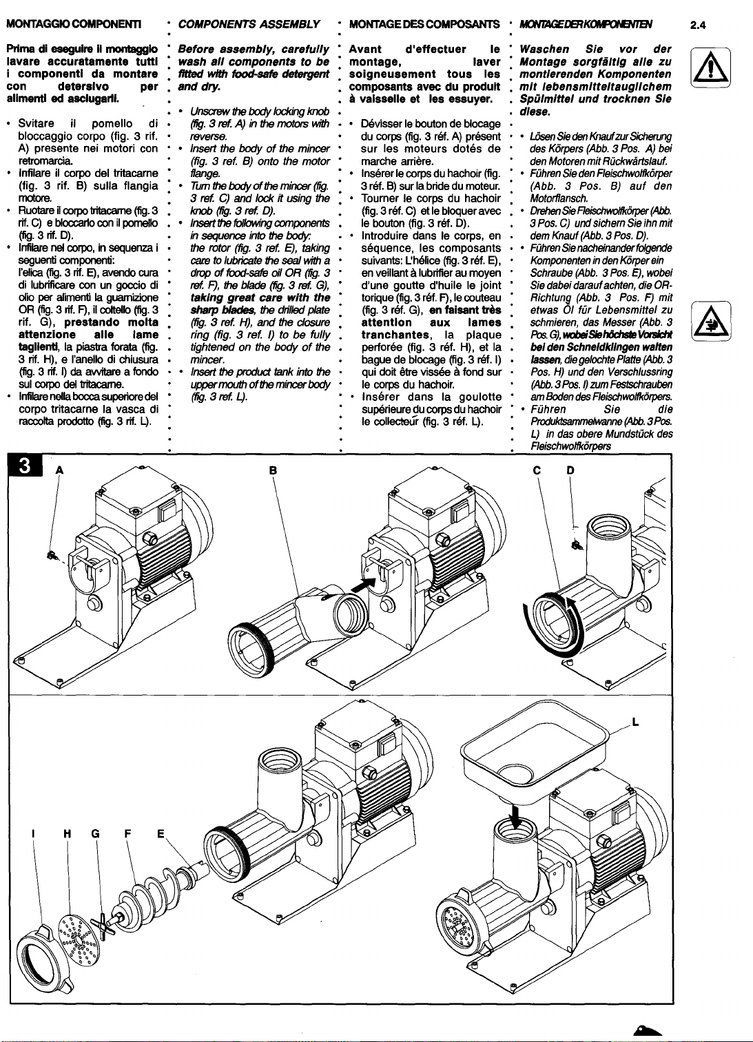
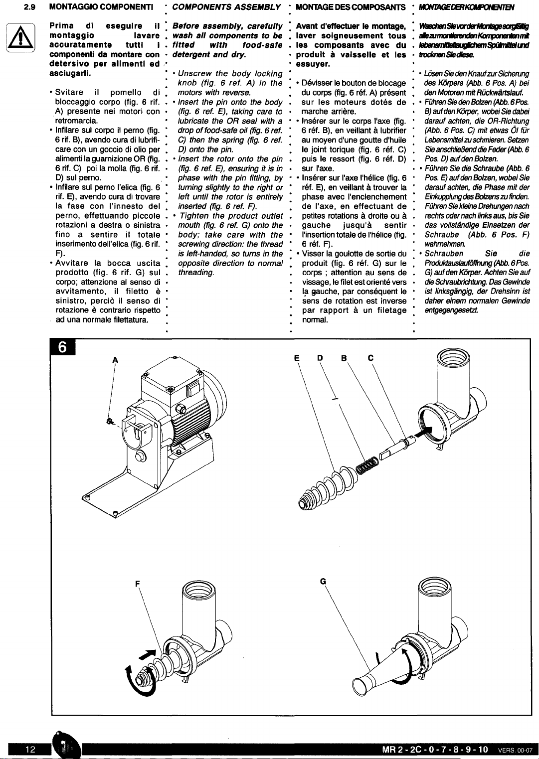
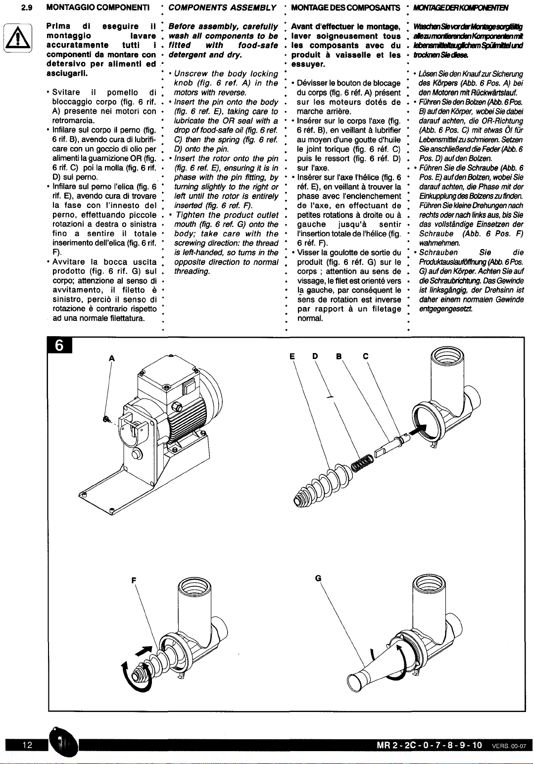
Prima dl eseguire II
montaggio lavare
accuratamente tutti I
componentl da montare con
detersive per allmentl ed
asclugarll.
Before assembly carefully
wash all components to be
fitted with food-safe
• detergent and dry.
: Avant d effectuer Ie montage, :
W8IIl:tB JSleMl cirAtnllgeSQ9lillg
• laver solgneusement tous •
alezunJOl.81mIKDntDrenlllnd
• les composants avec du • 1ebeIJSt/ille/la"g'c1Jem~1IJd
• produit
ill
vaisselle et les •
tIOc1aJenSledlese.
• essuyer.
• Svitare il pomello di
bloccaggio corpo (fig. 6 rif.
A) presente nei motori con
retromarcia.
• Infilare sui corpo il perno (fig.
6 rif. B), avendo cura di lubrifi-
care con un goccio di olio per
alimentilaguarnizioneOR (fig.
6 rif. C) poi la molla (fig.6 rif.
0) sui perno.
• Infilare sui perno I'elica (fig. 6
rif. E), avendo cura di trovare
la fase con I'innesto del
perno, effettuando piccole
rotazioni a destra
0
sinistra
fino a sentire il totale
inserimentodell'elica (fig. 6 rif.
F).
• Avvitare la bocca uscita
prodotto (fig. 6 rif. G) sui
corpo; attenzione al senso di
avvitamento, il filetto e
sinistro, perch) il senso di
rotazione e contrario rispetto
ad una normale filettatura.
• Unscrew the body locking •• L6senSiedenKnaufzurSicherung
knob (fig.
6
ref.
A)
in the •
OevisserIeboutonde blocage:
des Korpers (Abb.
6
Pas.
A)
bei
motors with reverse.
du corps (fig.6 ref.A) present.
denMotorenmitRiickwartslauf.
• Insert the pin onto the body
sur les moteurs dotes de ••
FiihrenSiedenBolzen(Abb.6Pos.
(fig.
6
ref. E), taking care to
marche arriere.
8)aufdenKorper, wobeiSiedabei
lubricate the OR seal with
a • Inserer sur Ie corps I'axe (fig.
darauf aehten, die OR-Richtung
drop offood-safe oil (fig.
6
ref.
6 ref. B), en veillant ill lubrifier
(Abb.
6
Pas.
C)
mit etwas 01 fUr
C)
then the spring (fig.
6
ref.
au moyen d'une goutte d'huile
Lebensmittelzuschmieren.Setzen
0)
onto the pin.
Ie joint torique (fig. 6 ref. C)
SieanschlieBenddieFeder(Abb.
6
• Insert the rotor onto the pin
puis Ie ressort (fig. 6 ref. 0)
Pas.
0)
aufdenBalzen.
(fig.
6
ref. E), ensuring it is in·
sur I'axe. • •
Fiihren Siedie Schraube (Abb. 6
phase with the pin fitting, by ••
Inserer sur I'axe I'helice (fig. 6'
Pas.E)aufdenBalzen, wobeiSie
turning slightly to the right or
ref. E), en veillant illtrouver la
darauf aehten,die Phase mit der
left until the rotor is entirely'
phase avec I'enclenchement
EinkuppiungdesBolzenszufinden.
inserted (fig.
6
ref. F).
de I'axe, en effectuant de
FiihrenSiekleineOrehungennach
• Tighten the product outlet
petites rotations ill droite ou ill
rechtsodernachlinksaus, bisSie
mouth (fig.
6
ref.
G)
onto the
gauche jusqu'ilI sentir
das vol/standige Einsetzen der
body; take care with the
I'insertiontotale de I'helice(fig.
Sehraube (Abb.
6
Pas. F)
screwing direction: the thread
6 ref. F).
wahmehmen.
is left-handed,
so
turns in the •
Visser la goulotte de sortie du • •
Sehrauben Sie die
opposite direction to normal
produit (fig. 6 ref. G) sur Ie'
ProduktausJaufOffnung(Abb.6Pos.
threading.
corps ; attention au sens de G)
aufdenKorper.Achten Sieauf
vissage,Iefilet estorientevers
dieSchraubrichtung.OasGewinde
la gauche, par consequent Ie
ist linksgangig, der Orehsinn ist
sens de rotation est inverse
daher einem normalen Gewinde
par rapport ill un filetage
entgegengesetzt.
normal.
-,

• Infilare il gruppo spremi • Insert the tomato press unit
pomodoro sulla flangia del into the motor flange, turning
motore, effettuando la and then locking with the
rotazione, poi bloccarla con i1. knob (fig. 7ref. A).
pomello (fig. 7 rif.A). • • Fit the product chute (fig. 7
• Montare 10 scivolo ref. B) under the mouth,
convogliatore prodotto (fig. 7. locking it with the respective •
rif. B) sotto la bocca,. fastenings (fig. 7ref. C).
bloccandolo con i rispettivi • Tighten the product tank (fig.
agganci (fig. 7 rif. C). 7 ref. 0) over the upper hole
• Awitare lavascaprodotto(fig. in the tomato press body.
7 rif. D) sui foro superiore del
corpo dello spremipomodoro. •
• • Fuhren Sie die
Tomatenpressgruppeauf den
Motorflansch und sichern Sie
mitdemKnauf(Abb.
7
Pos.A).
• Montieren Sie die
ProduktfOrderrutsche(Abb. 7
Pos. B) unterdas Mundstiickund
sichem
Siemitden
zugehOrigen
Einhakvorrichtungen (Abb. 7
Pos. C).
• Schrauben Sie die
• Produktwanne (Abb.
7
Pos.
0) auf die obere 6ffnung des
Tomatenpresskorpers.
• Mettre en place Ie groupe
presse-tomatesur la bride du
moteur, en effectuant la
rotation, puis la bloquer avec
Ie bouton (fig. 7 ref. A).
• Monter Ie dispositif d'amenee
du produit (fig. 7 ref. B) sous •
lagoulotte,enIebloquantavec
les fixations (fig. 7 ref. C).
• Visser Ie collecteur (fig. 7 ref. •
D) sur I'orifice superieur du
corps du presse-tomate.

• Accertarsi che I'alimentazione
elettricadelia rete corrisponda
a quella richiesta dalla
macchina e riportata sulla
targhetta del motore.
• Infilare la spina nella presa di
alimentazioneenergiaelettrica.
• Versareipomodoridalavorare
nella vasca.
• Posizionare sotto la bocca di
uscita del filtro un recipiente
per alimenti per la raccolta
degli scarti delia lavorazione
• Posizionare sotto 10scivolo di
uscita un recipiente per
alimenti per la raccolta del
succo di pomodoro
• Accendere la macchina con
I'interruttore in posizione "I".
• Prestare attenzione
all'eventuale giro avuoto delle
spremipomodorocheall'awio
del motore tende a bloccarsi
• Infilareipomodorinelforodelia
vasca utilizzando
esclusivamente il pestello in
dotazione.
• • Ensure that the mains power
supply matches that required
by the machine, indicated on
the motor plate.
• Connect the plug to the mains
power supply.
• Pour the tomatoes to be
processed into the tank.
• Place
a
food container under
the outlet mouth of the filter to
collect the waste.
• Place
a
food container under
the outlet chute to collect the
tomato juice.
• Press the switch to position
"/" to switch on the machine.
• Ensure the tomato press does
not run empty to prevent the
motor stalling.
• Guide the tomatoes into the
tank hole using only the
supplied pusher.
: • S'assurer que I'alimentation
electrique du reseau
correspond
a
celie requise par
I'appareil et indiquee sur la
• plaquedu moteur.
• • Introduirela fichedans la prise
d'alimentationelectrique.
• • Verser les tomates
a
presser
: dans la cuve.
• • Placer sous la goulotte de
sortie du filtre un recipient
pour aliments pour la
recuperation des dechets de
• production
• • Placer sous la glissiere de
sortie un recipient pour
aliments pour la recuperation
• du jus de tomate
• • Allumer la machine avec
I'interrupteuren position "I".
• • Faireattention
a
I'eventueltour
a
vide du presse-tomate qui,
au demarrage du moteur, a
tendance
a
se bloquer
• • Introduire les tomates dans
I'orificede la cuve en utilisant
exclusivement Ie pilon fourni
avec I'appareil.
• Stellen Sie sicher,
dass
die
elektrischeStromversorgungdem
vonderMaschinegefordertenund
auf dem Typenschilddes Motors
angegebenenWertentspricht.
• Fiihren Sie den Stecker in die
Steckdose.
• Geben Sie die zu verarbeitenden
Tomatenindie Wanne.
• PositionierenSieeinenBehalterfUr
Lebensmitte/ zur Aufnahme des
Verarbeitungsabfalls unter der
Filterausgangsoffnung.
• PositionierenSieeinenBeMlter fUr
Lebensmittel zur Aufnahme des
Tomatensafts unter der
Aus/aufrutsche.
• SchaltenSiedieMaschinemitdem
SchalterinderPosition"/"ein.
• AchtenSiedarauf,gegebenenfalls
eine Leerumdrehung der
Tomatenpresseauszufiihren, da
diesebeimAn/auf
des
Motorsdazu
tendiertzu b/ockieren.
• Geben Sie die Tomaten in die
6ffnungderWanne.VerwendenSie
dazu ausschlieBlich den
mitgeliefertenStoBel.

Nei motori con potenza di 0,7 HP
o superiore,
e
possibile la
rotazione del motore in senso
contrario per effettuare tentativi
di sbloccaggio rotazione:
premere I'interruttore in posizione
"II" solo per 2
0
3 impulsi,
dopodiche, se I'inconveniente
persiste, si deve smontare iI
gruppo spremi pomodoro.
SMONTAGGIO GRUPPO
SPREMI POMODORO
Sfilare la vasca raccolta
prodotto, prestando
attenzione che se si sono
utllizzati del pomodori bollitl,
potrebbe essere calda e
causare piccole ustioni.
Stessa precauzione si deve
adottare per
10
smontaggio
degli altri componenti.
Per
10
smontaggio del gruppo
spremi pomodoro si deve
utilizzare I'apposita chiave in
dotazione (fig. 9 rif. A). Prestare
attenzione al senso di rotazione
delia bocca che presenta un
filetto sinistro, percib iI senso di
rotazione
e
contrario rispetto ad •
una normale filettatura.
• Sur las moteurs d'une puissance
• de 0,7 HP ou plus, iI est possible
de commander la rotation du
moteur dans Ie sens inverse pour
effectuer des tentatives de
deblocage de la rotation: Enfoncer
I'interrupteuren position "II"pas plus
de 2 ou 3 fois. Si I'inconvenient
devait persister, iIfaut demonter Ie
groupe presse-tomate.
TOMATO
DISASSEMBL Y PRESS DEMONTAGE DU GROUPE
PRESSE·TOMATE
BeidenMotorenmiteinerLeistungvon
0,7
HP oder dBJijberist dieDrehung
desMotorsim
entgegengesetzt
Sinn
moglich um zu versuchen, die
Drehbewegung wieder freizugeben:
DnJckenSiedenMotornurfUr20der 3
Impulsein die Position"II". Solltedie
Storung dann nicht behoben sein,
montieren Siedie TomatenpressgnJppe
an
AUSBAU DER
TOMATENPRESSGRUPPE
ZiehenSiedieProduktsammelwa
henlus, wobeiSiedaraufachten, dass
dlesebeiderVenvendunggekocht1N
Tomaten heiB sein und leichte
Verbrennungen verursachen
kiimtBn.
Dieselbe VorsichtsmaBnahme ist
beim Ausbau der anderen
Kon¥JoII6IienanzuMenden.
Zum Ausbau der
Tomatenpressgruppe ist der
mitgelieferte Schliissel (Abb. 9
Pos.
A)
zu verwenden. Achten Sie
auf die Drehrichtung der Offnung.
Das Gewinde ist linksgangig, der
Drehsinn ist daher einem normalen
Gewinde entgegengesetzt.
EnleverIecollecteurenfaisant
• attention au fait que, sl I'on a
: utllise des tomates boulllles,
iI pourrait etre chaud et
causerde petites brulures. La
meme precaution doit etre
adoptee pour Ie demontage
des autres caoll1posants.
Pour Ie demontage du groupe
presse-tomate, iI faut utiliser la
clef prevue
a
cet effet fournie
avec I'appareil (fig. 9 ref. A).
Faire attention au sens de
rotation de la goulotte qui
presente un filetage oriente vers
la gauche, si bien que Ie sens
• de rotation est inverse par
rapport
a
un filetage normal.
Motors with
0 7
HP or higher may
be run in the opposite direction
to attempt to ciear the jam:
press the switch to position "II" 2
or
3
times only; then, if the
problem persists, the tomato
press unit must be dismantled.
Remove the product tank,
using caution as boiled
tomatoes may be hot and
cause scalding.
The same precaution is to be
taken when disassembling
the other components.
To
disassemble the tomato
press unit, use the wrench
• supplied (fig.
9
ref. A). Take
care with the mouth rotation
direction, which has aleft-
handed thread, so turns in the
opposite direction to normal
threading.

Ad ogni modello TC,
e
possibile
applicare i componenti per la
trasformazione in insaccatrice.
1) Imbuto insaccatore
2) Ferma elica
Prima di esegulre II
montagglo lavare
accuratamente tutti i
componentl da montare con
deterslvo per alimenti ed
asclugarli.
• Montare il corpo e I'elica del
gruppo tritacarne (fig. 11 rif. A).
• Montare il ferma elica (fig. 11
rif. B) infilandolo sui perno
dell'elica.
• Appoggiare I'imbuto (fig. 11 rif.
C) al corpo e bloccarlo con la
ghiera (fig. 11 rif. D).
BAGGING MACHINE
CONFIGURATION
It is possible to apply
components to each TC model
to convert to abagging
machine.
1) Bagging funnel
: 2)
Rotor stop
• CONFIGURATION MACHINE
: ASAUCISSE
·
• Sur
d"1c:QJe
Il"lOd9le
TC.
i
est possible
• d'appliquer las composants pour Ia
• transformation en machine
a
: saucisse
KONFIGURATION DER
EINSACKMASCHINE
Beinjedem Modell TC besteht die
M6glichkeit, die Komponenten
• zur Umformung in eine
Einsackmaschine einzusetzen.
• A V E R TIS 5 E MEN T 5 • MONTAGEHINWEISE
CONCERNANT LE MONTAGE
• 1) Entonnoir machine
a
saucisse
1)
Einsacktrichter
: 2) Blocage helice :
2)
Schrauben
COMPONENTS ASSEMBLY' MONTAGEDESCOMPOSANTS • MONTAGE
KOMPONENTEN
Before assembly, carefully
wash all components to be
fitted with food-safe
detergent and dry.
• Fit the body and rotor of the
mincer unit (fig.
11
ref. A).
• Fit the rotor stop (fig. 11ref. B)
inserting it onto the rotor pin.
• Rest the funnel (fig. 11 ref. C)
on the body and lock it with the
ring nut (fig.
11
ref. 0).
:. Avant d'effectuerIe montage,
laver solgneusement tous
les composants avec du
produit
a
valsselle et les
essuyer.
• Monter Ie corps et I'helice du
groupe hachoir (fig. 11 ref. A).
• Tourner la bague de blocage
de I'helice (fig. 11 ref. B) en
I'enfilant sur I'axe de I'helice.
• Poser I'entonnoir (fig. 11 ref.
C) au corps et Ie bloquer avec
la bague (fig. 11 ref. D).
Waschen Sie vor der
Montage sorgfaltig aile zu
• mont/erenden Komponenten
: m/t lebensmitteltauglichem
Spii/mittel und trocknen S/e
• diese.
• Montieren Sie K6rper und
Schraube der Reischwolfgruppe
(Abb.
11
Pas. A).
• Montieren Sie die
Schraubensicherung (Abb. 11
Pos. B), indem Sie diese aufden
Balzen der Schraube fiihren.
• 5etzen Sie den Trichter (Abb. 11
Pos. C) an den K6rper und
blockieren ihn mit dem
Sicherungsring (Abb.
11
Pas. 0).

Ad ogni modello TC,
e
possibile
applicare i componenti per la
trasformazione in insaccatrice.
1) Imbuto insaccatore
2) Ferma elica
Prima di esegulre II
montagglo lavare
accuratamente tutti i
componentl da montare con
deterslvo per alimenti ed
asclugarll.
• Montare il corpo e I'elica del
gruppo tritacarne (fig. 11 rif. A).
• Montare il ferma elica (fig. 11
rif. B) infilandolo sui perno
dell'elica.
• Appoggiare I'imbuto (fig. 11 rif.
C) al corpo e bloccarlo con la
ghiera (fig. 11 rif. D).
BAGGING MACHINE
CONFIGURATION
It is possible to apply
components to each TC model
to convert to abagging
machine.
1) Bagging funnel
: 2)
Rotor stop
• CONFIGURATION MACHINE
: ASAUCISSE
·
• Sur
d'1i:QJe
Il"lOd6te
TC,I est possible
• d'appliquer las composants pour Ia
• transformation en machine
a
: saucisse
KONFIGURATION DER
EINSACKMASCHINE
Bein jedem Modell TC besteht die
M6glichkeit, die Komponenten
• zur Umformung in eine
Einsackmaschine einzusetzen.
• A V E R TIS 5 E MEN T 5 • MONTAGEHINWEISE
CONCERNANT LE MONTAGE
• 1) Entonnoir machine
a
saucisse
1)
Einsacktrichter
: 2) Blocage helice :
2)
Schrauben
COMPONENTS ASSEMBLY MONTAGEDESCOMPOSANTS' MONTAGE
KOMPONENTEN
Before assembly, carefully
wash all components to be
fitted with food-safe
detergent and dry.
• Fit the body and rotor of the
mincer unit (fig.
11
ref. A).
• Fit the rotor stop (fig. 11ref. B)
inserting it onto the rotor pin.
• Rest the funnel (fig. 11 ref. C)
on the body and lock it with the
ring nut (fig.
11
ref. 0).
:. Avant d'effectuerIe montage,
laver solgneusement tous
les composants avec du
produit
a
valsselle et les
essuyer.
• Monter Ie corps et I'helice du
groupe hachoir (fig. 11 ref. A).
• Tourner la bague de blocage
de I'helice (fig. 11 ref. B) en
I'enfilant sur I'axe de I'helice.
• Poser I'entonnoir (fig. 11 ref.
C) au corps et Ie bloquer avec
la bague (fig. 11 ref. D).
Waschen Sie vor der
Montage sorgfiiltig aile
zu
• mont/erenden Komponenten
: m/t lebensmitteltauglichem
Spii/mittel und trocknen S/e
• diese.
• Montieren Sie K6rper und
Schraube der Reischwolfgruppe
(Abb.
11
Pos. A).
• Montieren Sie die
Schraubensicherung (Abb. 11
Pos. B), indem Sie diese aufden
Bolzen der Schraube fiihren.
• 5etzen Sie den Trichter (Abb. 11
Pos. C) an den K6rper und
blockieren ihn mit dem
Sicherungsring (Abb.
11
Pos. 0).
This manual suits for next models
6
Other FABIO LEONARDI Kitchen Appliance manuals
Popular Kitchen Appliance manuals by other brands

Lakeland
Lakeland My Kitchen 13665 user manual

Maxwell
Maxwell MW-3804 W Manual instruction

TEFAL
TEFAL cook4me operating instructions

Fisher & Paykel
Fisher & Paykel ELBA OR90 Series Installation instructions and user guide

Bonnet
Bonnet OPTIMUM 700 Instructions for use

Cookworks
Cookworks HB956SH6PB Care & instruction manual