Fabtech Crossover Extensible Knee User manual

Crossover™ Manual V1/62920016 ©Fabtech Systems LLC. All Rights Reserved.
Crossover™ Extensible Knee
“Infinite Possibilities”
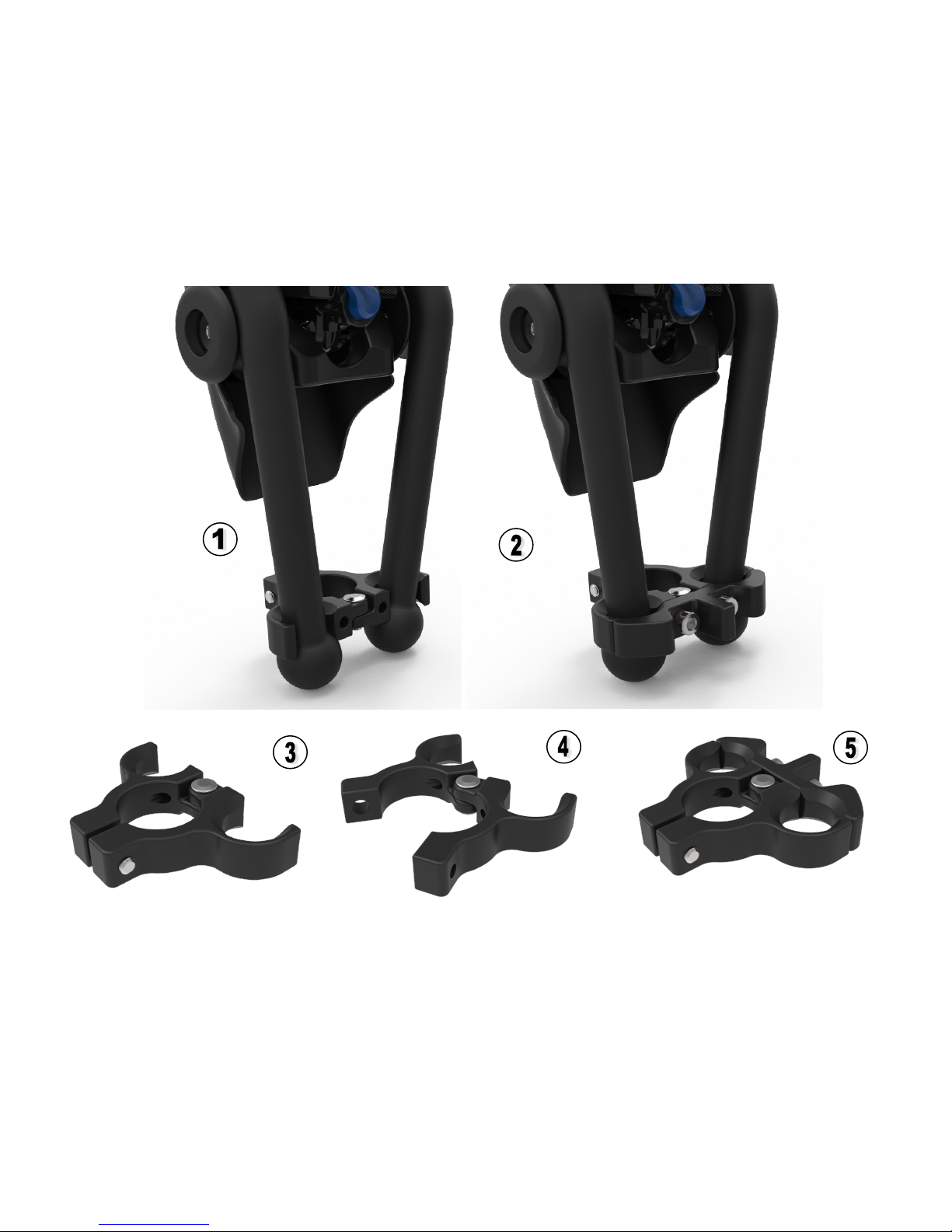
Congratulations on your decision to purchase a Crossover™ Extensible Knee! We have taken our original
Bartlett Tendon Knee (BTK) design and made it even better! The new Crossover™ is an ambulatory Extensi-
ble knee that transforms into a sports knee in less than three minutes!
This state-of-the-art prosthetic knee system will be very gratifying if you service and maintain it accordingly.
Please enter the serial numbers of your knee below. You will provide this number if the knee unit requires
servicing. Serial numbers are located on the knee frame under the protective cover.
This owner's manual contains the latest information for this model (as of June 2016). Future minor differ-
ences due to developments in the knee design cannot be ruled out completely.
All specifications are non-binding. LEFTSIDE Industries (Leftside) specifically reserves the right to modify or
delete technical specifications, prices, colors, forms, materials, services, designs, equipment, etc., without
prior notice and without specifying reasons, to adapt these to local conditions, as well as to stop production of
a particular model without prior notice. Leftside accepts no liability for delivery options, deviations from illus-
trations and descriptions, as well as misprints and other errors. The models portrayed (via included illustra-
tions) partly contain special equipment that does not form part of the regular scope of delivery.
Reproduction, even in part, as well as copying of all kinds, is permitted only with the express written permis-
sion of the copyright owner.

Crossover™ Manual V1/62920016 ©Fabtech Systems LLC. All Rights Reserved.
1. Multidurometer impact/kneeling pads
2. ABS protective cover
3. ABS protective X/CAM™ covers
4. Rubber socket flexion limiters
5. Urethane lower frame bumpers
6. Easy to access “On Demand” shock controls
7. RT3 pneumatic/hydraulic shock
Crossover™ Knee Walking Configuration

Crossover™ Manual V1/62920016 ©Fabtech Systems LLC. All Rights Reserved.
1. X/CLIP™ removable composite tendon connectors
2. Urethane tendons
3. X/CAM™ 3 position guide wheels
4. Urethane lower tendon guide wheels
5. Lower tendon retaining clamp
6. Multidurometer impact/kneeling pads
7. ABS protective cover system
8. SS removable X/CAM™ locking pin
9. Rubber socket flexion limiters
10. RT3 pneumatic/hydraulic shock
11. Tendon lock plate
Crossover™ Knee Sport Configuration

Crossover™ Manual V1/62920016 ©Fabtech Systems LLC. All Rights Reserved.
Crossover ™ Knee Parts
1. Multidurometer impact/kneeling pads
2. Urethane lower tendon guide wheels
3. Urethane lower frame bumpers
4. X/CAM™ 3 position guide wheels
5. Lower tendon retaining clamp
6. Urethane tendons
7. X/CLIP™ removable composite tendon connectors
8. RT3 shock pump
9. ABS X/CAM™ cover
10. ABS protective cover, knee frame
11. RT3 pneumatic/hydraulic shock

Crossover™ Manual V1/62920016 ©Fabtech Systems LLC. All Rights Reserved.
Crossflex™ Preflexion Wedges
1. 20° Crossflex™ wedge
2. 30° Crossflex™ wedge
3. 40° Crossflex™ wedge
When installing Crossflex™ preflexion wedges, take care as to not tear the foam
section that locks into the knee unit.
Note: For instructional video visit www.leftsideindustries.com

Crossover™ Manual V1/62920016 ©Fabtech Systems LLC. All Rights Reserved.
Lower Tendon Connector
1. Placement of tendons into lower connector
2. Back locking plate attached to connector
3. Lower tendon connector
4. Lower tendon connector in open position
5. Lower tendon connector in closed position with locking plate

Crossover™ Manual V1/62920016 ©Fabtech Systems LLC. All Rights Reserved.
General Knee Description 1
Design Features & Function 1
Crossover™ Knee Kit Contents 2
Compatible Activities, Sports and Rehabilitation 3
New Features and Benefits 4
Technical Specifications 4
Understanding the Crossover™ Knee System 5
Ambulation Configuration 5
Sport Configuration 5
How the Systems Work Together 6-8
Tendons 6
Upper Tendon Connectors 6
Lower Tendon Connector 7
X/CAM™ Guide Wheels 7
RT3 Shock 8
Crossflex™ Preflexion Wedges 8
“VED” Variable Extension Dampening System 8
Alignment and Initial Ambulation Settings 9-14
Alignment and First Time Knee Set Up 10
Understanding Shock Controls 11-12
Walking the Patient and Adjusting the Shock 13-14
Sports Set Up 15-17
X/CAMs™ 15
Lower Tendon Guide Rollers 15
Lower Tendon Retaining Connector 16
X/CLIP™ Upper Tendon Connectors 16
Tendons Set Up 17
Crossflex™ Preflexion Wedges Set Up 17
Baseline Activity Recommendations Chart 18-20
Knee Maintenance 20-22
Warranty 23-24
Service Contact Information 25
Technical Support Contact 25
L-Code Information 25
Component Options and Creative Solutions 25
Set Up Reference Notes 26
Parts List 26
X/CLIP™ Mounting Template 27
Table of Contents

Crossover™ Manual V1/62920016 ©Fabtech Systems LLC. All Rights Reserved.
General Knee Description
Designed exclusively for lower limb prosthetic fittings, the Crossover™ knee is a monocentric (single axis)
articulated Extensible knee that can be used for general ambulation or—with simple additions/adjustments—
can be used for high activity sports. Designed similar to the Mauch S-N-S knee unit, the Crossover™ knee
has the advantage of having the ability to add a patented highly adjustable Tendon and Three-Position X/
CAM™ system when the user wants to participate in high activity sports or other activities.
Design Features & Function
Single-axis pneumatic/hydraulic knee system with swing and stance control adjustments
Designed for multispeed ambulation and sport activities
Adjustable Variable Extension Dampening “VED” bumper system (kneeling and impact)
Multi-faceted mode selector to control flexion and extension
Patented urethane tendon and Three (3) Position X/CAM™ system, offering infinite tunable resistance
and return in a removable Extensible format
Crossflex™ preflexion foam wedges for sport activities. Three pack kit comes in 20°, 30° and 40° degree
wedge settings
Removable ABS protective impact cover
Ultra lightweight CNC machined 6061-T aircraft aluminum frame with stainless steel inserts
Oilite™ self-lubricating bushings:
No maintenance with increased durability
Smooth motion in light use or heavy impact situations
Reduced play
All parts serviceable
Water and salt water resistant
1

Crossover™ Manual V1/62920016 ©Fabtech Systems LLC. All Rights Reserved.
Crossover™ Kit Contents
The Crossover knee kit comes with everything you will need to get your patient up and walking and participat-
ing in sports or other high activities.
Kit Contents: (PN: 1001-3)
Crossover™ Knee with 75 durometer Variable Extension Dampening “VED” bumpers (upper/
lower)
Protective ABS impact covers with X/CAM™ covers
Shock pump
2 pair urethane tendons
X/CLIPs™ with removable hardware
Easy hinged lower tendon clamp with locking system
6061-T CNC three (3) position X/CAMs™ with removable hardware
2 pair urethane lower frame tendon guide wheels for sport configuration
2 pair urethane lower frame bumper stops for ambulation configuration
Tendon connector placement template
User manual
Note: Consumable Products: The following items are classified as “Consumable Products” and will require
replacement when visual wear, cracks or tears are present. See “Periodic Maintenance Table” (Pages 20-22)
Urethane tendons
“VED” dampening bumpers
Protective cover
Crossflex™ inter-changeable preflexion wedges
Note: Available additional items NOT included in the Crossover™ kit:
Crossflex™ adjustable preflexion wedges are available for purchase in a three (3) pack kit
(PN: C113)
85 durometer “VED” bumper set
2

Crossover™ Manual V1/62920016 ©Fabtech Systems LLC. All Rights Reserved.
Ambulation
Walking and community ambulation.
Winter Sports
Alpine skiing
Telemark skiing
Cross country skiing
Snowboarding
Snow shoeing
Ice Skating
Hockey
Snow kiting
Water Sports
Water skiing
Wakeboarding
Wind surfing
Surfing
SUP
Kite boarding
Scuba diving
Rowing / crewing
Swimming
Summer Sports
Mountain biking
Road cycling
Skate boarding
Inline skating
Backpacking
Fighting sports
Hiking
Golf
Beach days
Moto Sports
Moto-cross
Enduro and trail
Motorcycle ADV
Snowmobile
Rehabilitation
Build muscle
Weight lifting / squatting
Promote general fitness
Increase active, quality time with family
Compatible Activities, Sports and Rehabilitation
3

Crossover™ Manual V1/62920016 ©Fabtech Systems LLC. All Rights Reserved.
New Features and Benefits
8° - 140° expanded range of USABLE flexion
No fade after 90° degrees flexion
New compact, lighter, stronger and 5cm (2”) shorter frame
Easy removable hinged lower tendon connector with lock (no need to remove feet)
ABS impact covers for sport and ambulation
Multi-durometer Variable Extension Dampening “VED” bumper system
Kneeling pad
3ea Crossflex™ adjustable pre-flexion position wedges
Oilite™ bushings that require no service
Demo/trial program
Technical Specifications
Maximum weight 125kg (275lbs)
Net weight 908g (2lbs)
Frame size 20cm (8 inches)
8° to 150° knee flexion available range
4

Crossover™ Manual V1/62920016 ©Fabtech Systems LLC. All Rights Reserved.
Understanding the Crossover™ Knee System
Ambulation Configuration
In the ambulation configuration the Crossover™ knee functions like a monocentric (single axis) S-N-S
knee unit, with a free swing feature utilizing a pneumatic/hydraulic shock with micro adjustment capabili-
ties and a unique “VED” impact multi-durometer inter-changeable bumper system to address swing and
stance gait phases.
Under normal ambulation conditions no tendons and X/CAMs™ are used. However, the tendon and X/
CAM™ system may be used for highly active walking situations like—for example—back packing or hik-
ing.
The Crossover™ knee utilizes a highly adjustable pneumatic/hydraulic cylinder to control flexion and ex-
tension adjustments.
Variable Extension Dampening “VED” bumper system is also used to address stance phase.
Sport Configuration
In the sport configuration the Crossover™ knee functions the same as in the ambulation noted above.
But, when combined with the relatively linear spring rate of the tendons and X/CAM™ system the Crosso-
ver™ delivers a smooth even energy absorption and return. It is this smooth isotonic stability that makes
the Crossover™ knee such a good choice for rehab and sport applications.
Under sporting conditions, the tendon and X/CAM™ system are generally used. This system takes a user
about 3 minutes to add to the knee.
Crossflex™ adjustable preflexion wedges may also be used to position the user into a more preflexed po-
sition. For example, snowboarding uses a 30° preflexion position.
In general more air is added to the shock during heavy sport activities in combination with the tendon and
X/CAM™ system.
Ambulation Sport
5

Crossover™ Manual V1/62920016 ©Fabtech Systems LLC. All Rights Reserved.
Tendons
The tendon system is the heart of the Crossover™ knee, offering a highly var-
iable and infinitely tunable resistance and return mechanism. This relatively
linear spring rate of tendons and X/CAM™ system delivers a smooth, even
energy absorption and return. This patented tendon and X/CAM™ system is
what makes it possible for the user to get extension/resistance moments that
provide the needed assistance to enable exiting and absorbing the extreme
flexion moments associated with sport activities.
This system is comprised of four primary components: tendons, tendon
connectors, three (3) position X/CAM™ guide wheels, and lower tendon
connector.
Only one tendon durometer is needed with the Crossover™ knee.
One OR two tendons may be used at a time.
The primary goal in setting selections is to find the winning combination
that provides the optimal flexion resistance and extension assistance that
will balance forces like a natural leg for the activity the user is doing. The
idea is: “helping, but not hindering.”
Upper Tendon Connectors
The carbon tendon connectors form the proximal connection between the
socket and the tendon system. These connectors form the pocket that the flat-
tened ball end of the tendon slips into.
They are connected with removable hardware or they can be bonded to
the socket.
Optimal location is between 5” to 9” proximal of knee center.
Ensure the tendon has a clear path on the socket to the tendon guide
wheel.
How the Systems Work Together
6

Crossover™ Manual V1/62920016 ©Fabtech Systems LLC. All Rights Reserved.
Lower Tendon Connector
The lower tendon connector is the distal attachment point for the ball
end of the tendon.
This connector can slide up or down the pylon, and is used as addition-
al adjustment for the tendons sliding distally to increase tension and
proximally to reduce tension. The lower connector that comes in the kit
is a designed to fit a 30mm pylon and is hinged for easy on and off.
X/CAM™ Guide Wheels
To enhance the fluid dynamic feel of the tendons a three (3) position
tendon X/CAM™ Guide Wheel system is used in conjunction with the
tendons at the knee axis. These X/CAMs™ allow the highest tuning of
tendon response within further progression of knee flexion.
Having a tendon resistance properly tuned within a specific range of
flexion is very important as it means the user can tune specific points
in flexion for the tendon to CAM into action, offering additional support
where it’s need it, or X/CAM™ out the energy for explosive returns.
Because of this X/CAM™ action Crossover™ users also achieve
much lower preflexion resistance allowing them to conserve much
needed energy while still providing the power and support needed
flexing 25 degrees and beyond.
Each X/CAM™ offers three levels of progression and an additional 4th
non-pinned option on each side, and can be used with the Crosso-
ver™ tendons in singles or pairs. These selections offer an unsur-
passed series of options within the full range of flexion that can all be
done on-the-fly without tools. The X/CAMs™ can also be utilized in
reverse (4th option) or in a non-pinned free movement position deliver-
ing the identical performance of the previous BTK model with a round
guide wheel.
Pos.1 (single dot): This position is suggested for the least amount of X/
CAM™ effect with knee flexion (least amount of resistance).
Pos.2 (two dots): This position is suggested for a mid-range of X/CAM™
effect with knee flexion (middle range of resistance).
Pos.3 (three dots): This position is suggested for a maximum X/CAM™
effect with knee flexion (maximum range of resistance).
Pos.4 (no locking pin): In this position the X/CAM™ is in a FREE motion
state with no increased resistance. This position is suggested if the
amount of flexion tension with the tendon is desired in the very least
amount of tension as the X/CAM™ will not engage during knee flexion.
7

Crossover™ Manual V1/62920016 ©Fabtech Systems LLC. All Rights Reserved.
RT3 Shock
The Crossover™ knee utilizes a pneumatic/hydraulic shock. This
shock uses a combination of air, oil and valving to control and change
flexion and extension moments. Air pressure is user adjustable and
the regulated air spring/air pressure will dictate how firm that spring is.
The user controls will regulate flexion and extension rates.
Similar in function to the S-N-S Mauch units this pneumatic/hydraulic
shock provides the ability to manage average ambulation require-
ments, and when combined with the tendon, X/CAM™ and Cross-
flex™ wedges (see below), provides the additional dampening and
rebound for high activity sports.
Crossflex™ Wedges
Crossflex™ preflexion wedges are a mid-durometer foam wedge sys-
tem that is user added to change the preflexion angle/position per
sport activity. Different sports require different preflexion settings.
Snowboarding for example may require 30° whereas mountain biking
may do better at 10°.
Crossflex™ wedges are designed to act like knee cartilage and pro-
vide a small amount of compression absorption. This feature absorbs
a small percentage of impact energy keeping it from directly translating
into the prosthetic limb. The net result is a less stressed prosthetic
limb.
Crossflex™ wedges require no tools to add to the knee and are insert-
ed at the knee axis.
20, 30 and 40 degree angle/positions are available. Note: When
standing forces are placed on the wedges, there is an average com-
pression rate of 5 to 10% to the wedges.
Variable Extension Dampening “VED” Bumper System
VED bumpers come in 75° and 85° durometer ratings and can be in-
terchanged to address knee performance during stance phase. 85 du-
rometer VED pads can be ordered separately. ( Page 26)
8

Crossover™ Manual V1/62920016 ©Fabtech Systems LLC. All Rights Reserved.
Alignment and Initial Ambulation Settings
This procedure addresses both ambulation and sport
When setting up the Crossover™ knee for the first time on a new patient, the goal is to align the knee in a sta-
ble condition for ambulation. All adjustments to tune the knee are after the patient is set in a stable alignment.
Make sure the patient is in parallel bars for safety as the knee will be in free swing with no or very little re-
sistance in the initial set up phase.
1. Unpack the box and make sure all items are in the package.
2. Remove air cap on shock and remove any residual air pressure. Depress valve to remove air.
(Figure 1)
3. Set all shock settings to the zero position. (Page 11-12)
4. Remove protective covers for easy adjustments.
5. Attach Crossover™ to prosthetic.
6. For recommended beginning alignment. (Figure 2)
Warning! If the patient is not stable they can fall at this stage of the fitting.
Figure 1
Figure 2
9

Crossover™ Manual V1/62920016 ©Fabtech Systems LLC. All Rights Reserved.
Alignment & First Time Set-Up
The alignment reference line is equal to the weight line
1. Alignment Reference Line (Socket Bisection)
2. Knee Axis Reference Point
•Establish a vertical pylon.
•Establish the knee center height.
•Establish the appropriate socket angles. 5 degrees of socket flexion is
recommended.
•Position the socket so that the alignment reference line bisects the
lateral wall at the ischial level of the socket and falls through or
slightly posterior to the knee axis.
•Establish the correct length of the prosthesis.
If the weight line is too far anterior to the knee axis, the knee may require much more effort to create a
hyperextension moment that will engage the knee axis and allow for fluid initiation of the knee flexion.
Premature knee flexion may result from a weight line position too posterior to the knee axis and will
make the knee unstable.
10
Figure 2 Figure 2/A
Figure 2/A displays alignment with a
socket flexed at10 degrees.

Crossover™ Manual V1/62920016 ©Fabtech Systems LLC. All Rights Reserved.
Understanding Shock Controls
Flexion Resistance—Blue Lever
This lever controls flexion, also known as “dampening” on this shock. The flexion lever has three positions.
Looking at the shock in the knee frame, these positions are 10, 2 and 6 O’clock.
On the shock these positions are labeled as the following: (Figure 3)
10 O’clock = Unlock
2 O’clock = Pedal
6 O’clock = Lock
Figure 3
Most common setting for ambulation:
10 O’clock position = Lowest flexion resistance. “Unlock” (Figure 4)
Additional settings most commonly used to address ambulation on un-
even terrain, stairs and steep declines:
2 O’clock position = Medium flexion resistance. “Pedal” (Figure 5)
6 O’clock position = Highest flexion resistance. “Lock”
(Figure 6)
Figure 4
Figure 6
Figure 5
Note: With higher air pressures the 6 O’clock setting can act as an on demand extension lock.
11

Crossover™ Manual V1/62920016 ©Fabtech Systems LLC. All Rights Reserved.
Extension Resistance—Red Dial
This red dial controls extension, also known as “rebound” on this shock. The red dial is located directly be-
hind the blue flexion lever. The red extension dial has a BLACK notch on it to indicate its position.(Figure
7)
The dial rebound adjuster has ten positions with audible/tactile clicks
Clockwise rotation = slow extension (rebound)
Counter-clockwise rotation = faster extension (rebound)
Air Pressure:
Air pressure influences flexion and extension based on the amount of air pressure added to the shock.
High air pressures create more resistance and are better for heavy impact sport.
Lower air pressures create less resistance and are better for walking.
You can run 1psi to 275psi depending on the user’s requirements and the activity.
Figure 7
12

Crossover™ Manual V1/62920016 ©Fabtech Systems LLC. All Rights Reserved.
Walking the Patient and Adjusting the Shock
Step 1.
Set the shock to the zero set point.
Set the Blue Lever to the 10 O’ Clock position.
Turn the Red Dial in a clockwise rotation until it stops.
Remove all the air from the shock.
Remove air cap and depress the valve with a tool.
Step 2.
Set shock to “Recommended Home Position.” This is your starting position for each change in air pres-
sure.
Blue Lever set to the 10 O’ Clock position.
Turn Red Dial (4) clicks counter clockwise. The black notch should be at the 7 O’ Clock posi-
tion.
Add 10 psi to the shock using the supplied shock pump.
Step 3.
With the knee set at “Home Position” have the patient walk a few times in the parallel bars.
They should feel a slight resistance in the shock. This is a good starting point for ambulation
tuning.
The first adjustment to address is extension. Adjust the red dial either COUNTER-
CLOCKWISE (faster extension) or CLOCKWISE (slower extension) from the original 7 O’clock
home position. Find the desired extension speed of the knee while walking the patient in the
parallel bars. Move the dial one click at a time faster or slower as it may only take one click
either way to find the desired settings.
The second adjustment should be to flexion by adjusting the Blue Lever into one of three posi-
tion options on the shock.
The patient should be at an air pressure range that they can walk with while the Blue Lever is
in the 10 O’clock position. (labeled as “Unlock” on the shock)
Warning! If the patient is not stable they can fall at this stage of the fitting.
Note: Keep notes on settings while working through adjustments. (Page 26)
13
Table of contents
Popular Medical Equipment manuals by other brands

Dimedico
Dimedico hairegen user manual

RaySafe
RaySafe i3 Installation & service manual

Bosch
Bosch PFP5230 operating instructions

Lowenstein Medical
Lowenstein Medical SOMNOvent auto-S Instructions for use

Eosera
Eosera EAR VIEW MD Faq

Cantel Medical
Cantel Medical MEDIVATORS 2-8-650HAN Hookup connection guide