FACHOWIEC WELDER FANTASY BI-PULSE 201 User manual

ORIGINAL INSTRUCTIONS
2019
MANUAL WELDING

Page 2 with 33Page 2 with 33Page 2 with 33Page 2 with 33
MANUAL - WELDER Fantasy PULSE BI-201
Before using this product, read all instructions
with understanding and keep it for future use
TABLE OF CONTENTS
SAFETY AND SYMBOLS 3
DESTINY 6
DESCRIPTION OF THE DEVICE 6
TECHNICAL DATA 6
CONNECTION - SET polarity WELDING 7
WELDING PROCESS MIG / MAG 10
OPERATION WELDER FANTASY PULSE BI-201 12
Current Issues HANDLING EQUIPMENT 27
ELECTRICAL DIAGRAM 29
DEKLARACKA CONFORMITY thirty
WARRANTY CARD 31
Clause:
Despite making every effort to ensure that the information contained in this manual was complete and in accordance
with the actual situation, the company PROFESSIONAL FHW Zenon Świętek shall not be liable for any errors or
omissions. We reserve the right to change the specifications of the products described at any time without prior notice.

Page 3 with 33Page 3 with 33Page 3 with 33Page 3 with 33
MANUAL - WELDER Fantasy PULSE BI-201
1. SAFETY PRECAUTIONS SYMBOLS 1. SAFETY PRECAUTIONS SYMBOLS
It is essential to read these signs and safety precautions to protect the health and life of their own and other
people.
Read instructions before starting the machine. Use only original accessories supplied by
the manufacturer.
Some components may explode. Always use face shields and protective clothing with long
sleeves.
Static electricity can damage electronic components.
Use approved face shields and welding shields. Always use protective clothing designed for
welders. Metal splinters can injure your eyes. Always use safety glasses.
Electrical shock can result in death. Do not touch electrical components when the device is
connected to the power supply. Use dry and complete protective gloves and protective clothing.
Gases and vapors can be hazardous to health. During the process of extracting welding gases
and welding fumes. Inhalation of these substances can be dangerous to your health.
Eye protection welding filters. Depending on the current intensity, use shields with appropriate
filters.
Moving parts can cause injuries unit.
Too long continuous operation may cause overheating. Wait until the device cool down. Follow
the guidelines in the "efficiency and thermal protection."

Page 4 with 33Page 4 with 33Page 4 with 33Page 4 with 33
MANUAL - WELDER Fantasy PULSE BI-201
Damaged cylinders with technical gases can explode. The bottled gas is accumulated under high
pressure. Make sure the bottles are handled and stored in accordance with the requirements of
safety and fire.
Welded components could burn.
Wire protruding from the burner is sharp and can cause skin puncture.
Risk of fire and explosion. During welding work may lead to a fire. Welding station must be
separated and protected from flammable materials and explosives.
The magnetic field can disrupt the functioning of pacemakers. Before starting work, consult your
physician.
Do not weld at height without adequate protection.
Overturning or falling unit can cause serious injury.
• Before starting work, you must specify the place where the device is to be operated.
• The device should be connected to the network so that all the time it can be freely manipulated. The power
cord should not be tensioned during operation.
• Do not use the device on a surface, which may cause it to tip over.
• In order to move the equipment, use only the handle on the front. Do not pull the power cord or welding.
• Moving and transporting equipment and cylinders should be carried out separately. Device to transfer using
only the original handles transport
• It is prohibited to the misuse

Page 5 with 33Page 5 with 33Page 5 with 33Page 5 with 33
MANUAL - WELDER Fantasy PULSE BI-201
ATTENTION!
Heating test was carried out at ambient temperature and the duty cycle (ratio
Load) at 40 0 C has been appointed by the simulations. Load) at 40 0 C has been appointed by the simulations. Load) at 40 0 C has been appointed by the simulations.
The device is designed to carry out welding work in professional conditions
industrial personnel holding a valid certificate of qualification compatible
with the applicable standards.
WARNING: This Class A equipment - is not intended for use
in residential locations where electricity is supplied by
system of public low-voltage network. There may be potential difficulties
in ensuring electromagnetic compatibility in those locations, due to
conducted and radiated disturbances.
The device should be used in accordance with the Regulation of the Minister of Economy of
27.04.2000r. on health and safety at work welding (Dz. U. No. 40 item.
470).
The behavior of this manual and following the guidelines set out in the
will enable proper maintenance of equipment in the future. These warnings are intended to
ensure user safety and operation in an environmentally friendly manner.
Before installation and use of the device, read carefully the contents of the entire
instructions.
•After opening the package, make sure the device has not been damaged during transport.
If in doubt, please contact our service department.
• Equipment should only use trained employee or consumer.
•During installation all activities related to electricity should
a qualified electrician.
! !

Page 6 with 33Page 6 with 33Page 6 with 33Page 6 with 33
MANUAL - WELDER Fantasy PULSE BI-201
2. DESTINY 2. DESTINY
Welder apparatus Fantasy BI-201 Pulse MIG / MAG for manual arc welding GMAW (Gas Metal Arc Welding), Welder apparatus Fantasy BI-201 Pulse MIG / MAG for manual arc welding GMAW (Gas Metal Arc Welding),
GTAW (Gas Tungsten Arc Welding) and SMAW (Shielded Metal Arc Welding).
3. DESCRIPTION OF THE DEVICE 3. DESCRIPTION OF THE DEVICE
Fantasy device Welder PULSE BI-201 is a modern source inverter offering very high versatility of the
welding work. Their main advantage is the possibility of welding
using the current of a single or double-pulse mode MIG or MAG. Thanks to modern IGBT technology and high quality
components, ideal for work associated with the automotive industry, steel structures, welding, aluminum alloys and
others.
Reliability, a wide range of applications (carry out their work in three-four methods of welding MIG / MAG,
TIG-LIFT DC MMA) make the device will satisfy even the most demanding users.
4. TECHNICAL DATA 4. TECHNICAL DATA
t data Technical contents Welder apparatus Fantasy BI-PULSE 201. t data Technical contents Welder apparatus Fantasy BI-PULSE 201. t data Technical contents Welder apparatus Fantasy BI-PULSE 201.
Model
Data WF PULSE BI-201
Voltage [V] ~ 230V
Frequency [Hz] 50
Protection [A] 20
Welding current range [A]
MMA 30-200
TIG 10-200
MIG / MAG 40-200
The output voltage [V]
MMA 21.2-28
TIG 10.4-18
MIG / MAG 16-24
Efficiency [%] (at ambient temp.
40 about C) 40 about C) 40 about C)
30% 200 [A] 60%
142 [A] 100% 110
[A]
Power consumption [KVA] 6.5
The power factor cos 0.90
Cord diameter [mm 2]Cord diameter [mm 2] 3G 2.5
type of feeder 2R
The diameter of the welding wire [mm] 0.8 / 1.0 / 1.2
insulation class F
Enclosure IP23S
Net weight [kg] 14
Dimensions of height / width / length [mm] 375/220/460

Page 7 with 33Page 7 with 33Page 7 with 33Page 7 with 33
MANUAL - WELDER Fantasy PULSE BI-201
5. CONNECTION - SET polarity WELDING 5. CONNECTION - SET polarity WELDING
MIG / MAG
To choose the correct polarity welding as shown above.
Welding of the positive polarity + (Solid wire welding in a shielding gas - MIG / MAG) Welding of the positive polarity + (Solid wire welding in a shielding gas - MIG / MAG)
Plug current welders connected to the positive + (EURO) mass holder
connected to the negative -connected to the negative -
Welding with negative polarity - (Flux-cored arc welding powder - FCAW) Welding with negative polarity - (Flux-cored arc welding powder - FCAW)
Plug current welders connected to the negative - ( EURO) mass holder Plug current welders connected to the negative - ( EURO) mass holder Plug current welders connected to the negative - ( EURO) mass holder
connected to the negative +
ATTENTION!
In order to start working with a wire samoosłonowego should change the polarity inside the device -
the wire feeder.

Page 8 with 33Page 8 with 33Page 8 with 33Page 8 with 33
MANUAL - WELDER Fantasy PULSE BI-201
BEFORE WORK:
• Check voltage value, phase and frequency of the supply current before switching the machine to the mains.
• Parameters supply voltage are given in the section of the technical data and on the nameplate.
• Check the grounding wire connection device from the mains.
• Make sure that the power network may provide coverage of the requirements of input power for the device
under its normal operation. Fuse size and parameters of the power cord are given in the technical data and
on the nameplate. Connecting and sharing of the power cord and the plug should be made by a qualified
electrician.
•Remove all flammable material from the welding area.
• Welding use suitable protective clothing: gloves, lab coat, shoes, helmet or mask having a corresponding
certificate.
CONNECTION METHODS FOR MIG / MAG
To extend the life and ensure reliable operation, observe the following rules:
• The device should be placed in a well-ventilated room, where there is a free circulation of air.
• Do not place the device on a wet surface.
• Use filler wire diameter and weight of the reel according to the manufacturer's instructions (D200, max. 5
kg). For up to the minute technical equipment and welding cables.
Installation of welding wire spool:
Welder Fantasy series devices PULSE BI-200 are equipped with a professional wire feeders. This model has a 2 roll
feeder capable of operating with a handle max. 4MB for welding steel wire and 3m in the case of the welding wire of
aluminum alloy. Holder for welding wire spools can be mounted with a diameter of 200 mm - 100 mm and 5 kg - 1 kg.

Page 9 with 33Page 9 with 33Page 9 with 33Page 9 with 33
MANUAL - WELDER Fantasy PULSE BI-201
•Raise the housing cover side welding machine.
• Make sure that the roller mounted in the drive train and appropriate to the nature
wire diameter used. For steel wire, use of rolls with grooves in the shape of a "V", whereas for aluminum
wires grooved "U".
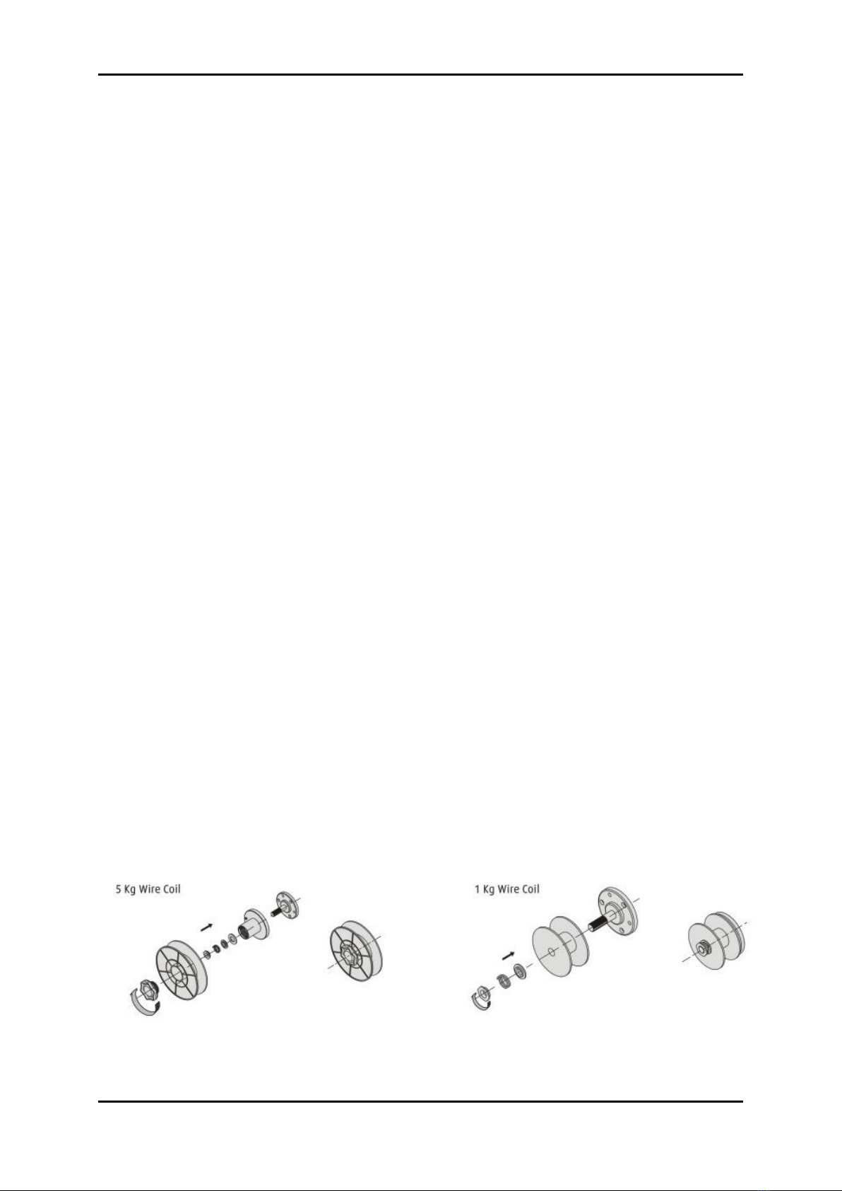
• Place the spool of welding wire spool mounting mechanism, paying attention to the direction of unwinding the
wire was in line with the direction of the entrance to the wire drive unit Lock reels from slipping by tightening
the nut on the body mounting a reel.
• End of the wire should be flat or cut off the bent section.
•In order to introduce the wire into the feeder release the pressure feed rollers.
• End of the wire inserted into the guide at the back of the tray and carry it over the driving roller introducing
nozzle of the welding gun.
•Push the wire in the groove drive roll and tighten.
•Remove the gas burner nozzles, and unscrew the contact tip.
•Switch on the device.
• Open wire welding torch so that it is simple. ATTENTION! Do not direct the tip of the welding torch in the
direction of the face or other people.
• Press welding the torch and hold until the wire for burner.
•When the end of the welding wire passes through a connector in the burner, a distance of approx. 5 cm and release the button
to establish contact tip and gas nozzle.
•Adjust the pressing force by rotation of the knob to the right - increase the biasing force to the left - decrease the pressing
force. Too little downforce, will cause slippage of the drive roller. Too high pressure causes an increase in resistance of
administration and the deformation of the wire.
Entering wire welding torch to suggest that you run closed valve on the cylinder of shielding gas. This will
reduce the unnecessary loss.
The installation of shielding gas cylinders:
• The bottle with the appropriate shielding gas, should always be protected against tipping over. If it is
possible to attach a certified welding carriage on which the MIG / MAG welding. Trolley is not a standard set
of equipment.
• Connect with semiautomatic bottle with a suitable cable.
•Unscrew the regulator valve prior to welding. After completion of welding, the cylinder valve should Unscrew the regulator valve prior to welding. After completion of welding, the cylinder valve should
always turn off.

Page 10 with 33Page 10 with 33Page 10 with 33Page 10 with 33
MANUAL - WELDER Fantasy PULSE BI-201
6. WELDING PROCESS MIG / MAG 6. WELDING PROCESS MIG / MAG
Welding gas-shielded arc (designated MIG / MAG) is one
the most widely used process for producing weldments. Abbreviation MAG (metal active gas) includes in its
description of the active shielding gases. Abbreviation MIG (Metal Inert Gas), refers to inert gas shroud.
Semi-automatic welding process involves melting the edge of the work piece and the material of the consumable
electrode arc heat glowing between the electrode in the form of a solid wire and the welded workpiece, in inert gas or
active.
Primary shielding gases for welding MIG inert gases such as argon, helium, and active gases in the MAG
CO2, H2, O2, N2 and NO, used alone or as additives in an argon or helium.
The consumable electrode is in the form of the solid wire, typically having a diameter of 0.6 to 1.2 mm, and is fed
continuously by a special supply system, a speed of 2.5 m / min and above. The welding may be water-cooled or gas
shielding. Welding is carried out mainly constant current of positive polarity as a semi-automatic welding, mechanized,
automated or robotic using specialized equipment. Glowing shield arc between the consumable electrode and the weld
material for forming the weld in a very favorable thermal and chemical conditions. Welding of this type can be used to
make high quality of the connections of all the metals which may be joined by arc welding. These include: carbon and
low-alloy steels and corrosion resistant.
MIG SINGLE PULS
Pulse MIG welding is a sophisticated form, which utilizes the best form of the transfer of the molten electrode material
on the work piece. In contrast to short-circuits, pulse welding spatter does not produce or threaten to cold "dociekiem."
In pulse welding positions are limited, as are derivatives of globular or spray forms, and their use is far more efficient.
With the cooling of the arc spray process, a pulsed MIG is able to expand the range of welding, a smaller heat input
does not cause the problem of burn-through thin materials. MIG PULSE is one of the best welding processes for a
wide range of applications and types of metal.

Page 11 with 33Page 11 with 33Page 11 with 33Page 11 with 33
MANUAL - WELDER Fantasy PULSE BI-201
DOUBLE PULSE MIG
Welding MIG / MAG double pulse obtain a high level of the appearance of the face (due to scales). In addition, the use
of an automatic wire feed affect the welding performance. MIG / MAG double pulse allows the adjustment of the
pulsation current (balance pulse) and to adjust the wire feed speed. Thanks to improve weld appearance.
During MIG / MAG welding with a double pulse, the current pulses are in two ranges. The sequencer device
automatically connects our two levels of pulses: hot and 1automatically connects our two levels of pulses: hot and 1
and cold and 2.and cold and 2.
The advantages of using MIG MAG double pulse is:
1. MIG / MAG double pulse is faster than TIG. 1. MIG / MAG double pulse is faster than TIG.
2. MIG / MAG double pulse reaches a high aesthetics TIG. 2. MIG / MAG double pulse reaches a high aesthetics TIG.
3. MIG / MAG double pulse causes less strain 3. MIG / MAG double pulse causes less strain
than TIG.

Page 12 with 33Page 12 with 33Page 12 with 33Page 12 with 33
MANUAL - WELDER Fantasy PULSE BI-201
7. OPERATION WELDER FANTASY PULSE BI-201 7. OPERATION WELDER FANTASY PULSE BI-201
AND. Control Description AND. Control Description
(Please also read the instruction film on our website and Youtube channel.)
1. LCD display 1. LCD display
2. Function key "left" during the selection of welding parameters. 2. Function key "left" during the selection of welding parameters.
3. Button to return to the previous menu. (Also hold for 5 seconds to3. Button to return to the previous menu. (Also hold for 5 seconds to
return to the factory settings (RESET)).
4. Knob of welding parameters. 4. Knob of welding parameters.
5. Authorizing the settings button and enter the next menu. 5. Authorizing the settings button and enter the next menu.
6. Function key "right" during the selection of welding parameters. 6. Function key "right" during the selection of welding parameters.

Page 13 with 33Page 13 with 33Page 13 with 33Page 13 with 33
MANUAL - WELDER Fantasy PULSE BI-201
B. LANGUAGE SELECTION B. LANGUAGE SELECTION
english
german
j.polski
j. Russian
Using the 2 or 6 select the menu language, and then confirm
selection with 5 .
The device allows you to set the following control languages: English, German, Polish and Russian.

Page 14 with 33Page 14 with 33Page 14 with 33Page 14 with 33
MANUAL - WELDER Fantasy PULSE BI-201
C. SELECTION OF WELDING METHODS C. SELECTION OF WELDING METHODS
Using the 2 or 6 select the desired method of welding, and then
confirm by pressing 5
AUTO mode - setting synergistic. The user selects the basic welding parameters such as type of material, the plate AUTO mode - setting synergistic. The user selects the basic welding parameters such as type of material, the plate
thickness, the diameter of the welding wire. Other parameters of the device selects automatically uploaded using the
base program.
MIG mode - welding of individual students using the user's settings. The system prompts the selection of key welding MIG mode - welding of individual students using the user's settings. The system prompts the selection of key welding
parameters indicating the adjustment of the plate thickness. This information suggests the user to correct settings
made.
Lift TIG mode ( arc ignition by friction) - welding the tungsten electrode in inert gas. In order to perform welding by this Lift TIG mode ( arc ignition by friction) - welding the tungsten electrode in inert gas. In order to perform welding by this
method it is necessary to retrofit device TIG adjustable shielding gas in the handle as in the following image. This method it is necessary to retrofit device TIG adjustable shielding gas in the handle as in the following image. This
handle is not a standard set of equipment.
MMA mode - welding coated electrode. User-adjustable welding current can also set the ARC-FORCE, HOT START MMA mode - welding coated electrode. User-adjustable welding current can also set the ARC-FORCE, HOT START
and enable or disable the protective system VRD.
ARC FORCE - stabilizes the arc regardless of variations in its length, reduces the amount of spatter.
HOT START - start function for easy welding. Upon ignition of the arc is temporarily increased welding
current in order to heat the material and the contact point electrode and the proper formation of welds and
weld face at the initial stage of welding.
VRD - the device has a system VRD (Voltage Reduction Device) which mode MMA Rutile and basic
electrodes lowers the load voltage, which greatly enhances user safety. In special cases, the use of
electrodes with high current arc ignition problems can occur at his initiation.

Page 15 with 33Page 15 with 33Page 15 with 33Page 15 with 33
MANUAL - WELDER Fantasy PULSE BI-201
D. AUTO Mode (MIG / MAG) D. AUTO Mode (MIG / MAG)
In the AUTO mode, a user makes a selection of only the basic welding parameters such as type of material,
the plate thickness, the diameter of the welding wire (available 0.8 mm, 1.0 mm and 1.2 mm). Other parameters of the
device selects automatically uploaded using the base program. AUTO mode only allows continuous welding device selects automatically uploaded using the base program. AUTO mode only allows continuous welding
current
-there is no possibility of adjusting the settings mode and dual PULS PULS.
There is a possibility of manual adjustments to the synergistic.
ATTENTION: If you change the type of material and its thickness, the system returns with the other parameters to the ATTENTION: If you change the type of material and its thickness, the system returns with the other parameters to the
factory defaults.
Step 1 Choose material
The user selects the welding material (wire and
welding) from the list of alloys available in the
program.
Step 2 Select the thickness of the welded material
The user selects thickness of the welded material. The
device on the ground automatically adjusts the welding
current, arc voltage and welding speed of the feeder.
0.8mm wire
Step 3 Select the diameter of welding wire
The user selects the diameter of welding wire, which it
plans to use.
ATTENTION!
The device automatically increases or reduces its
maximum power depending on the diameter of the wire.

Page 16 with 33Page 16 with 33Page 16 with 33Page 16 with 33
MANUAL - WELDER Fantasy PULSE BI-201
1.0mm wire
Step 3 Select the diameter of welding wire
The user selects the diameter of welding wire, which it
plans to use.
ATTENTION!
Device automatically decreases
or increase its maximum power depending on the
diameter of the wire.
1.2mm wire
Step 3 Select the diameter of welding wire
The user selects the diameter of welding wire, which it
plans to use.
ATTENTION!
Device automatically decreases
or increase its maximum power depending on the
diameter of the wire.
According to the adopted values of the welding parameters in software user-selected diameter of the welding wire has
a direct impact on the current and welding voltage and wire feed speed. For example, the choice of wire with a
diameter of 0.8 mm will automatically limit the maximum welding current for example. 140A, the selection of wire
1,0mm allow welding current of 200A. These activities aim to optimize the welding process and avoid the problems
associated with too fast of burning wire just behind the tip in the current situation where there is no further possibility of
increasing the speed of the feeder.
Inability to set the maximum welding current is not a software error and results from selected diameter
welding wire.

Page 17 with 33Page 17 with 33Page 17 with 33Page 17 with 33
MANUAL - WELDER Fantasy PULSE BI-201
E. BASIC SETTINGS MIG / MAG E. BASIC SETTINGS MIG / MAG
In MIG mode you yourself shall subsequently setting all welding parameters. The system prompts the In MIG mode you yourself shall subsequently setting all welding parameters. The system prompts the
selection of the optimum welding parameters indicating the adjustment of the plate thickness of the material (see table
- set the wire feed speed). This information suggests the user to correct settings made. Depending on the style of
welding (forced position, welding current rapidly with a higher intensity of slower or lower current density), the settings
may require slight adjustment by the user.
Plowing mode button on the torch 2-stroke
and 4-stroke.
Selection of welding current:
-constant (no pulse)
-a single pulse (see MIG / MAG welding with
pulsing)
-double pulse (see MIG / MAG double pulse)
The choice of the diameter of welding wire

Page 18 with 33Page 18 with 33Page 18 with 33Page 18 with 33
MANUAL - WELDER Fantasy PULSE BI-201
The choice of base material (and welding wire) from the
list of alloys available in the program.
Setting the wire feed speed.
ATTENTION!
In the red marked with "x" indicated automatically
estimated plate thickness with a view to selecting the
optimal parameters of welding.
voltage regulation bow welding.
Increasing or decreasing this value to lengthen or
shorten the arc length spawaniczego.
Adjusting the inductance.
Appropriately selected inductance welding helps to
reduce the amount of spatter. Is
she depending on the wire diameter
welding, shielding gas, current and welding position.
Reducing the inductance makes the arc becomes more
stable and
concentrated and increase
contributes to the formation of a more liquid
lakes and decrease amounts
spatter. Correctly characterized by
stable arc, steady
moving the droplet liquid metal,
maintaining constant the size of the weld pool
and characteristic
repetitive sound without splashes and explosions.

Page 19 with 33Page 19 with 33Page 19 with 33Page 19 with 33
MANUAL - WELDER Fantasy PULSE BI-201
F. MIG / MAG Pulse F. MIG / MAG Pulse
In order to start welding mode MIG / MAG PULSE be pre-made settings as in the previous chapter. Additional
welding parameters in pulsed mode welding shown in the following tables:
Selecting the welding current 2 - single pulse of the pulsed Selecting the welding current 2 - single pulse of the pulsed Selecting the welding current 2 - single pulse of the pulsed Selecting the welding current 2 - single pulse of the pulsed
current function, is used mainly in welding of thin
elements, metals having a low melting point, eg. lead,
and in welding forced positions. Other advantages of
pulsed welding is less heat-affected zone, the greater the
stability of the welding arc and the greater the depth of
penetration and improving the appearance of the weld
face.
Adjusting the frequency of the pulse. Changing this
parameter results in lengthening or shortening the arc.
ATTENTION!
Frequency pulse selected is
automatically on the basis of other welding parameters,
there is no need for manual correction dokonowyania
her.
Setting cycle pulse. Control
this parameter causes
increasing or decreasing the amount of spatter during
welding.
ATTENTION!
Value cycle pulse selected is
automatically on the basis of other welding parameters,
there is no need for manual correction dokonowyania
her.

Page 20 with 33Page 20 with 33Page 20 with 33Page 20 with 33
MANUAL - WELDER Fantasy PULSE BI-201
G. MIG / MAG WITH DOUBLE PULSE G. MIG / MAG WITH DOUBLE PULSE
In order to start welding mode MIG / MAG PULSE be double pre-made settings as in Chapter
BASIC SETTINGS
In order to start welding mode MIG / MAG PULSE be double pre-made settings as in Chapter
BASIC SETTINGS
MIG / MAG welding.
Additional welding parameters in the welding mode, double-pulse current shown in the following
MIG / MAG welding.
Additional welding parameters in the welding mode, double-pulse current shown in the following
tables:
Selecting the welding current 3 - double pulse Selecting the welding current 3 - double pulse Selecting the welding current 3 - double pulse Selecting the welding current 3 - double pulse
Setting the maximum speed wire feeder.
ATTENTION!
When adjusting this parameter should pay particular
attention to the box marked red
trademarks "X" pointing
suggested the plate thickness.
Setting the frequency of the double pulse. In order to
achieve optimum welding parameters is suggested to set
the range of 1 to 2 Hz.
Setting the cycle of the double pulse. In order to achieve
optimum welding parameters is suggested that the setting in
the range of from 30 to 40%.
Table of contents
Other FACHOWIEC Welding System manuals