fadini Jubi 433 User manual

GB
®
the gate opener
ENCODING INSTRUCTIONS
RADIO TRANSM ITTER JUBI• 433

2
RADIO RECEIVER EXTERNAL TYPE. ENCODING INSTRUCTIONS AND WORKING PRINCIPLE
LED
2nd PUSH
BUTTON
TRANSM ITTER
JUBI-SM ALL•433
2 CHANNELS
TRANSM ITTER
JUBI•433
4 CHANNELS
LED
ANY BUTTON IN THE TRANSM ITTER CAN BE PRESSED TO OPERTE ANY REQUIRED CHANNEL, PROVIDED THAT THE “ STRIP” IS INSERTED IN THE PROPER “ PIN” CONNECTORS
THAT CORRESPOND TO THE DESIRED CHANNEL. ENCODE THE UNIT AS DESCRIBED.
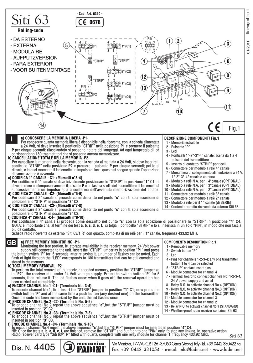
The instructions that follow explain how to set a personalized code (ie. user’s code) with any one receiver. First supply 24 Volt a.c. pow er to terminals 1 (–) and 2 (+) in the
receiver terminal board - then insert the “ STRIP” as in position “ C1” . This activates the relay “ 1R” that corresponds to terminals 3 and 4 (CHANNEL No. 1). The next step is
to press simultaneously the switch button “ P” on the receiver PC board and the switch button “ T” (any desired one) on the transmitter for about five seconds. Once the code
has been memorized by the unit, the “ LED” on the receiver PC board switches on. Release the transmitter button and the receiver switch button; remove the “ STRIP” jumper
and insert it on to a “ PIN” connector on standby. Now the radio remote control set has been encoded with a personalized, secret code and is ready to w ork. Repeat the above
sequence for channels 2-3-4. Insert the “ STRIP” jumper in the correct position as required, as follows:
Position “ C2“ . It corresponds to relay No. 2(2R) - Channel No. 2. - Terminals 5-6
Position “ C3“ . It corresponds to relay No. 3(3R) - Channel No. 3. - Terminals 7-8
Position “ C4“ . It corresponds to relay No. 4(4R) - Channel No. 4. - Terminals 9-10
SHOULD THE POWER SUPPLY FAIL OR THE 24 V a.c. - 12 Vd.c. BE DISCONNECTED FROM THE RECEIVER, THE USER’S CODE IS RETAINED IN THE REM OVABLE M EM ORY THAT
CAN BE FITTED ON TO ANOTHER CARD.
Drw g. No. 3706
RECEIVER FOR EXTERNAL APPLICATION
AERIAL
REM OVABLE
M EM ORY
CHANNEL 1
SWITCH BUTTON “ P“
“ STRIP“
JUM PER
24 V a.c.
POWER SUPPLY
PIN
CHANNEL 4
CHANNEL 3
CHANNEL 2
–
1st PUSH
BUTTON

TECHNICAL SPECIFICATIONS. RADIO RECEIVER EXTERNAL TYPE AND TRANSM ITTER
3
Made in Italy
Jubi 4 3 3
0678
433,92 MHz “Rolling-Code”
Drw g. No. 3707
TRANSM ITTER
Jubi•433 - 4 CHANNELS
84x43x17 mm
SHOULD THE POWER SUPPLY FAIL OR THE 24 V a.c. - 12 Vd.c. BE DISCONNECTED FROM THE RECEIVER, THE USER’S CODE IS RETAINED IN THE REM OVABLE M EM ORY THAT
CAN BE FITTED ON TO ANOTHER CARD.
RADIO RECEIVER TECHNICAL SPECIFICATIONS
Working frequenc y.............................................................................................................433.92 M Hz
Sensitivity (to operating pulse)..................................................................................................> 1 uV
Distance range ....................................................................................................................100 meters
Power supply w ith alternated current...................................................................24 Vac (+/–10%)
Power supply w ith direct current .....................................................................12 Vdc (+ 20% –5%)
Working absorption...........................................................................25 mA (1st energized channel)
Standby absorption .....................................................................................................................10 mA
Decrypt ......................................................................................................................................DIGITAL
No. of channels .....................................................................................................................................4
Changeover contact relay.................................N.O. (Channel 1) - N.O. or N.C. (Channels 2-3-4)
Relay rating ...................................................................................................................0,5 A –125 Vac
Excitation time ...........................................................................................200 ms (1 complete code)
Dropout time.........................................................................................300 ms (from last valid code)
Working temperature....................................................................................................–10°C + 55°C
* Channel 1 module is factory fitted. Fit the other relay modules into the respective connectors for
the remaining channels.
RADIO RECEIVER FOR EXTERNAL APPLICATION
TRANSM ITTER TECHNICAL SPECIFICATIONS
Working frequenc y.............................................................................................................433.92 M Hz
Carrier frequency tolerance ...............................................................................................+/–75 KHz
Radiated pow er .........................................................................................................................100 uW
Band width ................................................................................................................................>25 KHz
Apparent pow er of the harmonic products.......................................................<–54 dBm (<4 uW)
Supply voltage ..........................................................................................12 Vdc -23 A (+20% –50%)
M ean absorption .........................................................................................................................14 mA
Working temperature.......................................................................................................–40°C +85°C
No. of channels .....................................................................................................................................4
Distance range ....................................................................................................................120 meters
Code type...........................................................................DIGITAL (264 encrypted) “Rolling-Code“
•A radio signal is activated by pressing a button in the transmitter and stays on as long as
the button is kept dow n. A red led sw itches on to confirm the signal.
•An electric contact is closed instantaneously on releasing the button and the unit becomes
operating.
•Replace the 12V battery should the led flash on/off on pressing the button.
•To achieve best performance of the aerial, make sure that the core and the braided wire
of the coaxial cable are connected to their respective terminals as indicated.
•Keep the transmitter away from heat sources and handle it w ith care.
•Dispose properly of run dow n batteries.
PIN COM BINATIONS
FREE M EM ORY
Relay 1
Relay 2
Relay 3
Relay 4
RADIO RECEIVER
FOR EXTERNAL
APPLICATION
60x52x1,6 mm AERIAL
REM OVABLE
M EM ORY
CHANNEL 1
SWITCH BUTTON “P“
“STRIP“
JUM PER
24 V a.c.
POWER SUPPLY
PIN
CHANNEL 4
CHANNEL 3
CHANNEL 2
TOTA L M EM ORY REM OVAL

4
SELF-LEARNING PLUG-IN CARD. ENCODING INSTRUCTIONS AND WORKING PRINCIPLE
PLUG-IN RADIO RECEIVER CARD
PLUG-IN
CONNECTOR
PIN
ELECTRONIC
CONTROL PANEL
TYPE ELPRO
POWER SUPPLY 230 V
LED
LED
ANY BUTTON IN THE TRANSM ITTER CAN BE SELECTED TO OPERATE ANY REQUIRED CHANNEL. INSERT THE
JUM PER IN THE DESIRED POSITION. ENCODE THE UNIT AS DESCRIBED.
How to set a personalized code (ie. user’s code) with a plug-in type receiver card. First supply it w ith power by
plugging it into an operating control box. Then insert the “STRIP”jumper as in position “C1”. This activates the relay
“1R”that is directly connected to the respective circuit in the control panel. The next step is to press simultaneously
the switch button “P”on the receiver card and a push button (any desired one) on the transmitter for about five
seconds. Once the code has been memorized by the unit, the led on the receiver card switches on. Release the
transmitter button and receiver switch button; remove the “STRIP”jumper and insert it on to one “PIN”only. Now
the radio remote control set has been encoded with a personalized secret code and is ready to work. Repeat the
above sequence to encode channel No. 2, which provides an extra output for user’s personal applications, but the
jumper must be inserted in position “C2”to activate the second relay “2R”through another transmitter button. The
connection to output for channel 2 can either be normally open or closed (N.O. - N.C.) to meet all possible applications.
SHOULD THE POWER SUPPLY FAIL OR THE 24 V a.c. - 12 Vd.c. BE DISCONNECTED FROM THE RECEIVER, THE USER’S CODE IS RETAINED IN THE REM OVABLE M EM ORY THAT
CAN BE FITTED ON TO ANOTHER CARD.
Drw g. No. 3751
~24 V
–+
REM OVABLE
M EM ORY
CHANNEL 1
SWITCH BUTTON “P“
“STRIP“
JUM PER
2nd PUSH
BUTTON
TRANSM ITTER
JUBI-SM ALL•433
2 CHANNELS
TRANSM ITTER
JUBI•433
4 CHANNELS
1st PUSH
BUTTON

TECHNICAL SPECIFICATIONS. PLUG-IN RADIO RECEIVER AND TRANSM ITTER
5
Made in Italy
0678
433,92 MHz “Rolling-Code”
Jubi 433
Small
Drw g. No. 3702
SWITCH BUTTON “P““STRIP“
JUM PER
PLUG-IN CONNECTOR
PIN
TRANSM ITTER Jubi-Small• 433, 2 CHANNELS, 40x48x14 mm
REM OVABLE
M EM ORY
PLUG-IN RADIO RECEIVER 56x43x1,6 mm
Relay 2
Relay 1
P2
P1
(C2)
(C1)
SHOULD THE POWER SUPPLY FAIL OR THE 24 V a.c. - 12 Vd.c. BE DISCONNECTED FROM THE RECEIVER, THE USER’S CODE IS RETAINED IN THE REM OVABLE M EM ORY THAT
CAN BE FITTED ON TO ANOTHER CARD.
PLUG-IN RADIO RECEIVER TECHNICAL SPECIFICATIONS
Working frequenc y.............................................................................................................433.92 M Hz
Sensitivity (to operating pulse)..................................................................................................> 1 uV
Distance range ....................................................................................................................100 meters
Power supply w ith alternated current...................................................................24 Vac (+/–10%)
Power supply w ith direct current .....................................................................12 Vdc (+ 20% –5%)
Working absorption...........................................................................25 mA (1st energized channel)
Standby absorption .....................................................................................................................10 mA
Decrypt ......................................................................................................................................DIGITAL
No. of channels .....................................................................................................................................2
Changeover contact relay..........................................N.O. (Channel 1) - N.O. or N.C. (Channel 2)
Relay rating ...................................................................................................................0.5 A –125 Vac
Excitation time ...........................................................................................200 ms (1 complete code)
Dropout time.........................................................................................300 ms (from last valid code)
Working temperature....................................................................................................–10°C + 55°C
TRANSM ITTER TECHNICAL SPECIFICATIONS
Working frequenc y.............................................................................................................433.92 M Hz
Carrier frequency tolerance ...............................................................................................+/–75 KHz
Radiated pow er .........................................................................................................................100 uW
Band width ................................................................................................................................>25 KHz
Apparent pow er of the harmonic products.......................................................<–54 dBm (<4 uW)
Supply voltage ..........................................................................................12 Vdc -23 A (+20% –50%)
M ean absorption .........................................................................................................................12 mA
Working temperature.......................................................................................................–40°C +85°C
No. of channels .....................................................................................................................................2
Distance range ....................................................................................................................120 meters
Code type...........................................................................DIGITAL (264 encrypted) “Rolling-Code“
•A radio signal is activated by pressing a button in the transmitter and stays on as long as
the button is kept dow n. A red led sw itches on to confirm the signal.
•An electric contact is closed instantaneously on releasing the button and the unit becomes
operating.
•Replace the 12V battery should the led flash on/off on pressing the button.
•To achieve best performance of the aerial, make sure that the core and the braided wire
of the coaxial cable are connected to their respective terminals as indicated.
•Keep the transmitter away from heat sources and handle it w ith care.
•Dispose properly of run dow n batteries.
PIN COM BINATIONS
FREE M EM ORY
TOTA L M EM ORY REM OVAL

6
TO STORE OTHER TRANSM ITTER CODES INTO THE SAM E RECEIVER M EM ORY
PREVIOUSLY ENCODED
TRANSM ITTER
RECEIVER
ALREADY
CONNECTED
1st CHANNEL (No. 3-4)
POWER SUPPLY
~24 VOLT a.c.
(No. 1-2)
AERIAL
BLANK
TRANSM ITTER
HOW TO DUPLICATEORENCODE NEW TRANSM ITTERS, W HICH ARETO OPERATE
THE SAM E RECEIVER. IT IS REQUIRED TO PERFORM TW O OPERATIONS IN A
SEQUENCE, AND A PREVIOUSLY ENCODED TRANSM ITTER M UST BE AVAILABLE.
ENCODING OPERATIONS ARE TO BE PERFORM ED AT A RECOM M ENDED
DISTANCE, ie. 10 TO 20 M ETRES FROM THE OPERATIVE RECEIVER AND ARIAL.
1
st
OPERATION
A new transmitter “A”(blank, ie. not previously encoded) is available. Press
any two buttons simultaneously for 10 seconds. Release the buttons and carry
on the 2nd operation within 15 seconds.
2
nd
OPERATION
Transmitter “B”(previously encoded) is available; Press two buttons
(corresponding to those in transmitter “ A” ) simultaneously for 10 seconds.
Once the buttons are released, the receiver can read the code from the new
transmitter w hen this is used.
THE ABOVE SEQUENCE OF OPERATIONS IS TO BE REPEATED W ITH EACH NEW
TRANSM ITTER THAT IS REQUIRED TO BE USED ALONG WITH THE EXISTING
ONES.
WHEN TWO BUTTONS ARE PRESSED SIM ULTANEOUSLY NO RELAY IS
ACTIVATED.
AB
A B
–+

HOW TO ERASE A TRANSM ITTER CODE FROM A RECEIVER
7
1st Sequence TWO buttons
2nd Sequence ONE button
3rd Sequence TW O buttons
4th Sequence ONE button
5th SequenceTWO buttons
10 sec. TIM E
STAND ALONE RADIO RECEIVER CARD PLUG-IN RADIO RECEIVER CARD
THIS EXPLAINS HOW TO ERASE A TRANSM ITTER CODE FROM A RECEIVER.
ALTERNATING OPERATIONS ARE TO BE PERFORM ED IN A SEQUENCE WITH THE
SAM E TRANSM ITTER. RECOM M ENDED DISTANCE FROM THE OPERATIVE RECEIVER
AND AERIAL IS 10 TO 20 M ETRES.
Operative sequence
Insert the jumper “STRIP”as in position “P1”(if not already pre-set)
1st Operation. Press two buttons on the transmitter simultaneously. Release the
buttons. Proceed to the 2nd operation.
2nd Operation. Press one button only (as in the picture), then release it and proceed
to the 3rd operation, ie. press again the tw o buttons simultaneously. In other words
you repeat the first two operations alternately 5 times in total, as in the picture. The
limit time between one operation and the other is 10 seconds.
SHOULD IT BE REQUIRED TO ERASE SEVERAL TRANSM ITTER CODES, THE ABOVE
SEQUENCE M UST BE PERFORM ED INDIVIDUALLY FOR EACH TRANSM ITTER.
SHOULD YOU FAIL TO COUNT THE OPERATIONS IN THE CORRECT SEQUENCE OR PRESS THE WRONG BUTTONS, YOU HAVE TO START FROM THE BEGINNING. WAIT ONE
M INUTE BEFORE REPEATING THE SEQUENCE. M AKE SURE THAT THE RECEIVER HAS VOLTAGE.
TRANSM ITTER Jubi•433,
4 CHANNELS
TRANSM ITTER Jubi-Small•433,
2 CHANNELS
“STRIP“
JUM PER
AERIAL
CHANNEL 1
24 V a.c.
POWER SUPPLY
CHANNEL 4
CHANNEL 3
CHANNEL 2
“STRIP“
JUM PER

8
FREE M EM ORY M ONITORING P1 Jubi• 433 – “ROLLING-CODE“
RADIO RECEIVER Jubi•433 EXTERNAL USE - 4 CHANNELS
STABILIZED RESONATOR, 433.92 M Hz, SELF LEARNING, “ROLLING-CODE“
RADIO RECEIVER Jubi•433 PLUG-IN TYPE - 2 CHANNELS
STABILIZED RESONATOR, 433.92 M Hz, SELF LEARNING, “ROLLING-CODE“
M onitoring the free portion, ie. storage availability in the receiver memory. 24 Volt power supply still connected to the unit. Insert the “STRIP”jumper as in position “P1”(PIN)
and press the button switch “P”for 5 seconds: after releasing it, a number of flashes can be noted. Each flash of light through the “LED”corresponds to 25 transmitters that
can be still encoded and stored in the memory. - Example: 7 flashes of light can be counted. It means: 25 still available codes times 7, ie. the No. of the flashes is equal to
175, ie. the number of transmitters that can still be encoded and stored. Once the test is finished, remove the “STRIP”and put it on to one pin only to stop any linking, ie.
operative action.
FOR ENCODING AND STORING OPERATIONS WITH OTHER TRASM ITTERS FOLLOW THE INSTRUCTIONS ON DRAW. 3706 - 3751.
“STRIP“
CODIER-
BRÜCKE
PLUG-IN
CONNECTOR
PIN
– +
433,92 MHz RESONATOR STABILISIERT “Rolling-Code”
Jubi 433
AERIAL
REM OVABLE
M EM ORY
CHANNEL 1
SWITCH
BUTTON “P“
“STRIP“
JUM PER
24 V a.c.
POWER SUPPLY
PIN
CHANNEL 4
CHANNEL 3
CHANNEL 2
SWITCH
BUTTON “P““STRIP“
JUM PER
REM OVABLE
M EM ORY

TOTAL M EM ORY REM OVAL P2 Jubi• 433 – “ROLLING-CODE“
9
RADIO RECEIVER Jubi•433 EXTERNAL USE - 4 CHANNELS
STABILIZED RESONATOR, 433.92 M Hz, SELF LEARNING, “ROLLING-CODE“
RADIO RECEIVER Jubi•433 PLUG-IN TYPE - 2 CHANNELS
STABILIZED RESONATOR, 433.92 M Hz, SELF LEARNING, “ROLLING-CODE“
To perform the total removal of the receiver encoded memory, position the “STRIP”as in “P2”, the receiver still under 24 V a.c. - 12 Vd.c. voltage supply. Press the switch
button “P” for 5 seconds, then release it. The led flashes once to confirm that the removal operation has been carried out completely. Remove the “STRIP”and position it on
to one “PIN”only to prevent any operative action.
TO ENCODE NEW AND EXISTING TRANSM ITTERS AND STORE THEIR CODES ANEW IN THE RECEIVER MEMORY KEEP TO THE INSTRUCTIONS ON DRAW. 3706 - 3751.
“STRIP“
CODIER-
BRÜCKE
PIN
– +
433,92 MHz RESONATOR STABILISIERT “Rolling-Code”
Jubi 433
AERIAL
REM OVABLE
M EM ORY
CHANNEL 1
SWITCH
BUTTON “P“
“STRIP“
JUM PER
24 V a.c.
POWER SUPPLY
PIN
CHANNEL 4
CHANNEL 3
CHANNEL 2
PLUG-IN
CONNECTOR
SWITCH
BUTTON “P““STRIP“
JUM PER
REM OVABLE
M EM ORY

10
Jubi•433 - 4 CHANNELS
COLOUR
: M ETAL BLACK
NIGHT BLUE BUTTONS
M ATERIAL ABS = B70 SINKRAL
ROUND LENS
TRANSM ITTER COVER
FOUR BUTTON ARRAY
TRANSM ITTER ELECTRONIC CARD
TRANSM ITTER CASING
12 Vd.c. –23 A (+ 20% –50%) BATTERY
BATTERY BRACKET
FIXING SCREW
Jubi-Small•433 - 2 CHANNELS
COLOUR
: NIGHT BLUE
LILY-SHAPED TRANSPARENT LENS
TRANSM ITTER COVER
TRANSM ITTER CASING
TRANSM ITTER ELECTRONIC CARD
BATTERY BRACKET
12 Vd.c. –23 A (+ 20% –50%) BATTERY
FIXING SCREW

11
OVERALL DIM ENSIONS
Made in Italy
Jubi 433
0678
433,92 MHz “Rolling-Code”
PLUG-IN CARD TYPE
Jubi•433 - 2 CHANNELS
4 CHANNELS
RADIO RECEIVER EXTERNAL TYPE
Jubi•433 - 4 CHANNELS
73
91
27
68
210
Made in Italy
0678
433,92 MHz “Rolling-Code”
Jubi 433
Small
2 CHANNELS
76
84
17
43
48
40
14
8
56
43

AUTOM ATIC GATE M AN UFACTURERS
®
s.n.c.
Via M antova, 177/A - 37053 Cerea (Verona) Italy - Tel. 0442 330422 r.a. - Fax 0442 331054 - e-mail: info@fadini.net - w w w.fadini.net
M ade in Italy
®
10-2003 Lineagrafica
Other manuals for Jubi 433
1
Table of contents
Other fadini Transmitter manuals
Popular Transmitter manuals by other brands

RKI Instruments
RKI Instruments 65-2646XLS-SW Operator's manual

Czerf
Czerf CZH-7C quick start guide

Keysight Technologies
Keysight Technologies E6960A 1000Base-T1 User Guide and Method of Implementation

BKM
BKM FTC1 user manual

Pixsys
Pixsys DST100 user manual

AVK
AVK 3001/003 Installation, operation and maintenance manual