fadini Siti 63 User manual

®
GB
I

®
NL
F
D
E

a) CONOSCERE LA MEMORIA LIBERA -P1-
Per conoscere quanta memoria libera è disponibile nella ricevente, con la scheda
alimentata a 24 Volt, si deve inserire il ponticello “STRIP” nella posizione “P1” e
premere il pulsante “P” per cinque secondi: rilasciandolo si possono notare dei lampeggi.
Ad ogni lampeggio di led corrispondono 180 trasmettitori che si possono ancora
memorizzare.
b) CANCELLAZIONE TOTALE DELLA MEMORIA -P2-
Per cancellare la memoria nella ricevente, con la scheda alimentata a 24 Volt, si deve
inserire il ponticello “STRIP” nella posizione “P2” e premere il pulsante “P” per cinque
secondi; poi lo si rilascia, e in quel momento il led emette un impulso di luce: questo si
spegne quando l’operazione di cancellazione è avvenuta.
c) CODIFICA 1°CANALE -C1- (Connettore innesto)
Per codificare il 1°canale si deve inizialmente posizionare lo “STRIP” in posizione “1” C1;
si deve premere contemporaneamente il pulsante “P” e poi un tasto a scelta del
trasmettitore. Il led emetterà successivamente un impulso spia a conferma dell’avvenuta
memorizzazione del codice.
d) CODIFICA 2°CANALE -C2- (Morsetti n°3-4-5)
Per codificare il 2°canale si procede come descritto nel punto “c” con la sola eccezione di posizionare lo “STRIP” in posizione “2” C2.
NOTA: è importante che, al termine dei test a, b, c, d, si tolga il ponticello “STRIP” e lo si inserisca in un solo “PIN”, in modo che non faccia
più da contatto. Scheda ad innesto radio ricevente “Siti 63/2 R” con quarzo, completa di due moduli relè per il 1°e 2°canale, frequenza
433.92 MHz.
a) FREE MEMORY MONITORING -P1-
Monitoring the free portion, ie. storage availability in the receiver memory. 24 Volt
power supply still connected to the unit. Insert the “STRIP” jumper as in position “P1”
and press the button switch “P” for 5 seconds: after releasing it, a number of flashes can
be noted. Each flash of light through the “LED” corresponds to 180 transmitters that can
be still encoded and stored in the memory.
b) TOTAL MEMORY REMOVAL -P2-
To perform the total removal of the receiver encoded memory, position the “STRIP”
jumper as in “P2”, the receiver still under 24 Volt voltage supply. Press the switch button
“P” for 5 seconds, then release it. The led flashes once; when it goes off, the removal
operation has been carried out completely.
c) ENCODE CHANNEL No.1 -C1- (Plug-on connector)
To encode channel No.1, first insert the “STRIP” jumper in position “1” C1; now press the
switch button “P” and at the same time a push button (any desired one) on the
transmitter. Once the code has been memorized by the unit, the led flashes once.
d) ENCODE CHANNEL No.2 -C2- (Terminals 3-4-5)
To encode channel No.2 repeat the above sequence “c”,but the “STRIP” jumper must be inserted in position “2” C2.
NB: Once the tests a, b, c, d, are finished, remove the “STRIP” and put it on to one “PIN” only, to stop any linking, ie. operative action.
Plug-in radio receiver card type “Siti 63/2 R” fitted with quartz, complete with two relay modules for channels 1 and 2, frequency
433.92MHz.
Dis. N. 4406 ®
GB
Fig.1
DESCRIZIONE COMPONENTI Fig.1
1 - Memoria estraibile
2 - Pulsante “P”
3 - Inserto di contatto “STRIP” ponticelli
4 - Ponticelli 1°-2°canale: scelta da 1 a 4
pulsanti del trasmettitore
5 - Led
6 - Relé per attivare il 2°canale
7 - Morsettiera di collegamento 2°canale
contatto N.C.-N.A. e antenna (morsetti 1-2)
8 - Connettore ad innesto femmina 1°canale e
alimentazione a 24 V
9 - Relé per attivare il 1°canale
10 - Programmatore elettronico serie Elpro
11 - Connettore ad innesto maschio
I
- DA INNESTO
- PLUG-IN
- ENFICHABLE
- EINSTECKVERSION
- ENCHUFABLE
- MET KOPPELING
COMPONENTS DESCRIPTION Pic.1
1 - Removable memory
2 - Switch button “P”
3 - “STRIP” contact insert pins
4 - Pins for channels 1-2: any one transmitter
button 1 to 4 can be selected
5 - Led
6 - Relay to activate channel No.2
7 - Terminal to connect N.O. n N.C. channel
No.2 and aerial (Terminals 1-2)
8 - Female plug-on connector channel 1 and 24 V
power supply
9 - Relay to activate channel No.1
10 - Electronic programmer Elpro series
11 - Male plug-on connector
Rolling-code
- Cod. Art. 6311 -
0678
10
11
ANTENNA
1
2
3
4
5
1°R
2°R
Siti
Siti 63
Siti 63
12
4
5
6
3
PIN
NA
NC
(C1)
1°
1°R
2°R
1
2
3
4
5
+
–
“STRIP”
1
1
2C2 P2
C1 P1
1
2
P1
“STRIP”
1
2
P2
“STRIP”
Siti
(C2)
2°
2
“STRIP”
Via Mantova, 177/A - 37053 Cerea (Verona) Italy -
Tel. +39 0442 330422 r.a.
02-2009
78
9

a) PRÜFEN WIEVIEL PLATZ IM SPEICHER FREI IST -P1-
Um zu erfahren wieviel Platz in dem Speicher des Empfängers noch vorhanden ist, muss man bei mit 24
Volt gespeistem Modul die “STRIP” Codierbrücke in die Position “P1” einfügen und die Taste “P” 5 Sekunden
lang drücken: lässt man die Taste los, so kann man ein Blinken erkennen. Jedem Blinken des LEDs entsprechen
180 Handsender, die noch gespeichert werden können.
b) KOMPLETTES LÖSCHEN DES SPEICHERS -P2-
Um den gesamten codierten Speicher auf dem Funkempfänger zu löschen, den “STRIP” Codierbrücke in Position
“P2” stecken, wobei die Platine immer mit 24 Volt versorgt wird. Die Taste “P” muss 5 Sekunden lang gedrückt
werden, danach lässt man sie los, in diesem Moment sendet das LED einen Lichtimpuls, wenn der ausgeht, d.h.
dass der Löschvorgang erfolgt ist.
c) EINGABE 1. KANAL -C1- (Einsteckverbinder)
Um den 1. Kanal zu codieren, die “STRIP” Brücke in die Position “1” C1 stecken, danach die Taste “P” und
dann eine Taste des Handsenders (nach Wahl) gleichzeitig drücken. Dadurch wird die LED Signalleuchte aufleuchten,
wodurch uns die erfolgte Einspeicherung des Codes bestätigt wird.
d) EINGABE 2. KANAL -C2- (Klemmen 3-4-5)
Um dem 2. Kanal zu kodieren, wie oben Position “c” beschrieben vorgehen, die einzige Unterschied ist, dass
die “STRIP” Brücke in die Position “2” C2 gesteckt wird.
NB: Nachdem man die Test a,b,c,d, durchgeführt hat, die “STRIP” Codierbrücke entfernen und sie in einen einzigen “PIN” stecken, damit er keinen Kontakt mehr macht.
Einsteck-Empfänger “Siti 63/2 R” mit Quarz komplett mit zwei Relaismodulen für den 1. und 2. Kanal, Frequenz 433.92 MHz.
a) CONNAITRE LA MEMOIRE LIBRE -P1-
Pour connaître combien de mémoire libre il y a dans le récepteur radio, avec la carte alimenté à 24 Volt, on doit
introduire le pontage “STRIP” dans la position “P1” et appuyer la touche “P” pour 5 secondes: ensuite on peut
noter des clignotements. Chaque clignotement de led correspond à 180 émetteurs qu’on peut encore mémoriser.
b) EFFACER TOTALEMENT LA MEMOIRE -P2-
Pour effacer totalement la mémoire d’un récepteur, et donc tous les émetteurs enregistrés, il faut que la carte
soit alimentée en 24 Volts. Vous devez ensuite insérer le pontage “STRIP” sur la position “P2” et actionner le
poussoir “P” durant 5 secondes, puis le relâcher. Un moment après, la led de signalisation émettra une impulsion
lumineuse qui s’éteindra quand l’opération d’effacement est terminée.
c) MEMORISATION 1er CANAL -C1- (Connecteur enfichable)
Pour rentrer le 1er canal, il faut d’abord mettre le pontage “STRIP” sur la position “1” C1; appuyer au même
moment sur le poussoir “P” du récepteur et puis sur une touche de l’émetteur. Lorsque le code est enregistré le
voyant “LED” s’allume pour confirmer la prise en compte du code.
d) MEMORISATION 2ème CANAL -C2- (Bornes 3-4-5)
Pour rentrer le 2ème canal procéder de la même façon que ci-dessus en mettant le pontage “STRIP” sur la position “2”.
NOTE: Aprés les opérations a, b, c, d, il est important d’enlever le pontage “STRIP” et le mettre sur un seul
“PIN”, pour éviter des contacts.
Carte enfichable pour récepteur radio “Siti 63/2 R” à quartz complète de deux modules relais pour le 1
er
et 2
ème
canal fréquence 433.92 MHz.
®
a) OM HET VRIJE GEHEUGEN TE WETEN -P1-
beschikbaar is, met de kaart met een stroomtoevoer van 24 Volt, moet de “STRIP” geleiderbrug op positie
“P1” worden ingestoken en moet drukknop “P” gedurende vijf seconden worden ingedrukt; wanneer
deze wordt losgelaten kunnen er flikkerlichten worden opgemerkt. Elk flikkerlicht van de lichtdiode komt overeen
met 180 zenders waarin nog gegevens kunnen worden opgeslaan.
b) TOTALE ANNULERING VAN HET GEHEUGEN -P2-
Om het geheugen in de ontvanger te annuleren, met de kaart met een stroomtoevoer van 24 Volt, moet de “STRIP”
geleiderbrug op positie “P2” worden ingestoken en moet drukknop “P” gedurende vijf seconden worden ingedrukt;
hierna moet deze worden losgelaten en zal de lichtdiode op dat moment een lichtsignaal afgeven: deze gaat
uitwanneer de annuleringshandeling is uigevoerd.
c) CODERING 1e KANAAL -C1- (Koppelingsconnector)
Om het 1e kanaal te coderen moet de “STRIP” aanvankelijk op positie “1” C1 worden ingesteld: men moet
tegelijkertijd de drukknop “P” drukken en een toets van de zender naar keuze indrukken. De lichtdiode zal hierna
een verklikkersimpuls afgegeven ter bevestiging dat de code in het geheugen is opgeslaan.
d) CODERING 2e KANAAL -C2- (Klemmen 3-4-5)
Om het 2e kanaal te coderen moet men handelen zoals in punt “c” is beschreven met het enige verschil dat de
“STRIP” op positie “2” C2 moet worden ingesteld.
OPMERKING: Het is belangrijk dat na test a,b,c,d, de “STRIP” geleiderbrug wordt weggenomen en dat men
deze in één “PIN” steekt zodat deze geen contact meer tot stand brengt.
Koppelingskaart ontvangstradio “Siti 63/2 R” met kwarts, compleet met twee relaismodules voor het 1e het 2e kanaal, frequentie 433.92 MHz.
Dis. N. 4406
Via Mantova, 177/A - 37053 Cerea (Verona) Italy -
Tel. +39 0442 330422 r.a.
NL
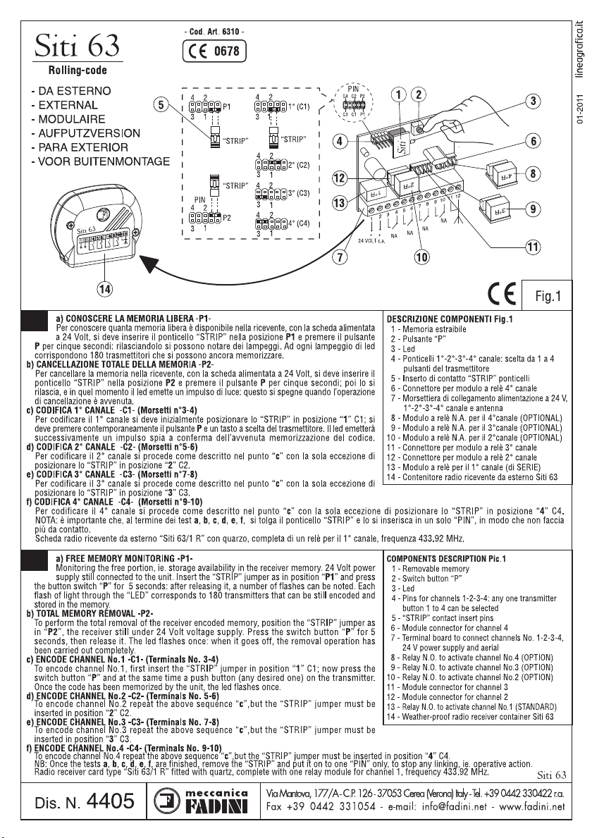
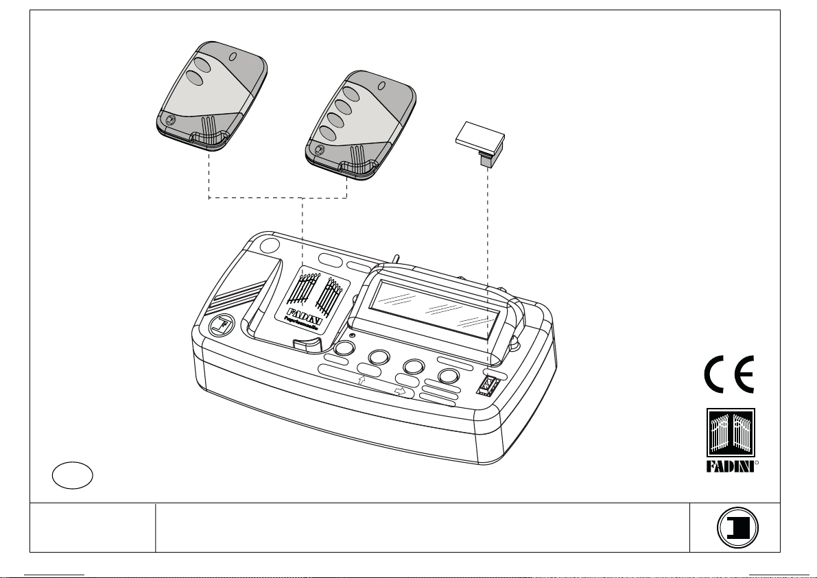
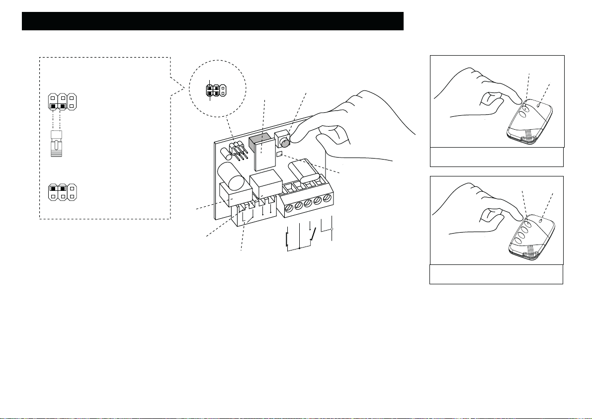
DESCRIPTION DES COMPOSANTS Fig.1
1 - Mémoire enfichable
2 - Poussoir “P”
3 - Pontage “STRIP”
4 - Ponts 1er et 2ème canal: choisir le poussoir
émetteur de 1 à 4 max.
5 - Led
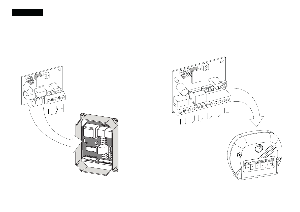
6 - Relais pour actionner le 2ème canal
7 - Borne de raccordement 2ème canal contact
N.F. et N.O. et antenne
8 - Connecteur enfichable femelle 1er canal et
alimentation 24 V
9 - Relais pour actionner le 1er canal
10 - Programmateur électronique série Elpro
11 - Connecteur enfichable mâle
F
BESCHREIBUNG DER BESTANDTEILEN Abb.1
1 - Abnehmbarer Speicher
2 - Schalter “P”
3 - “STRIP” Codierbrücke
4 - 1.-2. Kanal Anschlüsse: Wahl des
Sendersauslösers von 1 bis 4 max.
5 - Led
6 - Relais zur Aktivierung des 2. Kanals
7 - Klemme 2. Kanal N.C. und N.O. Anschluss
und Antenne (Klemmen 1-2)
8 - Einsteckverbinder Mutter des 1. Kanals und
24 V Speisung
9 - Relais zur Steuerung des 1. Kanals
10 - Elektronische Steuerung Serie Elpro
11 - Einsteckverbinder Zapfen
D
a) PARA CONOCER LA MEMORIA LIBRE -P1-
Para averiguar cuanta memoria está disponible en el radiorreceptor, siempre estando la ficha alimentada
a 24 Voltios, hay que conectar el puente “STRIP” en la posición “P1” y apretar el pulsador “P” durante 5
segundos: soltandolo se pueden observar unos relampagueos. Cada relampagueo de led señala que hay 180
transmisores que pueden memorizarse aun.
b) BORRADURA TOTAL DE LA MEMORIA -P2-
Se borra toda la memoria codificada en el receptor colocando el “STRIP” como un puente en la posición “P2”,
siempre estando alimentada la ficha misma a 24 Voltios. Se aprieta el pulsador “P” durante 5 segundos, se le
suelta y en aquel momento el led emite un impulso luminoso, que se apaga cuando la operación de borradura
se ha realizado.
c) CODIFICACION 1er CANAL -C1- (Conectador enchufable)
Para codificar el 1er canal, colocar ante todo el “STRIP” en la posición “1” C1; a continuación, apretar al mismo
tiempo durante 5 segundos el pulsador “P” y luego una tecla a elección del transmisor. El led emitirá después
una impulsión de luz para confirmar que el código ha sido memorizado.
d) CODIFICACION 2°CANAL -C2- (Borne 3-4-5)
Para codificar el 2°canal, actuar como reseñado en el apartado “c” excepto únicamente que se coloca el “STRIP”
en la posición “2” C2.
NOTA: es importante que al final de los ensayos a,b,c,d, se quiete el puente “STRIP” y se lo introduzca en un sólo “PIN”, de forma que el mismo no haga más contacto
Ficha enchufable radiorreceptor “Siti 63/2 R” con cuarzo, equipada de dos módulos relés para el 1er y el 2°canal, frequencia 433.92MHz
DESCRIPCION COMPONENTES Fig.1
1 - Memoria amovible
2 - Pulsador “P”
3 - Pieza de contacto “STRIP” puentes
4 - Puentes 1er y 2°canal: eleccion desde 2 hasta
4 pulsadores del transmisor
5 - Led
6 - Relé para activar el 2°canal
7 - Borne de conexion 2°canal contacto N.C.-N.A.
y antena (borne 1-2)
8 - Conectador enchufable hembra 1er canal y
suministro de corriente 24 V
9 - Relé para activar el 1er canal
10 - Programador electronico serie Elpro
11 - Conectador enchufable macho
E
BESCHRIJVING ONDERDELEN (FIG.1)
1 - Uitneembaar geheugen
2 - Drukknop “P”
3 - Inzetcontact “STRIP” geleiderbruggen
4 - Geleiderbruggen 1e -2e kanaal: keuze uit 1 tot
4 drukknoppen van de zenderr
5 - Led
6 - Relais om het 2e kanaal te activeren
7 -
Verbindingsklem 2e kanaal normaal geopend-,
normaal gesloten contact en antenne (1-2)
8 - Vrouwtjes-koppelingsconnector 1e kanaal en
stroomtoevoer van 24 Volt
9 - Relais om het 1e kanaal te activeren
10 - Elektronische programmeereenheid Elpro serie
11 - Mannetjes-koppelingsconnector

Siti 63
- ROLLING-CODE-
INTRODUCTION
AERIAL
+
24 VOLT a.c.
POWER SUPPLY
1st
CHANNEL
2n
CHANNEL
3r
CHANNEL
4th
CHANNEL
12345678910 11 12
AERIAL
External Radio
Receiver
Control Pannel External Radio
Receiver Case
page 3
Siti 63 Radio Receiver and Transmitter use a self-learning 433,9 Rolling-Code technology: ever y time a button is pressed and a signal is emitted, the
transmitter code is changed at random by the system. Total security is so guaranteed.
Besides having the traditional Radio Transmitter and Receiver encoding procedure, Siti 63 both Transmitters and Receivers can be customized by the
installer entering up to two "keys" (that is 16 numerical codes) by means of a Birio LC Device. This customizing operation is not functional but it
responds to the needs for an exclusive product. The use of Birio LC device allows to create new transmitters with no need to operate directly on the
installation.
Siti 63
Siti
Siti 63
- ROLLING-CODE-
1
2
3
4
5
1°R
2°R
Plug-in Radio
Receiver
Siti
R
pushbutton
transmitter
Removable
Memory
4 pushbutton
transmitter
Siti 63
ROLLING-CODE 433,92 MHz-
Birio LC Device
to key-encode radio receivers and
transmitters
SITI 63 INSTRUCTIONS
Drwg. No. 4395
GB
F
MEMORYENTER
KEY
DELETE
KEY
COPY
REPLACE
DELETE
COPY ONE BUTTON
SELECT
CODE
MEMORY
Birio LC
SUPPLY
9 VOLT
ON / OFF
GB
4213
ma e in Italy
Siti
Siti
Siti
the gate opener

Siti 63
BUTTON P
REMOVABLE
MEMORY
PIN
LED
POSSIBILE PIN COMBINATIONS
EXTERNAL Siti 63 RADIO RECEIVER ENCODING OPERATION
STRIP
JUMPER
1
3
1
3
1
3
1
3
24
24
24
24
1°R
2°R
+
24 VOLT a.c.
POWER SUPPLY
1st
CHANNEL
2n
CHANNEL
3r
CHANNEL
4th
CHANNEL
12345678910 11 12
AERIAL RELAY
RELAY
1st CHANNEL
RELAY
C4 C2 P2
C3 C1 P1
(C1)
Relay 1 -
1st channel
(C2)
Relay 2 -
2n channel
(C3)
Relay 3 -
3r channel
(C4)Relay 4 -
4th channel
3°R
4°R
PUSH
BUTTON LED
PUSH
BUTTON LED
pushbuttons Siti 63
4 pushbuttons Siti 63
page 4
1) Insert the removable Memory and supply the External Radio Receiver by connecting terminals 1(-) and (+) to 4 V a.c. carry out connections of the
N.O: contact to activate the required channel.
) Insert the "Strip" jumper into C1 position stimulating the 1R: relay corresponding to 3 and 4 terminals (1st Channel)
3) Press simultaneously P pushbutton on the Radio and any pushbutton on the transmitter you intend to operate as 1st Channel, for about 5 seconds. As
storing confirmation the red led will illuminate. Release the push button P and the push button on the transmitter.
4) Remove the "Strip" jumper and plug it into only one PIN.
5) For nd, 3rd and 4th channel storing, operate as above and plug the "Strip" jumper into the respective PINS (see picture) and the relays into the
respective connectors corresponding to the required channel.
SHOULD 24 a.c. 13 c.c. BE INTERRUPTED, THE CODE IS KEPT IN THE REMO ABLE MEMORY AND IT IS POSSILE TO INSERT IT INTO ANOTHER PC CARD.
page
CONTENTS
CONTENTS...............................................................................................................
INTRODUCTION........................................................................................................
EXTERNAL RADIO RECEIVER ENCODING OPERATION................................................
PLUG-IN RADIO RECEIVER ENCODING OPERATION..................................................
RADIO RECEIVER FREE MEMORY READING...............................................................
RADIO RECEIVER MEMORY DELETING.......................................................................
TRANSMITTER COPYING ON THE SAME RECEIVER......................................................
RADIO TRANSMITTER CODE DELETING.......................................................................
"BIRIO LC" DEVICE (KEY-READING)............................................................................
- "BIRIO LC" DEVICE...................................................................................................
- "BIRIO LC" DEVICE TYPES.........................................................................................
- "BIRIO LC" DEVICE OPERATING............................ ...................................................
- TRANSMITTER DATA READING..................................................................................
- TRANSMITTER KEY ENCODING.................................................................................
- TRANSMITTER KEY DELETING....................................................................................
- TRANSMITTER COPY.................................................................................................
- TRANSMITTER REPLACING.......................................................................................
- TRANSMITTER DELETING FROM THE RADIO RECEIVER..............................................
- COPY ONE BUTTON (COMMON BUTTON)...............................................................
- SET THE TRANSMITTER CODE...................................................................................
- MEMORY DATA READING.......................................................................................
- MEMORY KEY ENCODYING.....................................................................................
- MEMORY KEY DELETING..........................................................................................
- MEMORY COPYING................................................................................................
- DIFFERENT INSTALLATIONS LEARNING......................................................................
- RADIO RECEIVER'S MULTIPLE LEARNING..................................................................
"BIRIO TOOL" PC SOFTWARE INSTALLATION AND USE.................................................
- "BIRIO TOOL" OPENING...........................................................................................
- MEMORY DATA DOWNLOADING............................................................................
- TRANSMITTER DATA DOWNLOADING.......................................................................
- TRANSMITTER CODE SEARCH IN THE PC.................................................................
- TRANSMITTER COPYING..........................................................................................
- TRANSMITTER REPLACING.......................................................................................
- TRANSMITTER DELETING..........................................................................................
- COPY ONE BUTTON (COMMON BUTTON)...............................................................
- ADDING A TRANSMITTER TO THE MEMORY...............................................................
DATA PRINTING.........................................................................................................
BATTERY RECHARGE.................................................................................................
SPECIFICATIONS.......................................................................................................
DIMENSIONS.............................................................................................................
page
page 3
page 4
page 5
page 6
page 7
page 8
page 9
page 10
page 11
page 1
page 13
page 14
page 15
page 16
page 17
page 18
page 19
page 0
page 1
page
page 3
page 4
page 5
page 7
page 8
page 9
page 30
page 31
page 3
page 33
page 34
page 35
page 36
page 37
page 38
page 39
page 40
page 41
page 4
Siti
Siti 63

Siti 63
- ROLLING-CODE-
INTRODUCTION
AERIAL
+
24 VOLT a.c.
POWER SUPPLY
1st
CHANNEL
2n
CHANNEL
3r
CHANNEL
4th
CHANNEL
12345678910 11 12
AERIAL
External Radio
Receiver
Control Pannel External Radio
Receiver Case
page 3
Siti 63 Radio Receiver and Transmitter use a self-learning 433,9 Rolling-Code technology: ever y time a button is pressed and a signal is emitted, the
transmitter code is changed at random by the system. Total security is so guaranteed.
Besides having the traditional Radio Transmitter and Receiver encoding procedure, Siti 63 both Transmitters and Receivers can be customized by the
installer entering up to two "keys" (that is 16 numerical codes) by means of a Birio LC Device. This customizing operation is not functional but it
responds to the needs for an exclusive product. The use of Birio LC device allows to create new transmitters with no need to operate directly on the
installation.
Siti 63
Siti
Siti 63
- ROLLING-CODE-
1
2
3
4
5
1°R
2°R
Plug-in Radio
Receiver
Siti
R
pushbutton
transmitter
Removable
Memory
4 pushbutton
transmitter
Siti 63
ROLLING-CODE 433,92 MHz-
Birio LC Device
to key-encode radio receivers and
transmitters
SITI 63 INSTRUCTIONS
Drwg. No. 4395
GB
F
MEMORYENTER
KEY
DELETE
KEY
COPY
REPLACE
DELETE
COPY ONE BUTTON
SELECT
CODE
MEMORY
Birio LC
SUPPLY
9 VOLT
ON / OFF
GB
4213
ma e in Italy
Siti
Siti
Siti
the gate opener

Siti 63
BUTTON P
REMOVABLE
MEMORY
PIN
LED
POSSIBILE PIN COMBINATIONS
EXTERNAL Siti 63 RADIO RECEIVER ENCODING OPERATION
STRIP
JUMPER
1
3
1
3
1
3
1
3
24
24
24
24
1°R
2°R
+
24 VOLT a.c.
POWER SUPPLY
1st
CHANNEL
2n
CHANNEL
3r
CHANNEL
4th
CHANNEL
12345678910 11 12
AERIAL RELAY
RELAY
1st CHANNEL
RELAY
C4 C2 P2
C3 C1 P1
(C1)
Relay 1 -
1st channel
(C2)
Relay 2 -
2n channel
(C3)
Relay 3 -
3r channel
(C4)Relay 4 -
4th channel
3°R
4°R
PUSH
BUTTON LED
PUSH
BUTTON LED
pushbuttons Siti 63
4 pushbuttons Siti 63
page 4
1) Insert the removable Memory and supply the External Radio Receiver by connecting terminals 1(-) and (+) to 4 V a.c. carry out connections of the
N.O: contact to activate the required channel.
) Insert the "Strip" jumper into C1 position stimulating the 1R: relay corresponding to 3 and 4 terminals (1st Channel)
3) Press simultaneously P pushbutton on the Radio and any pushbutton on the transmitter you intend to operate as 1st Channel, for about 5 seconds. As
storing confirmation the red led will illuminate. Release the push button P and the push button on the transmitter.
4) Remove the "Strip" jumper and plug it into only one PIN.
5) For nd, 3rd and 4th channel storing, operate as above and plug the "Strip" jumper into the respective PINS (see picture) and the relays into the
respective connectors corresponding to the required channel.
SHOULD 24 a.c. 13 c.c. BE INTERRUPTED, THE CODE IS KEPT IN THE REMO ABLE MEMORY AND IT IS POSSILE TO INSERT IT INTO ANOTHER PC CARD.
page
CONTENTS
CONTENTS...............................................................................................................
INTRODUCTION........................................................................................................
EXTERNAL RADIO RECEIVER ENCODING OPERATION................................................
PLUG-IN RADIO RECEIVER ENCODING OPERATION..................................................
RADIO RECEIVER FREE MEMORY READING...............................................................
RADIO RECEIVER MEMORY DELETING.......................................................................
TRANSMITTER COPYING ON THE SAME RECEIVER......................................................
RADIO TRANSMITTER CODE DELETING.......................................................................
"BIRIO LC" DEVICE (KEY-READING)............................................................................
- "BIRIO LC" DEVICE...................................................................................................
- "BIRIO LC" DEVICE TYPES.........................................................................................
- "BIRIO LC" DEVICE OPERATING............................ ...................................................
- TRANSMITTER DATA READING..................................................................................
- TRANSMITTER KEY ENCODING.................................................................................
- TRANSMITTER KEY DELETING....................................................................................
- TRANSMITTER COPY.................................................................................................
- TRANSMITTER REPLACING.......................................................................................
- TRANSMITTER DELETING FROM THE RADIO RECEIVER..............................................
- COPY ONE BUTTON (COMMON BUTTON)...............................................................
- SET THE TRANSMITTER CODE...................................................................................
- MEMORY DATA READING.......................................................................................
- MEMORY KEY ENCODYING.....................................................................................
- MEMORY KEY DELETING..........................................................................................
- MEMORY COPYING................................................................................................
- DIFFERENT INSTALLATIONS LEARNING......................................................................
- RADIO RECEIVER'S MULTIPLE LEARNING..................................................................
"BIRIO TOOL" PC SOFTWARE INSTALLATION AND USE.................................................
- "BIRIO TOOL" OPENING...........................................................................................
- MEMORY DATA DOWNLOADING............................................................................
- TRANSMITTER DATA DOWNLOADING.......................................................................
- TRANSMITTER CODE SEARCH IN THE PC.................................................................
- TRANSMITTER COPYING..........................................................................................
- TRANSMITTER REPLACING.......................................................................................
- TRANSMITTER DELETING..........................................................................................
- COPY ONE BUTTON (COMMON BUTTON)...............................................................
- ADDING A TRANSMITTER TO THE MEMORY...............................................................
DATA PRINTING.........................................................................................................
BATTERY RECHARGE.................................................................................................
SPECIFICATIONS.......................................................................................................
DIMENSIONS.............................................................................................................
page
page 3
page 4
page 5
page 6
page 7
page 8
page 9
page 10
page 11
page 1
page 13
page 14
page 15
page 16
page 17
page 18
page 19
page 0
page 1
page
page 3
page 4
page 5
page 7
page 8
page 9
page 30
page 31
page 3
page 33
page 34
page 35
page 36
page 37
page 38
page 39
page 40
page 41
page 4
Siti
Siti 63

PIN
EXTERNAL Siti 63 RADIO RECEIVER ENCODING OPERATION
RELAY
1st CHANNEL
RELAY
2n CHANNEL
(C1)
Relay 1 -
1st channel
(C2)
Relay 2 -
2n channel
PUSH
BUTTON P
2n CHANNEL
N.O. OR N.C.
CONTACTS
TO FIT INTO CONTROL
PANNEL
LED
REMOVABLE
MEMORY
1°R
2°R
AERIAL
1
2
3
4
5
+
STRIP
JUMPER
POSSIBLE PIN COMBINATIONS
1
1
2
2
C2
P2
C1
P1
page 5
SHOULD 24 AC 13 CC BE INTERRUPTED, THE CODE IS KEPT IN THE REMO ABLE MEMORY AND IT IS POSSILE TO
INSERT IT INTO ANOTHER PC CARD.
1) Insert the removable Memory and supply the Plug-in Radio Receiver by plugging it into the control panel.
) Insert the "Strip" jumper into C1 position stimulating the 1R: this corresponds to 3 and 4 terminals (1st Channel)
3) Press simultaneously P pushbutton on the Radio and any pushbutton on the transmitter you intend to operate as 1st Channel, for about 5 seconds. As
storing confirmation the red led will illuminate. Release the push button P and the push button on the transmitter.
4) Remove the "Strip" jumper and plug it into only one PIN.
5) For 2nd channel storing, operate as above and plug the "Strip" jumper into C (stimulating the R relay); connect the 2nd channel (NO or NC) then push
the button on the transmitter.
PUSH
BUTTON LED
PUSH
BUTTON LED
pushbuttons Siti 63
4 pushbuttons Siti 63
1
3
24
(TOTAL MEMORY DELETION)
P2
P2
Siti 63 RADIO RECEIVER MEMORY DELETING
EXTERNAL RADIO RECEIVER
REMOVABLE
MEMORY
PIN
LED
1°R
2°R
+
24 VOLT AC
POWER SUPPLY
1st
CHANNEL
2n
CHANNEL
3r
CHANNEL
4th
CHANNEL
12345678910 11 12
AERIAL
STRIP
JUMPER
PIN
LED
REMOVABLE
MEMORY
1°R
2°R
AERIAL
1
2
3
4
5
+
1
2
STRIP
JUMPER
TO FIT INTO CONTROL PANEL
PLUG-IN RADIO RECEIVER
page 7
1) )Insert the removable Memory and supply the External Radio Receiver with 4 V a.c. by terminals 1(-) and (+) ; and plug the Radio Receiver into control
panel.
) Insert the "Strip" jumper into P2 position
3) Press P pushbutton on the Radio Receiver for about 5 seconds. Release the push button P and the red led will illuminate: memory deleted
4) Remove the "Strip" jumper and plug it into only one PIN
PUSH BUTTON P
PUSH BUTTON P
Siti
Siti
Siti
Siti 63
Siti 63

Siti 63 TRANSMITTER COPYING ON THE SAME RECEIVER
4th Operation
Siti 63
4 buttons
Siti 63
buttons
AERIAL
1
2
3
4
5
1°R
2°R
PLUG-IN RECEIVER
EXTERNAL RECEIVER
+
24 VOLT a.c.
POWER SUPPLY
1st
CHANNEL
2n
CHANNEL
3r
CHANNEL
4th
CHANNEL
12345678910 11 12
AERIAL
1st Operation
A
nd Operation
Operations to be carried out in 30 seconds max time
3rd Operation
page 8
TO COPY NEW TRANSMITTERS OPERATING ON THE SAME RADIO RECEIVER, YOU NEED TO HAVE AN ENCODED TRANSMITTER AND TO CARRY
OUT TWO OPERATIONS SEQUENCELY. THESE OPERATIONS MUST BE EFFECTED AT A MAX DISTANCE OF 10 METRES FROM THE RADIO
RECEIVER, DULY POWER SUPPLIED, AERIAL CONNECTED
1st Operation: Push the 1st button on the new Radio Transmitter A and release when the Led turns off
nd Operation: Push the 2nd button on the new Radio Transmitter A as long as the Led turns off plus seconds. Then release
the button.
3rd Operation: Push the1st button on the encoded Radio Transmitter B and release when the Led turns off
4th Operation: Push the 2nd button on the encoded Radio Transmitter B and release when the Led turns off
Repeat these operations for any new Transmitter required.
Push 1st button
and release
when the led
turns off
New New
New
Push 1st button
and release when
the led turns off
Push 1st button and
release when the led
turns off
Push 1st button and
release when the led
turns off
Push nd button and
release when the led
turns off plus seconds
Push ndt button and
release when the led
turns off plus seconds
Push nd button and
release when the led
turns off
Push nd button
and release when
the led turns off
4th Operation
1st Operation nd Operation
New
3rd Operation
B
IMPORTANT: Transmitter copying is possible even if keys are encoded (see chapter about Birio LC device) provided that they were encoded by the same
Birio LC encoding device.
B
A
AA B
B
EXTERNAL RADIO RECEIVER
1
2
3
4
(FREE MEMORY)
P1
LED
REMOVABLE
MEMORY
REMOVABLE
MEMORY
LED
1°R
1°R
2°R
2°R
+
24 VOLT a.c.
POWER SUPPLY
1st
CHANNEL
2n
CHANNEL
3r
CHANNEL
4th
CHANNEL
12345678910 11 12
AERIAL
STRIP
JUMPER
1
2
(FREE MEMORY)
P1
STRIP
JUMPER
PIN
PIN
AERIAL
1
2
3
4
5
+
TO FIT INTO
CONTROL PANEL
PLUG-IN RADIO RECEIVER
page 6
1)Insert the removable Memory and supply the External Radio Receiver with 4 V a.c. by terminals 1(-) and (+) ; plug the Radio Receiver into the control
panel.
) Insert the "Strip" jumper into P1 position -free memory reading-
3) Press P pushbutton on the Radio Receiver for about 5 seconds. Release the push button P and the red led will flash: every flash corresponds to 180
transmitters to store, for ex: 7 flashes mean 7x180=1 60 trasmitters still to store, (180 transmitters multipied by 10 flashes is 1.800 transmitters to store)
4) Remove the "Strip" jumper and plug it into only one PIN
PUSH BUTTON P
PUSH BUTTON P
Siti
Siti
Siti
Siti
Siti 63 RADIO TRANSMITTER MEMORY READING

PIN
EXTERNAL Siti 63 RADIO RECEIVER ENCODING OPERATION
RELAY
1st CHANNEL
RELAY
2n CHANNEL
(C1)
Relay 1 -
1st channel
(C2)
Relay 2 -
2n channel
PUSH
BUTTON P
2n CHANNEL
N.O. OR N.C.
CONTACTS
TO FIT INTO CONTROL
PANNEL
LED
REMOVABLE
MEMORY
1°R
2°R
AERIAL
1
2
3
4
5
+
STRIP
JUMPER
POSSIBLE PIN COMBINATIONS
1
1
2
2
C2
P2
C1
P1
page 5
SHOULD 24 AC 13 CC BE INTERRUPTED, THE CODE IS KEPT IN THE REMO ABLE MEMORY AND IT IS POSSILE TO
INSERT IT INTO ANOTHER PC CARD.
1) Insert the removable Memory and supply the Plug-in Radio Receiver by plugging it into the control panel.
) Insert the "Strip" jumper into C1 position stimulating the 1R: this corresponds to 3 and 4 terminals (1st Channel)
3) Press simultaneously P pushbutton on the Radio and any pushbutton on the transmitter you intend to operate as 1st Channel, for about 5 seconds. As
storing confirmation the red led will illuminate. Release the push button P and the push button on the transmitter.
4) Remove the "Strip" jumper and plug it into only one PIN.
5) For 2nd channel storing, operate as above and plug the "Strip" jumper into C (stimulating the R relay); connect the 2nd channel (NO or NC) then push
the button on the transmitter.
PUSH
BUTTON LED
PUSH
BUTTON LED
pushbuttons Siti 63
4 pushbuttons Siti 63
1
3
24
(TOTAL MEMORY DELETION)
P2
P2
Siti 63 RADIO RECEIVER MEMORY DELETING
EXTERNAL RADIO RECEIVER
REMOVABLE
MEMORY
PIN
LED
1°R
2°R
+
24 VOLT AC
POWER SUPPLY
1st
CHANNEL
2n
CHANNEL
3r
CHANNEL
4th
CHANNEL
12345678910 11 12
AERIAL
STRIP
JUMPER
PIN
LED
REMOVABLE
MEMORY
1°R
2°R
AERIAL
1
2
3
4
5
+
1
2
STRIP
JUMPER
TO FIT INTO CONTROL PANEL
PLUG-IN RADIO RECEIVER
page 7
1) )Insert the removable Memory and supply the External Radio Receiver with 4 V a.c. by terminals 1(-) and (+) ; and plug the Radio Receiver into control
panel.
) Insert the "Strip" jumper into P2 position
3) Press P pushbutton on the Radio Receiver for about 5 seconds. Release the push button P and the red led will illuminate: memory deleted
4) Remove the "Strip" jumper and plug it into only one PIN
PUSH BUTTON P
PUSH BUTTON P
Siti
Siti
Siti
Siti 63
Siti 63

Siti 63 TRANSMITTER COPYING ON THE SAME RECEIVER
4th Operation
Siti 63
4 buttons
Siti 63
buttons
AERIAL
1
2
3
4
5
1°R
2°R
PLUG-IN RECEIVER
EXTERNAL RECEIVER
+
24 VOLT a.c.
POWER SUPPLY
1st
CHANNEL
2n
CHANNEL
3r
CHANNEL
4th
CHANNEL
12345678910 11 12
AERIAL
1st Operation
A
nd Operation
Operations to be carried out in 30 seconds max time
3rd Operation
page 8
TO COPY NEW TRANSMITTERS OPERATING ON THE SAME RADIO RECEIVER, YOU NEED TO HAVE AN ENCODED TRANSMITTER AND TO CARRY
OUT TWO OPERATIONS SEQUENCELY. THESE OPERATIONS MUST BE EFFECTED AT A MAX DISTANCE OF 10 METRES FROM THE RADIO
RECEIVER, DULY POWER SUPPLIED, AERIAL CONNECTED
1st Operation: Push the 1st button on the new Radio Transmitter A and release when the Led turns off
nd Operation: Push the 2nd button on the new Radio Transmitter A as long as the Led turns off plus seconds. Then release
the button.
3rd Operation: Push the1st button on the encoded Radio Transmitter B and release when the Led turns off
4th Operation: Push the 2nd button on the encoded Radio Transmitter B and release when the Led turns off
Repeat these operations for any new Transmitter required.
Push 1st button
and release
when the led
turns off
New New
New
Push 1st button
and release when
the led turns off
Push 1st button and
release when the led
turns off
Push 1st button and
release when the led
turns off
Push nd button and
release when the led
turns off plus seconds
Push ndt button and
release when the led
turns off plus seconds
Push nd button and
release when the led
turns off
Push nd button
and release when
the led turns off
4th Operation
1st Operation nd Operation
New
3rd Operation
B
IMPORTANT: Transmitter copying is possible even if keys are encoded (see chapter about Birio LC device) provided that they were encoded by the same
Birio LC encoding device.
B
A
AA B
B
EXTERNAL RADIO RECEIVER
1
2
3
4
(FREE MEMORY)
P1
LED
REMOVABLE
MEMORY
REMOVABLE
MEMORY
LED
1°R
1°R
2°R
2°R
+
24 VOLT a.c.
POWER SUPPLY
1st
CHANNEL
2n
CHANNEL
3r
CHANNEL
4th
CHANNEL
12345678910 11 12
AERIAL
STRIP
JUMPER
1
2
(FREE MEMORY)
P1
STRIP
JUMPER
PIN
PIN
AERIAL
1
2
3
4
5
+
TO FIT INTO
CONTROL PANEL
PLUG-IN RADIO RECEIVER
page 6
1)Insert the removable Memory and supply the External Radio Receiver with 4 V a.c. by terminals 1(-) and (+) ; plug the Radio Receiver into the control
panel.
) Insert the "Strip" jumper into P1 position -free memory reading-
3) Press P pushbutton on the Radio Receiver for about 5 seconds. Release the push button P and the red led will flash: every flash corresponds to 180
transmitters to store, for ex: 7 flashes mean 7x180=1 60 trasmitters still to store, (180 transmitters multipied by 10 flashes is 1.800 transmitters to store)
4) Remove the "Strip" jumper and plug it into only one PIN
PUSH BUTTON P
PUSH BUTTON P
Siti
Siti
Siti
Siti
Siti 63 RADIO TRANSMITTER MEMORY READING

Siti 63 RADIO TRANSMITTER CODE DELETING
page 9
Insert the removable "Strip" jumper on P1 position on the Radio Receiver:
1st Operation: Push the 2nd button on the Radio Transmitter and release when the Led
turns off
nd Operation: Push the 1st button on the new Radio Transmitter and release when the
Led turns off
Repeat these Operations for 6 times and end the sequence pushing the 1st button.
Then Insert the "Strip" jumper in only one PIN.
Repeat these operations for every transmitter you wish to delete.
N.B: IF THE NUMBER OF OPERATIONS OR THE TIME BEFORE NEXT PRESSING ARE MISTAKEN,
YOU MUST REPEAT THE OPERATIONS FROM THE BEGINNING, AND WAIT 1 MINUTE BEFORE
STARTING AGAIN.
IF YOU NEED TO DELETE A TRANSMITTER CODE OPERATE AT A MAX DISTANCE OF 10 METRES
FROM THE RADIO RECEIVER, DULY POWER SUPPLIED, AERIAL CONNECTED
IMPORTANT: Transmitter deleting is possible even if keys are encoded (see chapter about Birio LC device) provided that they were encoded by the same Birio
LC encoding device.
Siti 63
4 buttons
Siti 63
buttons
2n Operation 3r Operation 4th Operation 5th Operation 6th Operation
1st Operation
Push 1st button and release
when the led turns off
Push 1st button and release
when the led turns off
Push 1st button and release
when the led turns off
Push 1st button and release
when the led turns off
Push 1st button and release
when the led turns off
Push ndt button and release
when the led turns off
Push nd button and release
when the led turns off
Push nd button and release
when the led turns off
Push nd button and release
when the led turns off
Push nd button and release
when the led turns off
Push 1st button and release
when the led turns off
Push nd button and release
when the led turns off
nd Operation 3r Operation 4th Operation 5th Operation 6th Operation
1st Operation
Siti
PLUG-IN RADIO RECEIVER
P1
PIN
REMOVABLE
MEMORY
1°R
2°R
1
2
STRIP
JUMPER
LED
Relay
Relay
Relay
EXTERNAL RADIO RECEIVER
1
3
24
P1
REMOVABLE
MEMORY
PIN
LED
STRIP
JUMPER
page11
Drwg.4091
On/off switch
9 volt 300mA battery recharge connector
Serial cable Personal Computer connector
Memory or transmitter key entering and code
shifting
Transmitter and memory key deletion and
code entering
Copy, replace, delete, copy 1 button of the
transmitter and the memory
POWER SUPPLY: Birio LC device has an internal rechargeable battery, 6 hours autonomy , you can also operate it by 30V 50Hz power supply using a
9V 300mA adaptor. Maximum recharging time is 5 hours.
Power supply led
Button for encoding operations
and memory
Display
Birio LC
SUPPLY
9 VOLT ON / OFF
GB
MEMORY
REPLACE
DELETE
COPY ONE BUTTON
COPY
MEMORY ENTER KEY DELETE KEY
To fit removable memory
4213
SELECT
CODE
Siti
Siti
Siti
Siti
Siti
Siti
Siti
Siti
Siti
Siti
Siti
Siti
Siti

There are various kinds of Birio LC encoding devices belonging to different groups or families: Family A, Family B etc. distinguishable by an inner stamp),
each one independent from the other.
Every group is made up of two distinct Birio LC devices, each one having its own function (see picture referring to group A):
1) Master Device (Red)= enters only the 1st key and effects all operations on 1st key-encoded blank transmitters. It can also delete the nd key from slave
devices belonging to its family.
) Slave Device (Blue)= enters only the nd key if the 1st one was encoded by the Master or Master/Slave belonging to the same family, and operates on
nd key encoded radio transmitters.
Once the Slave Device (for example an installer's) has encoded the nd key, the Master Device will not be able to carry out any operation on those
transmitters or memories, but only the transmitter that stored the latest key will, in this case the Slave Device.
Please note that if you want to clear key-customized radio transmitters, you will have to delete the keys, by starting from the latest device that inserted the
nd key, and then the device that inserted the 1st.- repeat backwards the sequence stages in pictures -
NOTE: Key encoding can be effected by Birio LC Devices either before or after transmitter storing into the receiver.
BIRIO LC DEVICE TYPES
FAMILY
A = MASTER
(RESELLER)
A
A1= SLAVE
(INSTALLER)
page 1
BLANK 1st KEY
2n KEY
1st KEY-CODE
1st KEY
2n KEY
A1= SLAVE
(INSTALLER)
A = MASTER
(RESELLER)
1st KEY BLANK
A = MASTER
(RESELLER)
MEMORIA INSERISCI
CHIAVI
TOGLI
CHIAVI
DUPLICA
SOSTITUISCI
CANCELLA
COPIA UN TASTO
SELEZIONA
CODICE
MEMORIA
Birio LC
SUPPLY
9 VOLT
ON / OFF
I
MEMORIA INSERISCI
CHIAVI
TOGLI
CHIAVI
DUPLICA
SOSTITUISCI
CANCELLA
COPIA UN TASTO
SELEZIONA
CODICE
MEMORIA
Birio LC
SUPPLY
9 VOLT
ON / OFF
I
MEMORIA INSERISCI
CHIAVI
TOGLI
CHIAVI
DUPLICA
SOSTITUISCI
CANCELLA
COPIA UN TASTO
SELEZIONA
CODICE
MEMORIA
Birio LC
SUPPLY
9 VOLT
ON / OFF
I
MEMORIA INSERISCI
CHIAVI
TOGLI
CHIAVI
DUPLICA
SOSTITUISCI
CANCELLA
COPIA UN TASTO
SELEZIONA
CODICE
MEMORIA
Birio LC
SUPPLY
9 VOLT
ON / OFF
I
MEMORIA INSERISCI
CHIAVI
TOGLI
CHIAVI
DUPLICA
SOSTITUISCI
CANCELLA
COPIA UN TASTO
SELEZIONA
CODICE
MEMORIA
Birio LC
SUPPLY
9 VOLT
ON / OFF
I
MEMORIA INSERISCI
CHIAVI
TOGLI
CHIAVI
DUPLICA
SOSTITUISCI
CANCELLA
COPIA UN TASTO
SELEZIONA
CODICE
MEMORIA
Birio LC
SUPPLY
9 VOLT
ON / OFF
GB
MEMORIA INSERISCI
CHIAVI
TOGLI
CHIAVI
DUPLICA
SOSTITUISCI
CANCELLA
COPIA UN TASTO
SELEZIONA
CODICE
MEMORIA
Birio LC
SUPPLY
9 VOLT
ON / OFF
BIRIO LC DEVICE FOR KEY ENCODING
buttons
transmitter
buttons
transmitter
4 buttons
transmitter
4 buttons
transmitter
Receiver plug-in
Memory
Receiver plug-in
Memory
Personal
Computer
Software on
floppy disk
Birio LC encoding device to
insert customizing keys
Birio LC encoding device to
insert customizing keys
1st option ENCODING DEVICE ONLY IS USED 2nd option Dr g. 4091 - ENCODING DEVICE WITH PC SOFTWARE USE
page 10
The Siti 63 is a self-learning 433,9 Mhz frequency Radio Transmitter that can fit any gate automation installation with traditional enconding procedures. For
a more professional use any Siti 63 transmitter can be key-customized by the installer and the reseller using the Birio LC Device for key-encoding. This
operation allows market and customers' protection. A software for PC is supplied with the Birio LC Device as a tool to manage the key-customized
installations.
NOTE: Keys can only be encoded by the Birio Devices, either before or after transmitter storing on the receiver provided that the key encodying
operation is carried out on both the transmitter and on the memory.
IMPORTANT:ONLY THE BIRIO LC DEVICE WHICH ENCODED THE KEY CAN CARRY OUT ALL STORING, COPYING AND DELETING OPERATIONS
4213
4213
Siti
Siti
Siti
Siti
Siti
Siti
Siti
Siti
Siti
Siti
Siti
Siti
Siti
Siti
Siti
Siti
Siti
Siti
GB

page 13
BIRIO LC DEVICE OPERATING
The Birio LC device has a practical and intuitive use, it does not allow the codification between the Radio Receiver and the Transmitter, but it can copy,
replace and delete both clear and key-encoded transmitters (provided that the keys were encoded by the same Birio Lc Device); and copy either blank
or key-encoded Memories(provided that the keys were encoded by the same Birio Lc Device).
Leds lighting on the Device will help during the operations. Every operation is carried out simply by pushing the corresponding button on the Device.
To return from mode Transmitter to mode Memory and viceversa simply turn off and turn on the Device. Remember that when the Device is turned
off all received information is cancelled. Therefore after turning the Device on and starting with the new operations it is necessary to send the
information to the Birio LC Device of the transmitter and the memory you need to operate in.
TRANSMITTER:
As soon as the Birio LC Device is switched on, it is in mode Transmitter; if the corresponding buttons are pushed all information about the key-codes and
the family of the Device will be displayed.
A Birio LC Device can read the data of a transmitter which was key-encoded by a Birio LC Device belonging to a different family. In this case the presence
of the key and and the type of Device that encoded the transmitter are displayed. If the message Error is displayed it means that the Birio LC Device did
not read the transmitter information and thus no operation can be carried out.
MEMORY: After switching on the Birio LC Device, push the Memory button (the first button on the left) and you enter Memory mode: all information about
the key-codes and the family of the Device will be displayed.
A Birio LC encoding Device can read the data of a Memory which was key-encoded by a Birio LC Device belonging to a different family. In this case the
presence of the key and and the type of Device that encoded the Memory are displayed.
If the message Error is displayed it means that the Birio LC Device did not read the Memory information and thus no operation can be carried out.
"BIRIO TOOL" PC SOFTWARE: The Birio LC Device can also be used as a support to the PC software for customers' managing. Connect the Birio LC Device
to the PC serial port COM1, then open the software and turn on the Birio LC Device, click on connection and all the information (except the keys) of the
Memory and the Transmitter will be displayed.
Key-encoding must be carried out according to the family of the Birio LC Device.
- The Master Device (for ex. A) encodes clear Transmitters and Memories with the 1st key C1
- The Slave Device (for ex. A1, A ,...) encodes only the nd key (C ) into those Transmitters and Memories which were 1st-key encoded by the Master
Device belonging to the same family
If an "Error" message is displayed it means that the operation was not correctly carried out, or that the transmitter was key-encoded by
a Birio device belonging to a different family.
2° Push the button Enter Key: "T- Enter Key" will be displayed, followed
by "Enter Transmitter"
IMPORTANT: when the operation is completed, check the transmitter information by following the operation "transmitter data reading"
on page 14. page 15
1° Follow the operation Transmitter data
reading page 14
3°
Position the transmitter onto the Birio LC Device . When the led turns off the
operation is completed.
N.W. If, when the led turns off, another transmitter is positioned, before
TRANSMITTER is displayed, it is possible to encode this second transmitter too.
MEMORIY ENTER
KEYS
DELETE
KEYS
COPY
REPLACE
DELETE
COPY ONE BUTTON
SELECT
CODE
MEMORY
Birio LC
GB
No Key
Transmitter co e:
00 20 D9
DISPLAY
Enter transmitter
T - Enter Key
DISPLAY
TRANSMITTER KEY ENCODING
4213
TRANSMITTER
DISPLAY
TRANSMITTER
DISPLAY
REPLACE
DELETE
COPY ONE BUTTON
COPY
MEMORY ENTER
KEYS
DELETE
KEYS
SELECT
CODE
Siti
Siti

Key deleting operation can be carried out according to the Device family:
- The Master Device (for ex. A) can delete the 1st and the nd key to Transmitters and Memories which were encoded with keys beloging to the same
family
- The Slave Device (for ex. A1, A ,...) can delete only the nd key (C ) from those Transmitters and Memories which were encoded with the 1st and the
nd key.
If an "Error" message is displayed it means that the operation was not correctly carried out, or that the transmitter is encoded with
a key-code belonging to a different family.
IMPORTANT: when the operation is completed, check the transmitter information by following the operation
"transmitter data reading" on page 14.
page 16
1° Follow the operation transmitter data reading, page 14.
Push the button Delete Key: the message "T- Delete Key" followed by "Enter
Transmitter" will be displayed
2°
3°
Position the transmitter onto the Birio LC Device . When the led turns off the
operation is completed.
N.W. If, when the led turns off, another transmitter is positioned, before
TRANSMITTER is displayed, it is possible to delete the key to this second
transmitter too.
TRANSMITTER KEY DELETING
With this operation the Birio LC Device will read, recognize and display the Transmitter key-codes and the family they belong to.
If an "Error" message is displayed it means that the operation was not correctly carried out, or that the transmitter is encoded
with a key-code belonging to a different family.
1° Switch on the Birio LC Device and the led will
illuminate. TRANSMITTER mode is immediately
displayed.
2°
Push any transmitter button and one of the following information will be
displayed:
- No Key;
- 1 Key : Family...
- Keys: Family...
and then the transmitter code will be displayed
Return to mode transmitter.
All the following operations will refer to this transmitter whose information was read the last by the Birio LC
Device.
IMPORTANT: If during the 1st and the nd phase of this operation the button "Copy-Substitute-Delete-Copy 1 button" is pressed, the message "PRESS
TRANSMITTER FIRST" will be displayed
3°
page 14
ON
OFF
SUPPLY
9 VOLT ON | OFF
MEMORY ENTER
KEYS
DELETE
KEYS
COPY
REPLACE
DELETE
COPY ONE BUTTON
SELECTIONNER
CODE
Birio LC
SUPPLY
9 VOLT
ON / OFF
No Key
DISPLAY
Transmitter Co e:
00 20 D9
TRANSMITTER DATA READING
TRANSMITTER
DISPLAY
Enter Transmitter
T - Delete Key
DISPLAY
TRANSMITTER
DISPLAY
TRANSMITTER
DISPLAY
TRANSMITTER
DISPLAY
REPLACE
DELETE
COPY ONE BUTTON
COPY
MEMORY ENTER
KEYS
DELETE
KEYS
SELECT
CODE
MEMORIY ENTER
KEYS
DELETE
KEYS
COPY
REPLACE
DELETE
COPY ONE BUTTON
SELECT
CODE
MEMORY
Birio LC
GB
4213
Siti
Siti
Table of contents
Other fadini Transmitter manuals